Lots of loom developments this year! Soon after the first set of adjustable spindle units was finished I became aware that an unusually narrow chain wire spacing is being used by at least one paper maker. The chain wires that I saw were only 15-16 mm or 5/8″ apart. This was something my loom couldn’t do! This got me wondering if it would be possible to make these using smaller spindles. While making a new set of parts I discovered a few new things. Updates here.
The smaller spindles worked fine using the same drive weights and the same three wraps of the drive weight cords. The small ones are 1/2″ diameter, the larger, original ones 5/8″.
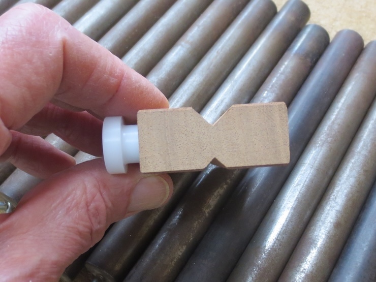
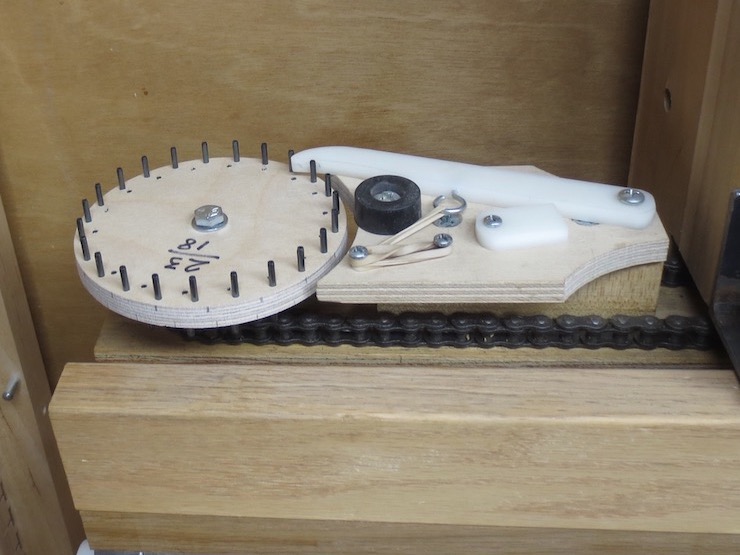
Here is a new spindle unit, one of almost four dozen made to complete a set. It is very similar to the ones described in post #63 but 1/8″ narrower. Using a metal dowel pin to hold the spindle up makes it easy to ream the spindle hole. Leaving the little curved notch at the front edge empty turns out to be a good idea.
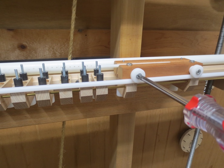
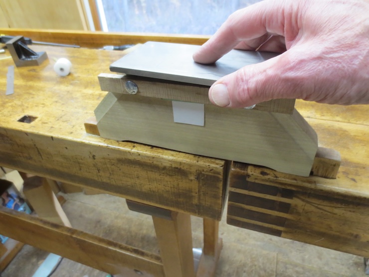
This is shown here. Instead of tacking short segments of rod to the individual units a length of 1/4″ diameter acetal rod is put in after the spindle units are fastened on. This is easier and adds one more bit of bracing to keep the spindle units lined up.
The rod extends the full width of the loom and sits neatly in the notches. It is clamped in place by tightening these screws.
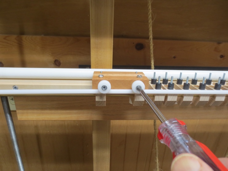
The other end is clamped to the block that catches the shuttle after the laid wire has been run through.
This is the older, thicker ‘prototype’ spindle unit showing how a short segment of the rod was tacked to the front.
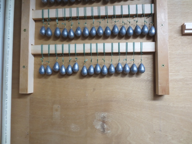
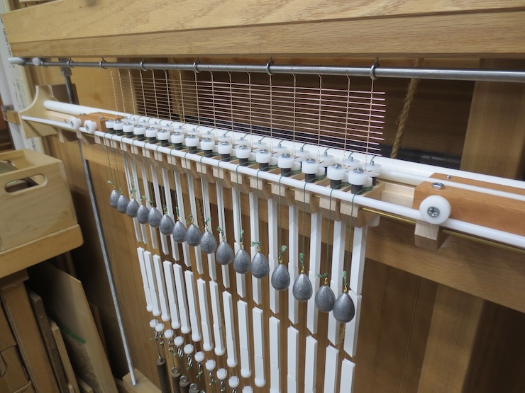
The weights that drive the spindles are now stored like this with their cords wound onto rectangular sticks. The sticks slide into notched bars fastened to the wall. Storing the weights and cords had always been a problem and this works really well.
The stick is unwound…
…and clamped to the bench where weights can be easily be removed one at a time.
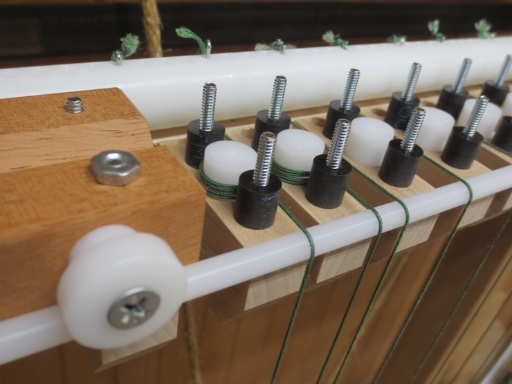
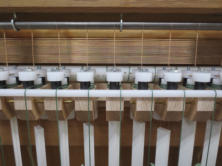
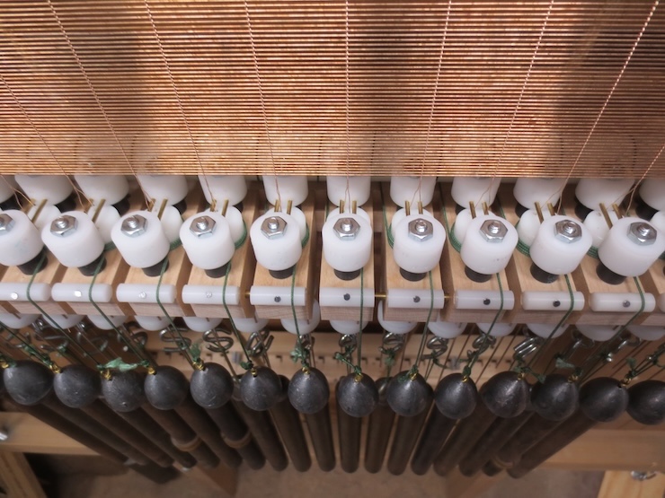
Now that the drive weights are added you can see another advantage of the continuous rod. The cords have no chance of slipping off into the gaps between the spindle units. The rod has two purposes. It provides a slippery surface for the cords to slide across and it elevates the cords in front so the cords stay separated as they wrap around the spindles and don’t overlap.
The metal rods in the new wire supports are stainless steel dowel pins, 1/16″ diameter by 7/8″ long.
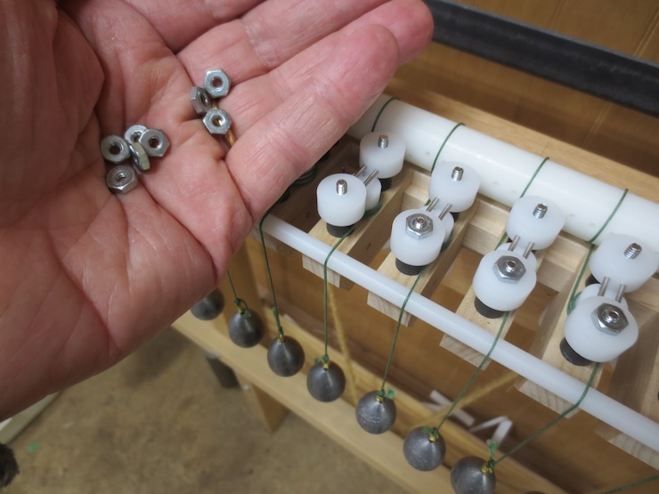
Nuts are needed only on the front studs. Finger tight is good.
These smaller wire slides are just under 5/8″ diameter to allow the narrower wire spacing to be made.
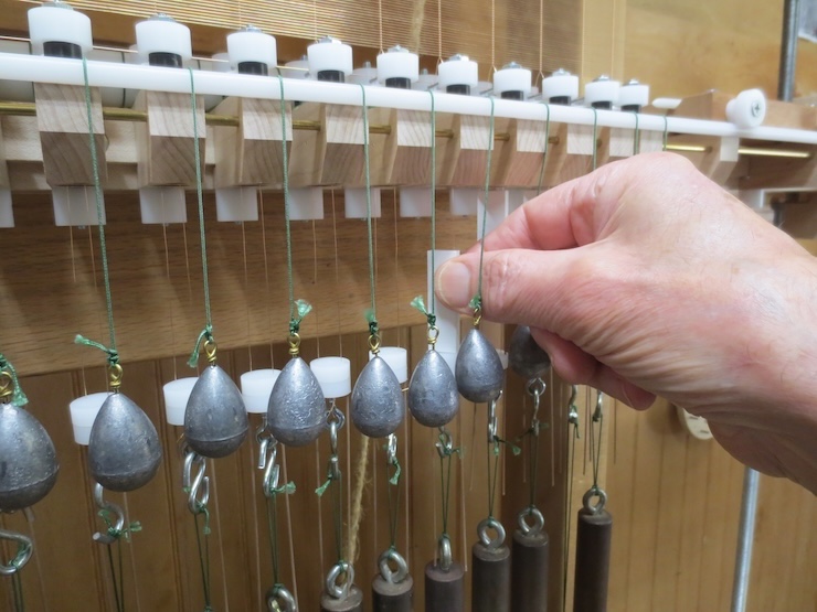
It turns out that 3/4″ diameter wire weights can be used to make 5/8″ chain spacing. All you have to do is hang half of the weights lower than the other half by using longer loops of cord. (Every other weight).
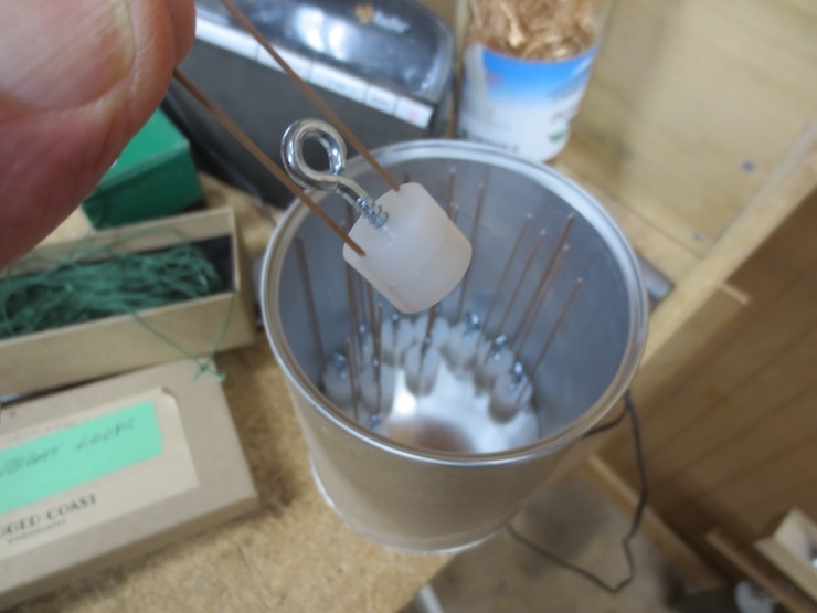
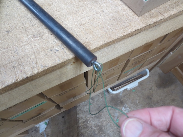
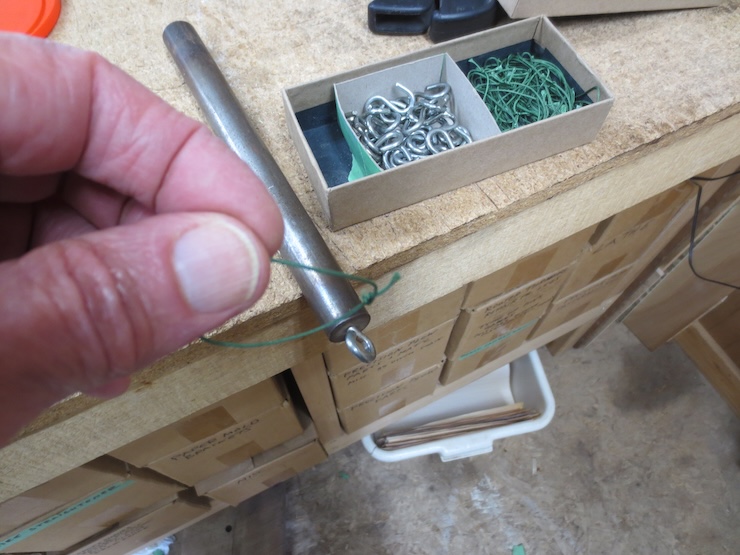
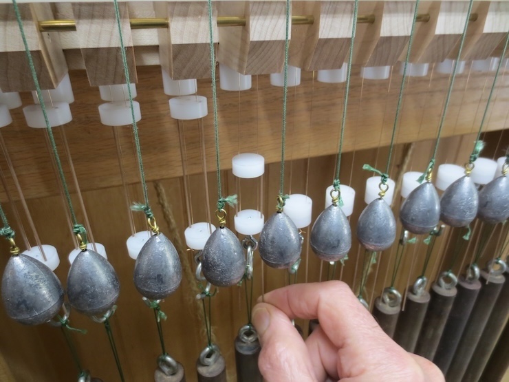
Needing two sizes of loops led to a more convenient way to store the wire weights; disassembled. To use, a weight is taken from its storage box, laid flat…
…and a prepared loop is cinched through the eye bolt.
Then an ‘S’ hook is added to connect the weight to the wire slide. No more tangled hooks and loops.
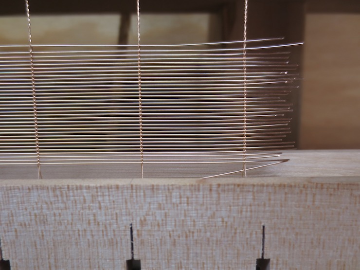
Only two of these longer loops are seen here because all of the middle spaces are wide; only the two end spaces are narrow.
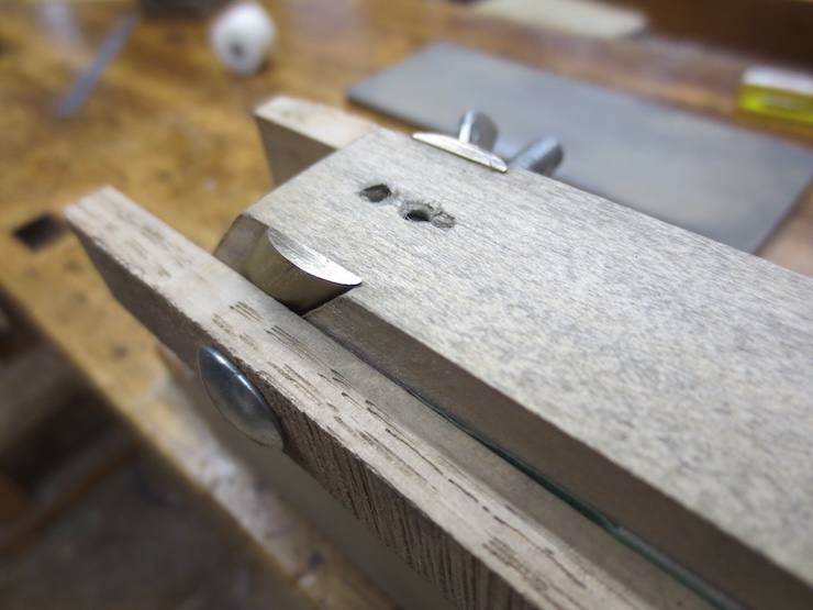
A laid wire will be inserted into the shallow tapered hole seen at the near (blurry) end of the shuttle. The shuttle guides the wire as it is pushed through (by that same laid wire).
After the wire is deposited onto the support rods the shuttle ends up resting in the groove. It is picked up and moved back to its starting place prior to inserting the next laid wire.
A single row of shorter foam board spacers at the bottom makes the last adjustments easier.
When removed, the shorter spacers leave a smaller space for the movable parts of the wire slides to fill. These can be pushed up to take up all the remaining space so the wires don’t twist up on themselves.
This is the first laid facing made with this new system of smaller parts that enable the loom to make the very narrow configuration (if needed). The next step is to test the newly outfitted loom by making a variety of sizes and types of mould.
Backing
The wire supports are flipped over to make a laid backing.
The ones in the back have been turned over to the higher position to give the wire twists a more relaxed angle for making widely spaced backing wires.
In post #63 I shimmed the shuttle rests up for backing wire. Now there are grooves of two different depths and the rests can simply be flipped over when changing from facing to backing.
This backing used the heaviest chain wire in my stock. It is .015″ in diameter annealed phosphor bronze. The heavier wires have a stronger tendency to twist around each other so it was a little trickier to keep the wire spacers in place. It’s delicate work to avoid bumping and dislodging the spacers while adjusting them. This is one place where the smaller parts seemed to have a (slight) negative effect. I more often use .013″ wire for this purpose which should work more easily.
Now I’ll try making all of my facings and backings using the smaller parts of this new system. If it proves to work well it could replace the older one.
A little more about the Spindle Units
The bottom of each spindle is supported by a 1/16″ diameter stainless steel dowel pin.
These are easy to remove which makes it a cinch to ream the spindle holes. It is usually necessary to re-true the holes so the spindles don’t bind. This is because wood changes seasonally. After a year or two this won’t be needed.
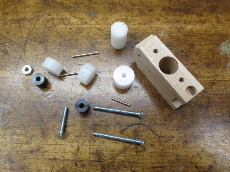
A disassembled spindle unit. Like the older spindle racks these are a challenge to make. But now only one set of these is needed to make any chain/rib spacing. And the minimum chain wire spacing has been reduced to 5/8″.
One more thing.
I’m not sure that this topic has been covered before. After the weighted cords are added the reel needs to be wound in a bit. To do this the reel crank is re-set. The crank is disengaged from the square shank formed on the end. After the reel and weights are re-positioned the crank is bolted back on to hold it there.
I’ve been working with and gradually improving my mould maker’s looms for about forty years. I have tried a few times to figure out how to do this but didn’t get very far until now.
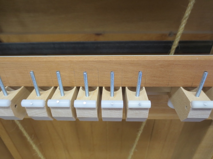
This is one of a number of spindle units that make it possible to create any spacing between chain wires. One of these is required for each pair of chain wires. The minimum (3/4″) is limited by the width of these wooden parts. But this doesn’t matter because it’s still a little closer than is possible with the weights and wire slides that this loom uses.
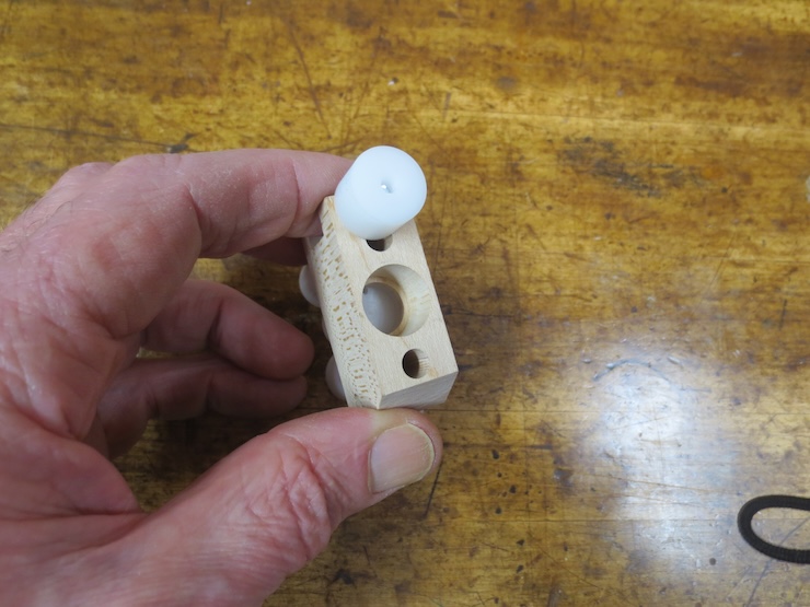
A view from the bottom. The white cylinder is screwed tight to lock the spindle unit in place.
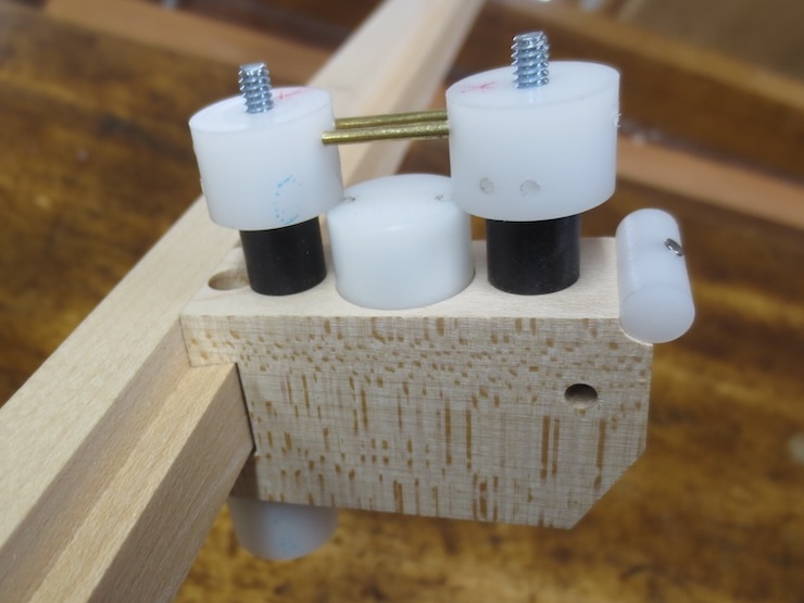
The units clamp to a wooden rail which is screwed to the traveling beam of the loom. A wooden wire trough (as with the previous spindle racks) is no longer needed. Instead a pair of 1/16″ brass rods held in place by plastic cylinders bridge the gap over each spindle to support laid wires as they are added. The wire supports can be placed in two positions, high or low. Here the pair of brass rods are high above the spindle to shape the more gradual twists of the widely spaced backing wires.
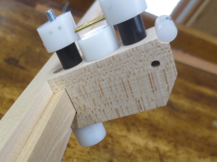
When making laid facings the support can be flipped over to put the rods in the lower position as shown here. This widens the wire angle to make tighter twists. The extra holes seen in both of these photos are the result of the experiments done to get the spacing right between the rods.
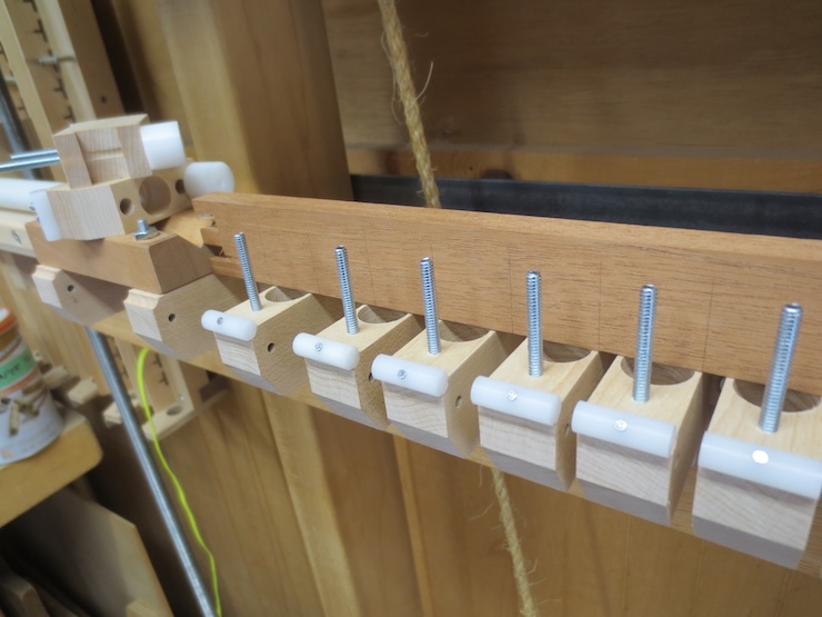
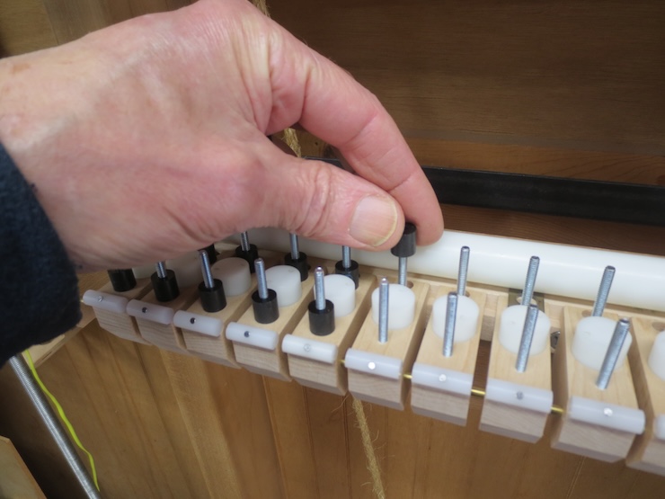
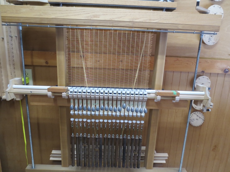
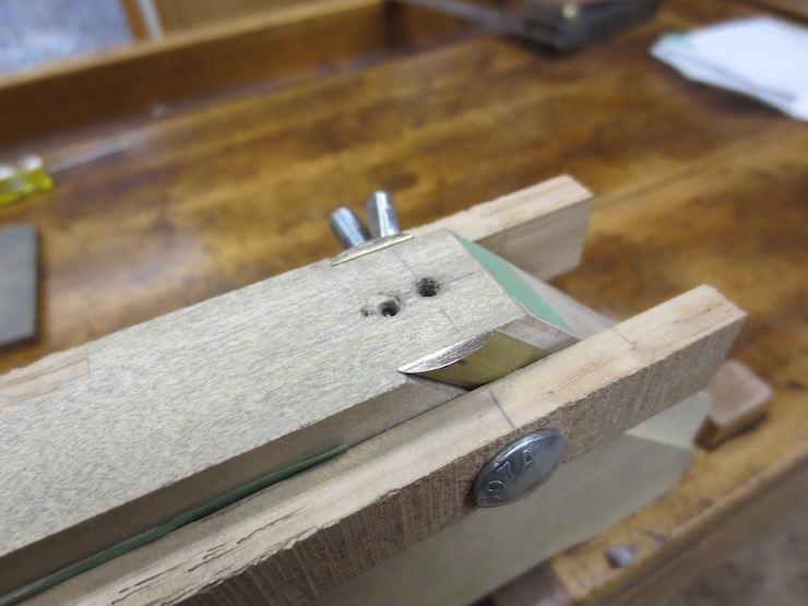
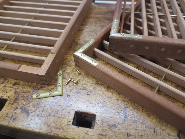
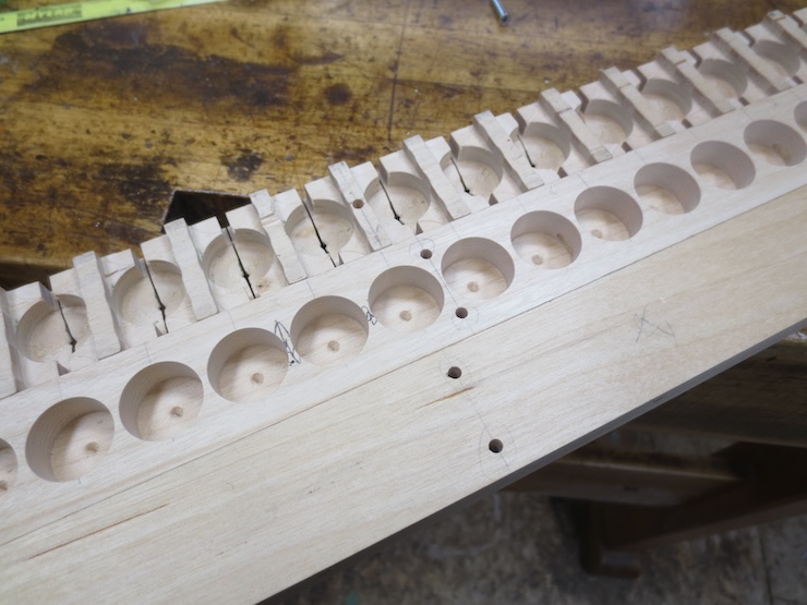
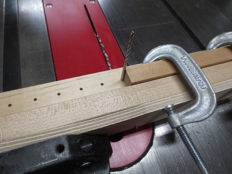
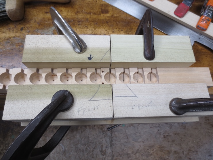
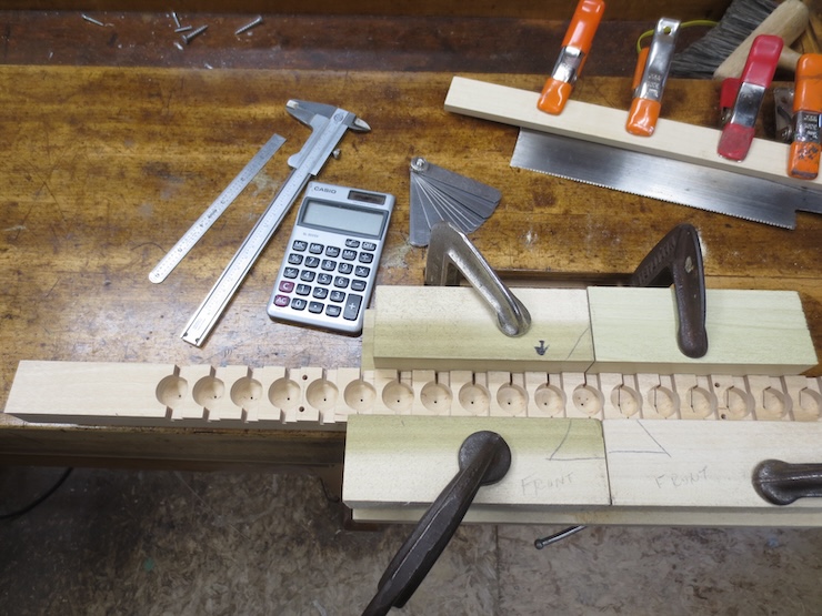
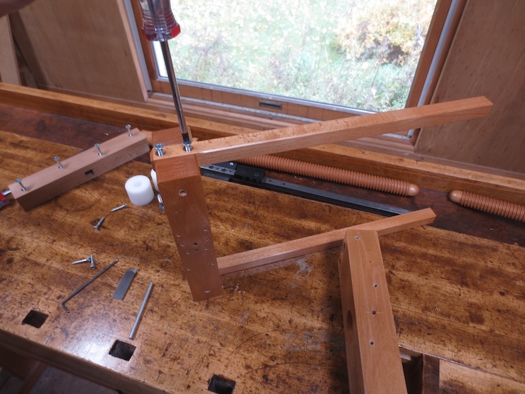
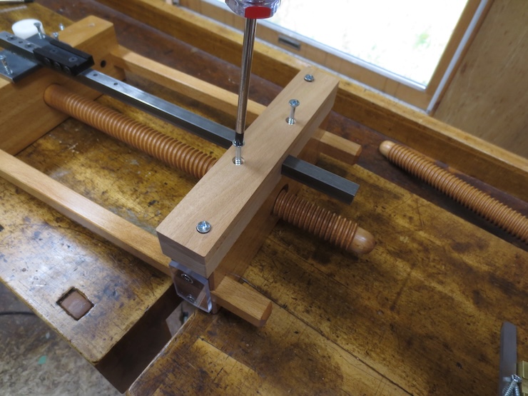
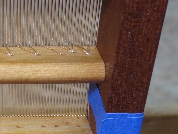
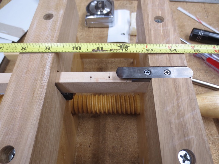
Eighteen identical spindle units are being installed to make a backing and facing for a 10″ x 15″ mould. One side of the unassembled mould frame has been marked with the preferred rib spacing and is being held in place while the spacing is transferred to the spindles. It’s being held between two other parts of the new system. That they can do double duty as clamps was a happy accident. The one on the right is designed to hold the shuttle in position just before it’s pushed (by a laid wire) through the openings in the wire above the spindles. The similar part on the left ‘catches’ the shuttle after it has finished guiding the wire through. There it can easily be picked up and moved back to its starting place.
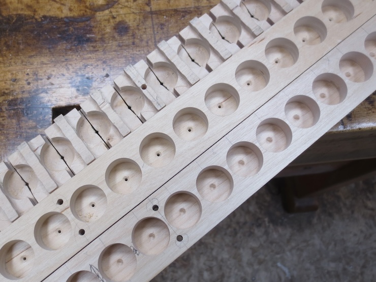
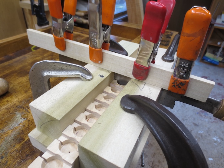
To transfer the spacing from the mould to the loom one edge of each unit is lined up with a mark then clamped in place.
The three on the right have been positioned. Additional ones can be tipped into place prior to clamping.
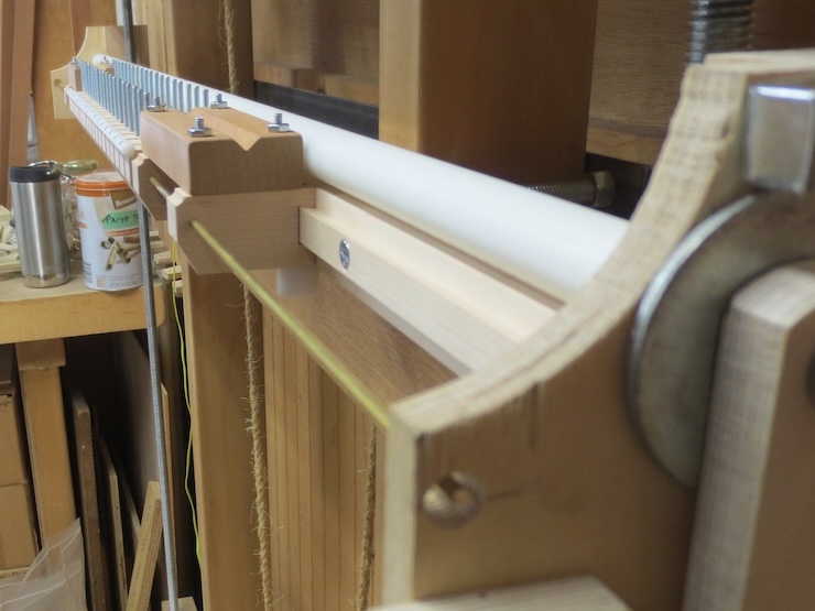
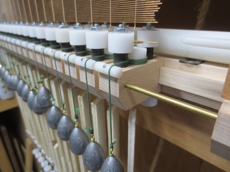
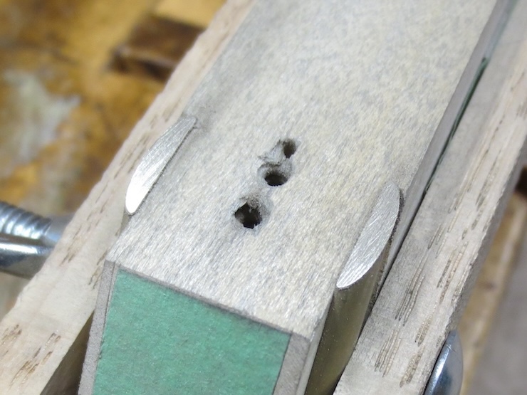
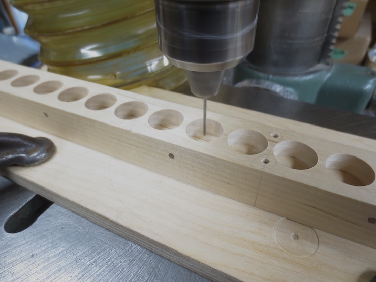
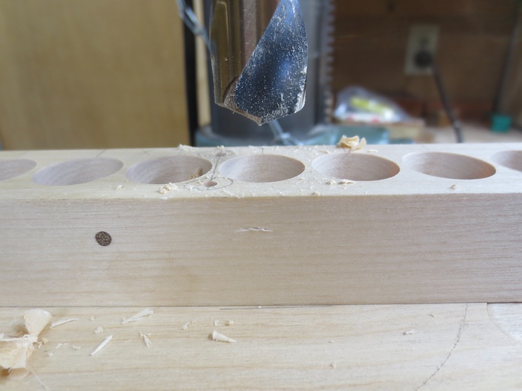
After all the spindles are in place the mould frame part is removed. A brass rod is passed through all of the spindle units to add an extra bit of security. If one unit should work loose it will still be held in place by its neighbors (though I haven’t found this to be a problem yet). These holes are drilled .003″ larger than the 1/8″ brass rod so it can easily be fed through by hand. It was more convenient to use two segments of rod. One was inserted from each end, placing the joint within one of the spindle units.
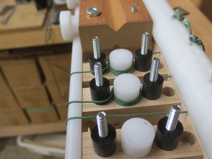
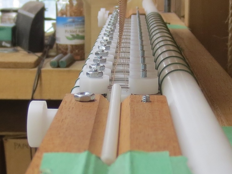
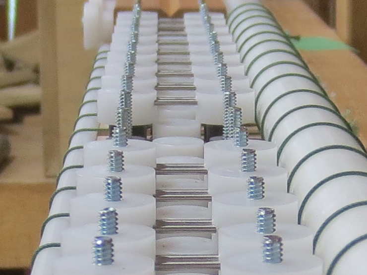
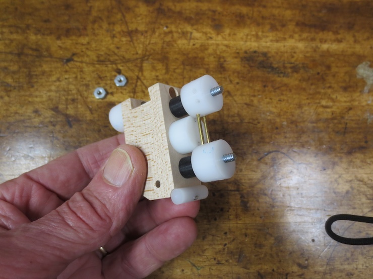
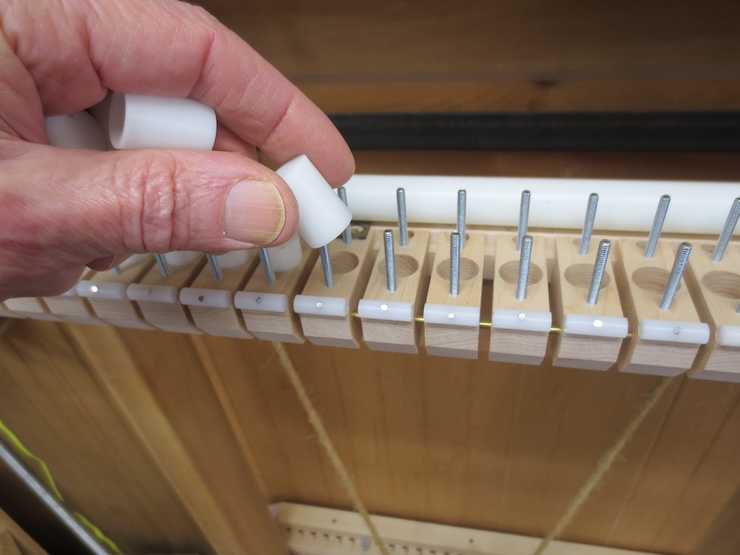
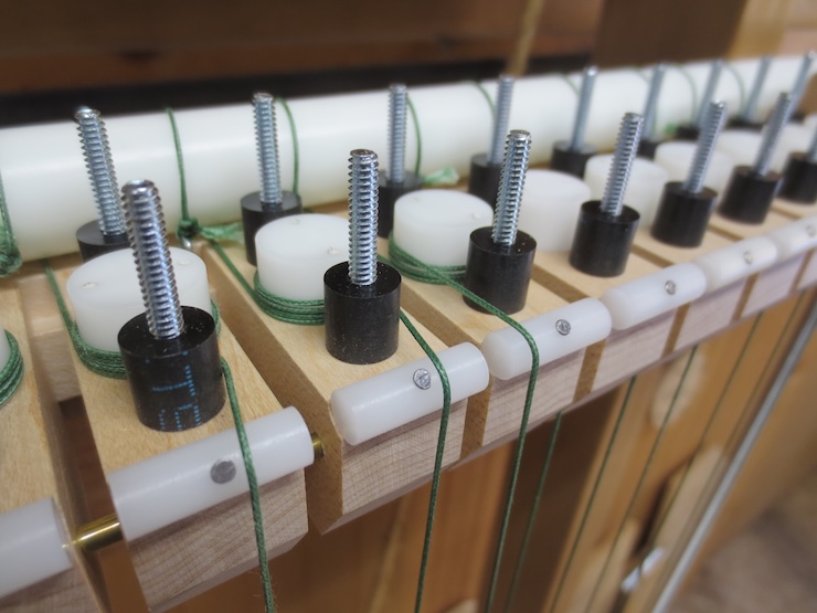
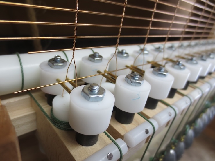
Now the spindles are dropped into place. This photo makes it look like the spindle goes over the threaded stud but it really goes into the hole.
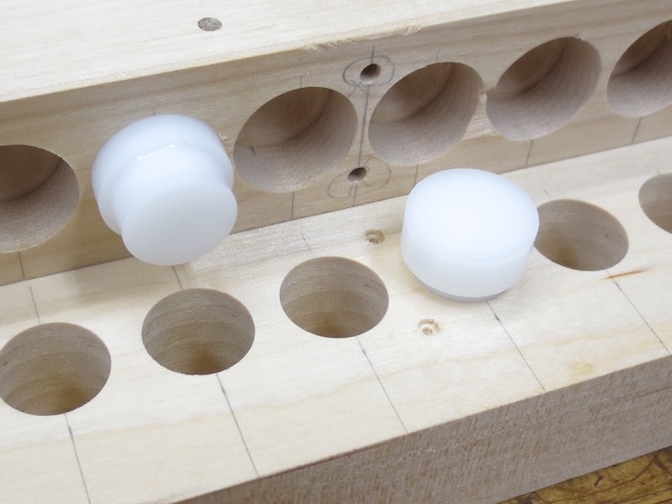
The (white) spindles stick up exactly 3/8″ (.375″). The (black) spacers are longer (.385″) to hold the wire support parts a little above the spindle tops. When the parts are tightened down the gap will be small enough to prevent the drive cords from slipping up over the spindle top by accident. This is a problem to be avoided and this seems to be a good solution.
This new system makes many things easier but wrapping the spindles is a little more difficult with the studs and spacers in the way. On the other hand, the spindles won’t need to be flipped when changing over from making a backing to making a facing. Only the wire supports will be flipped so the spindles won’t need to be wrapped a second time.
Another happy accident was realizing that the cord can wrap around the front spacer. This puts it closer to the center of the spindle unit so it won’t fall off the edge.
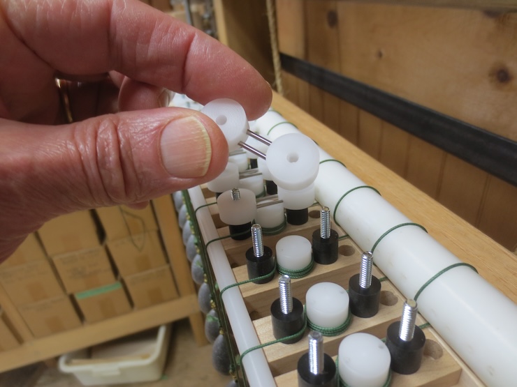
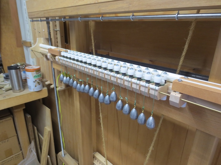
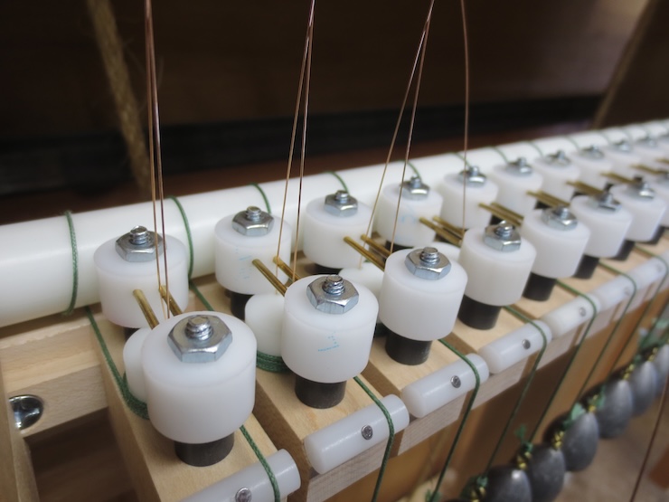
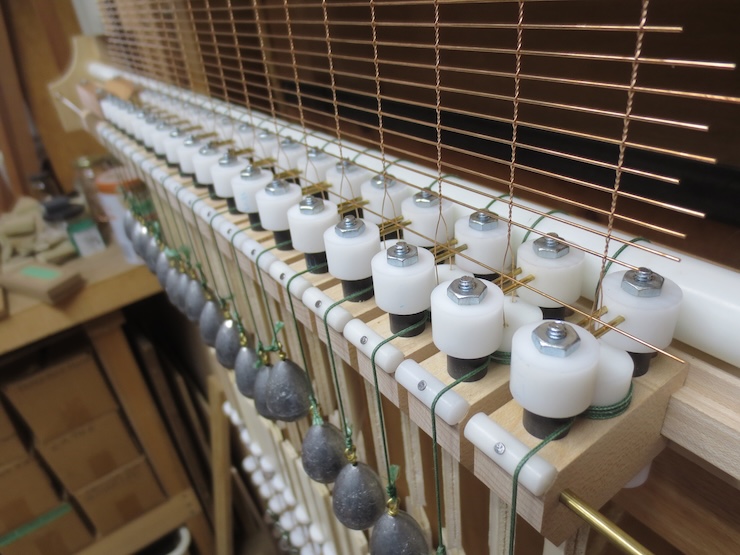
The wire support assemblies have all been placed over the spindles and are fastened down with hex nuts. These only need to be finger tight. The wire support rods have been placed in the higher position to make a laid backing.
With the new system it’s easy to stick the wires down through the holes in the spindles.
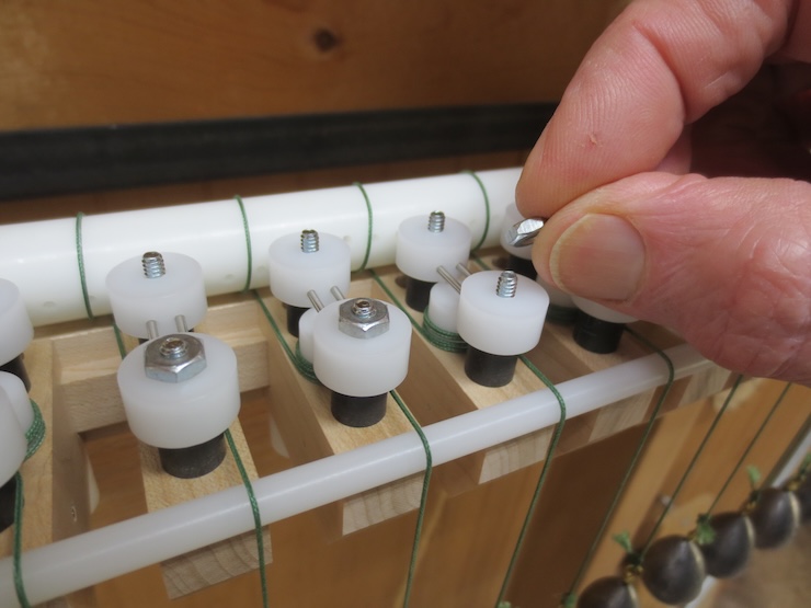
When making backing the shuttle rest needs to be elevated to match the higher support rods so the shuttle can slide evenly onto them. Here four 1/8″ thick nuts have been placed (not threaded) over the steel studs to lift the shuttle rest. I’ll make fitted shims in the future to make this easier.
The shuttle has guided a laid wire between all of the chain wire pairs. This works very well; there’s no room for the shuttle to stray off to either side. When the foot treadle is released the twists will settle down over the new laid wire. Then the twisting action will center the laid wire perfectly.
The backing worked well on the first try.
The first laid facing didn’t work out. The gap between the wire support rods was too small. I learned that if the gap is too narrow the soft, as yet untwisted chain wire gets distorted as it passes under the rods and can’t wrap tightly enough around the laid wires. After a number of tries a space of just under 1/8″ between the rods seemed to be best. The first two facings ended up being useless, but valuable as research. But all the laid wires were pulled out and used over again.
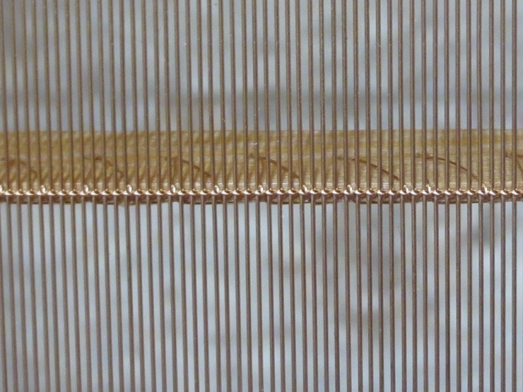
The final facing in progress.
Below the finished facing you can see the wide gaps between the wire support rods. I had previously assumed that it was necessary to make the gap narrow to keep the twists from slipping backwards.
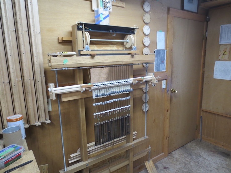
The seven wooden spindle racks visible in the photo now seem to be obsolete.
When using standard fixed spacings (7/8″, 15/16″, 1″ 1-1/16″ etc.) there is often a problem in adapting the spacing to the size of the mould. Spaces at the ends of the mould may be too big or too small. Now it is possible to simply divide the mould frame into whatever spacing is best without relying on any standard system of measurement.
This post will be added to as things develop. You may be interested in a new page on the main website: Tapping a Larger Hole.
I started making four of these presses in early 2015. For various reasons only one was completed; the partially shaped parts for the other three presses and floor standing tubs have been stored in my shop since then. I have recently resumed work on them.
An earlier batch of these.
The laminated blanks have been glued up since 2015.
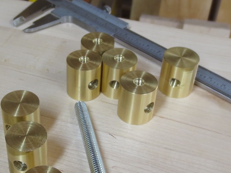
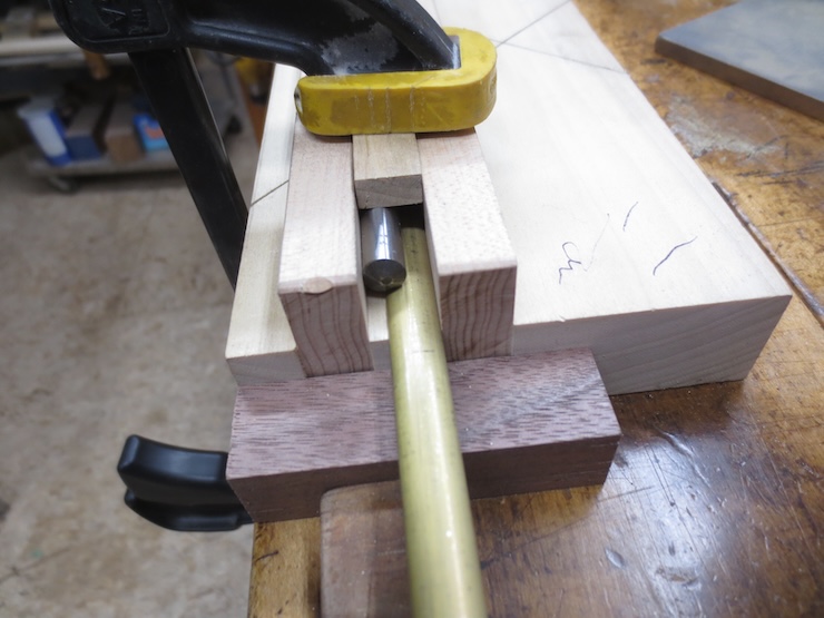
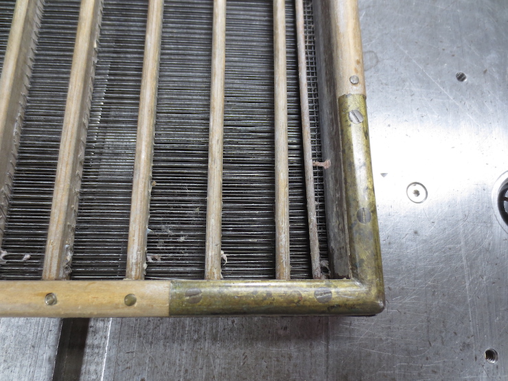
I have found three shapes of extruded brass that are suitable for making braces to protect the bottom corners of moulds. The largest size is a true half round 1/2″ wide and 1/4″ thick. The other two are roughly half oval. One is 1/2″ wide and about 1/8″ thick and the other 3/8″ wide by 3/32″ thick.
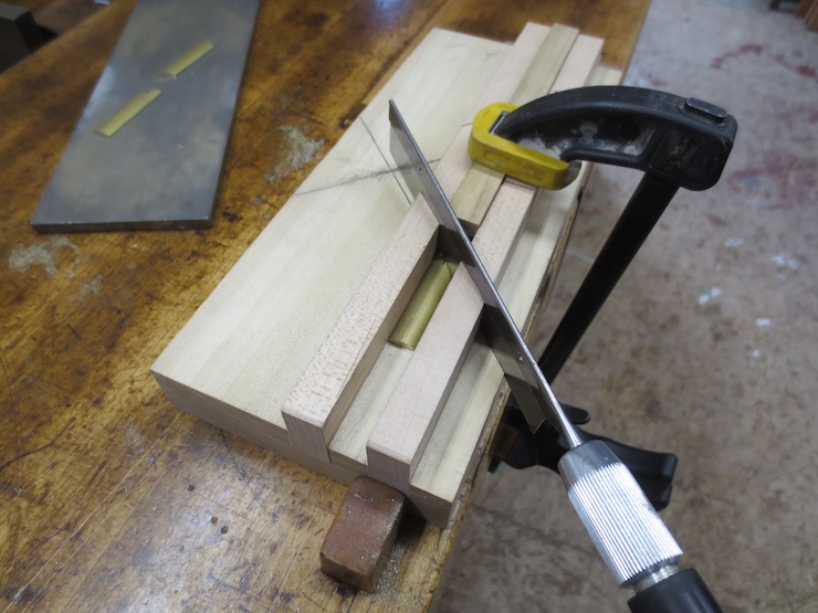
I made this sawing jig to miter this material with a razor saw. The fences are set into grooves and fastened from the bottom with round head screws and washers. This allows the 45 degree ends to be re-shaped and re-set when they get worn.
A piece of drill rod pushes the narrower 3/8″ stock against the back fence when clamped. The two wider sizes fit snugly between the fences but are also clamped using the same arrangement.
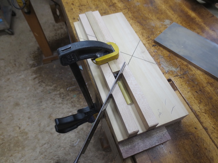
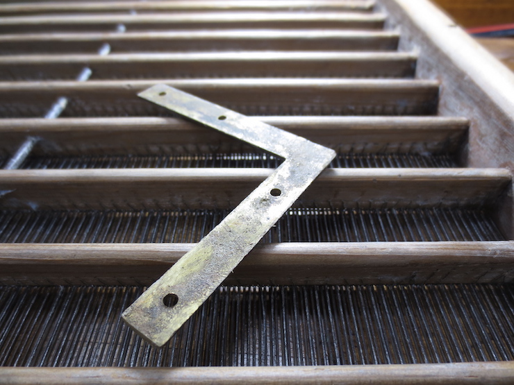
A single length makes two parts after a miter is cut. For this smaller material I used a piece just under 3″. This produces an L shaped brace with sides about 1-5/8″ each way.
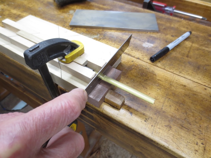
It takes two of these lengths make two L shaped braces because the miters must be cut opposite ways to get the mirror image parts needed.
Starting the first saw cut.
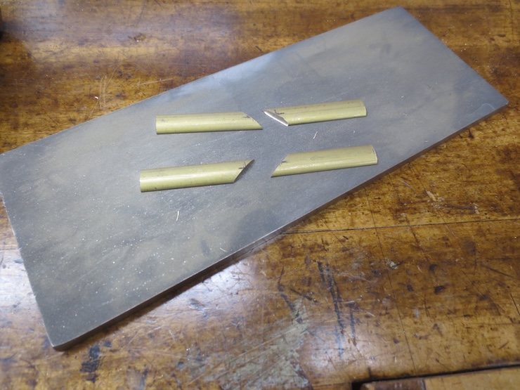
Two identical parts result.
The second part must be cut opposite from the first.
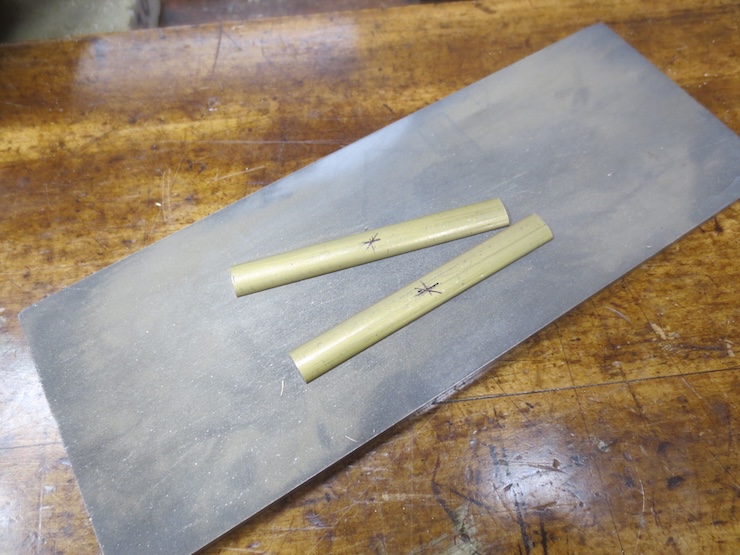
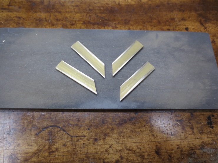
Now the pieces are lapped flat and any burrs are removed from the bottom edges. Slight burrs on the curved top surfaces are left alone.
Flat bottom surfaces are important for shaping tight fitting maters. If the stock has a slight bend it can be gently hammered flat after placing a thin shim under one end.
This is a jig that I made to lap the miters. Opposite sides of a single brace are placed in the jig and clamped in place; the far one can’t be seen here. The white plastic stop aligns the ends at the same height.
The recessed margin of the stop places the miters a little above the jig.
This end is shown ready for lapping.
And the opposite end is also ready. The miters are all raised the same amount so the diamond plate doesn’t touch the wood.
Lapping the miters.
The right hand part is not completely lapped.
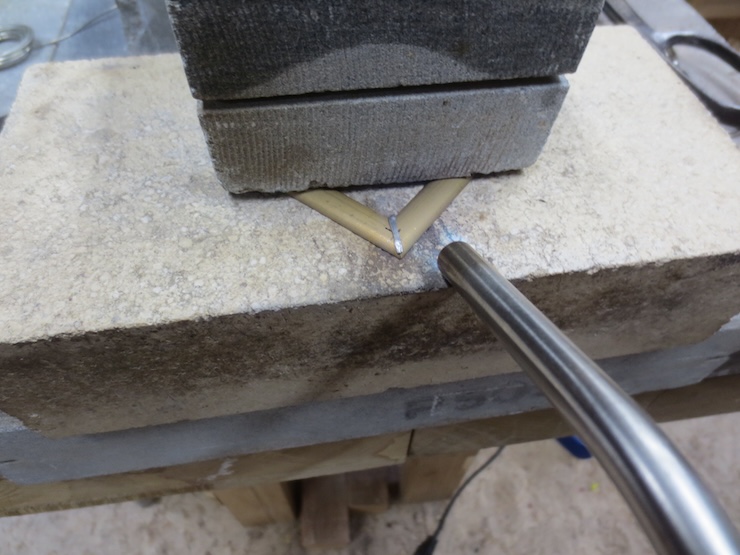
A little more work with the lapping plate brings all four ends a little lower and they are now ready to solder.
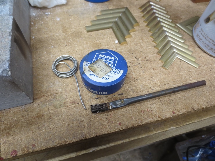
After experimenting quite a bit I found this paste flux to work best. I apply a thin layer to the freshly lapped miters while avoiding the top curved surfaces. (The price tag tells me that this tin of solder cost 65 cents and was purchased at a Coast to Coast hardware store. From these clues I deduce that it is about 45 years old.)
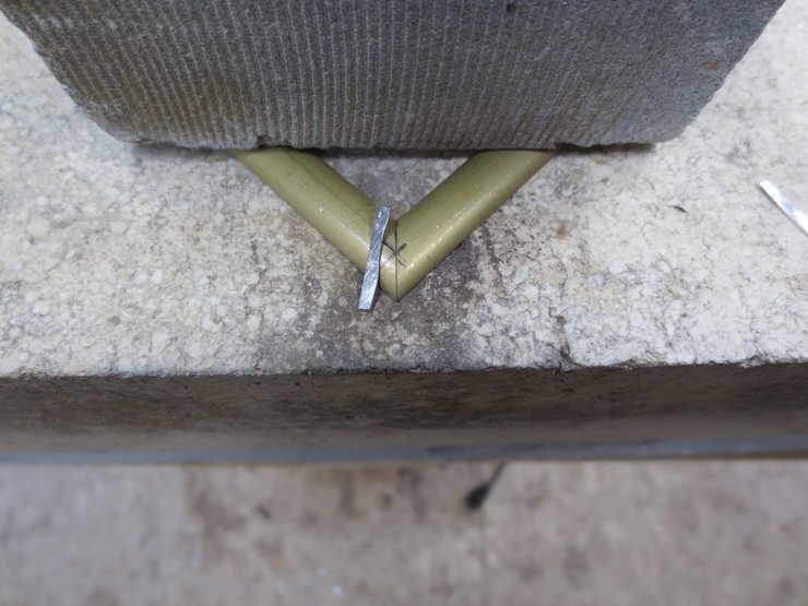
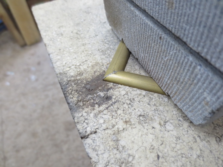
I looked for a firebrick that was very flat and ran the diamond plate over it to make sure. (This has an added benefit of scouring out the soft brass particles that clog the plate.) I square the brass parts and hold them in place with the weight of another brick, a piece of soapstone here. The brick is elevated on the far end so it only pushes down on the brass parts at two points along its front edge.
(After the joint is soldered the parts go out of square by a fraction of a degree. I think that when the solder flows in it widens the joint just a bit. This causes each half to pivot very slightly at the spot where the upper brick is holding it down. This makes the final angle of the braces very slightly sharper than 90 degrees. Aligning the parts with a slightly obtuse gauge (rather than the one shown) might correct this though the error is too slight to be a real problem.)
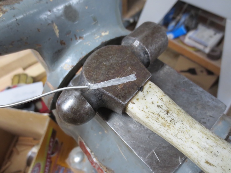
Solder can be hammered flat and cut into strips to make it easy to lay a piece over the joint.
Here it has been split with tinsnips and will be cut to approximate length.
This is plenty of solder to fill this joint.
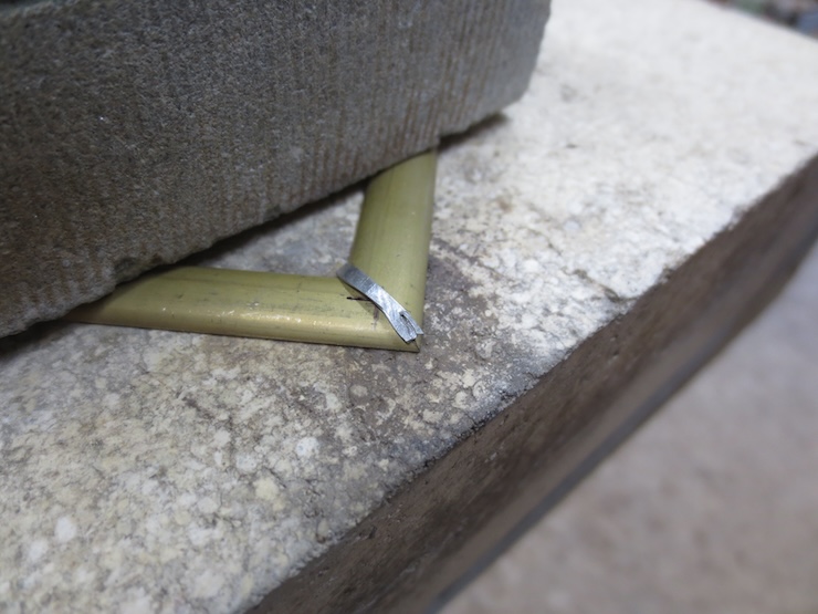
Being flat it is easy to form the solder to rest over the joint.
I eventually learned that a very low flame is best. I start at about the middle of the exposed parts and switch back and forth every few seconds. When the solder starts to melt I move the flame closer to the joint. The torch is actually resting on the firebrick, heating it as well.
When the solder has flowed into the joint a quick brushing with a cheap bristle brush gets rid of most of the excess solder. For my first experiments I was cleaning the entire part with alcohol, using liquid flux and also using a much bigger flame. The solder ran all over and needed a lot of filing. Many of the joints weren’t well soldered and had to be re-worked. The newer method results in a good joint with minimal cleanup needed.
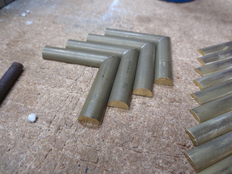
I started with the small ones and you can see that they have seen much filing and sanding with all the re-working I had to do. The big ones were made after I discovered the better way. Leaving the curved surfaces alone reduces clean up. Presumably excess solder doesn’t stick as well to the oxidized surfaces.
The heavy material is very substantial, weighing a little under 1/2 pound for a set of four 2-1/4″ x 2-1/4″ brackets! I’d be hesitant to use these for anything but very large moulds. I think the braces function more to prevent wear than to actually brace moulds square.
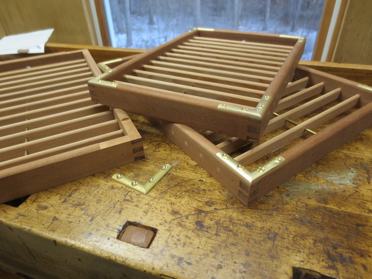
I would prefer these thinner ones for most moulds; they only weigh 3.9 oz. per set as opposed to 7.5 oz.
The small ones come in at only 1.6 oz. per set of four. These should work well for smaller moulds. I haven’t gotten around to drilling any of these sizes for screws yet.
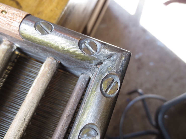
This solder joint is a little sloppy!
This one is a casting.
The same casting shown from the back.
This corner brace may have been sawn from flat stock and then shaped with files.
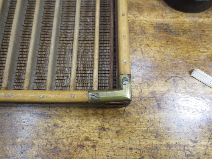
The light weight braces installed on a few small moulds.
Note: This information may be obsolete as explained by Post #63.
This post will try to convey information needed to make the most complicated part of this mould maker’s loom. It’s very long but the amount of detail should help the aspiring loom builder. For those not interested in actually making a loom skimming the photos and text may give a better understanding of these parts. Their functions are explained more clearly in earlier posts.
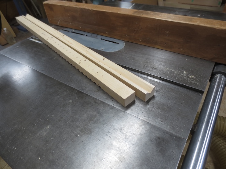
The making of two new spindle racks and matching wire troughs are documented here. These are the major parts of the twisting mechanism, both made of wood. When finished and equipped with the usual additional parts (weights, spindles etc.) this loom will be able to make two new chain wire spacings 7/8″ and 13/16″ apart.
Layout
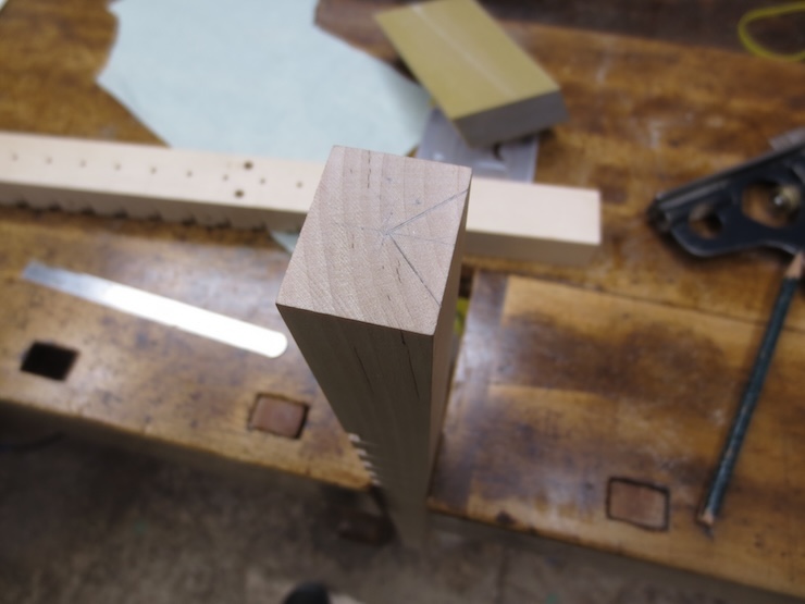
Blanks are prepared with dimensions of 3″ wide and 1-1/8″ thick for the spindle racks and 1-1/4″ wide and 1″ thick for the wire troughs. These should be made with care; straight without twist, sides parallel and angles square. The full-length version (the only kind I’ve made before) uses two pieces cut to exactly the same length (42″ for this loom). I’m trying something new with these two new ones. Both are only long enough to make a mould facing 24″ wide. But the principles are the same and the methods can be used for any length. These two wire troughs are longer than the spindle racks and stick out at each end. This will simply make it easier to feed the laid wires in from the end.
These blanks are yellow birch, a medium density, even grained, easily worked wood. Other suitable woods might be soft maple, cherry or walnut though this is not critical; my original loom, used for years, had parts made from pine.
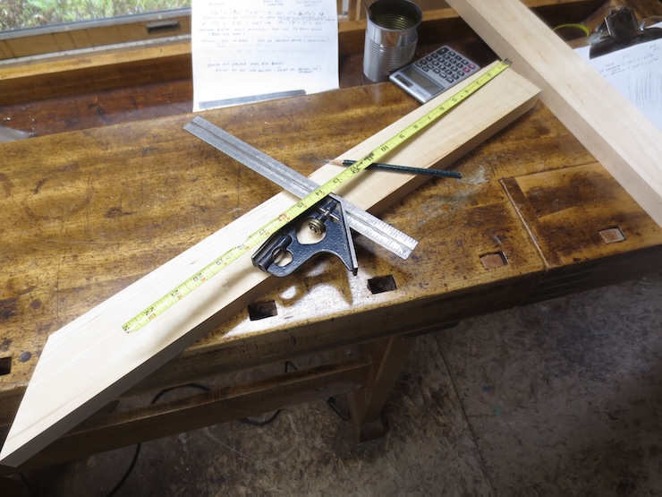
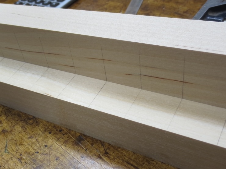
The chain wire spacing is carefully laid out on top of the spindle rack using a square and sharp pencil. Here the wire trough has been laid on its side and clamped in place while the marks are transferred to it from the rack.
Preparing for Attachment to the Loom
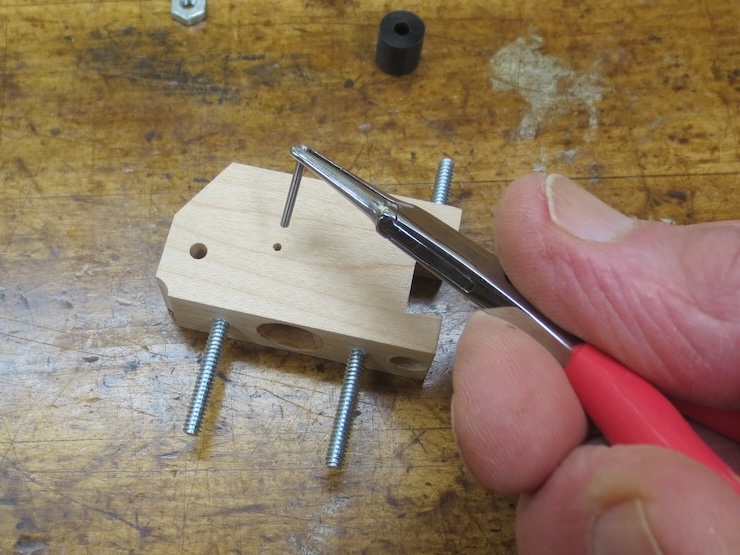
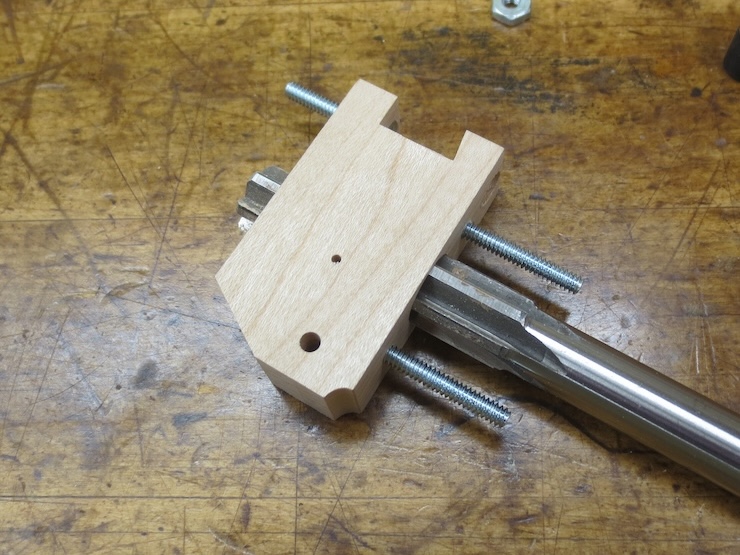
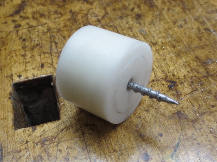
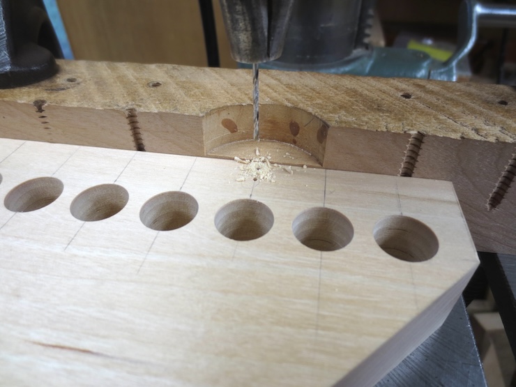
Three bolts will attach the rack to the loom. Acetal plastic plugs are embedded into the bottom, then drilled from the side and tapped for the bolt threads.
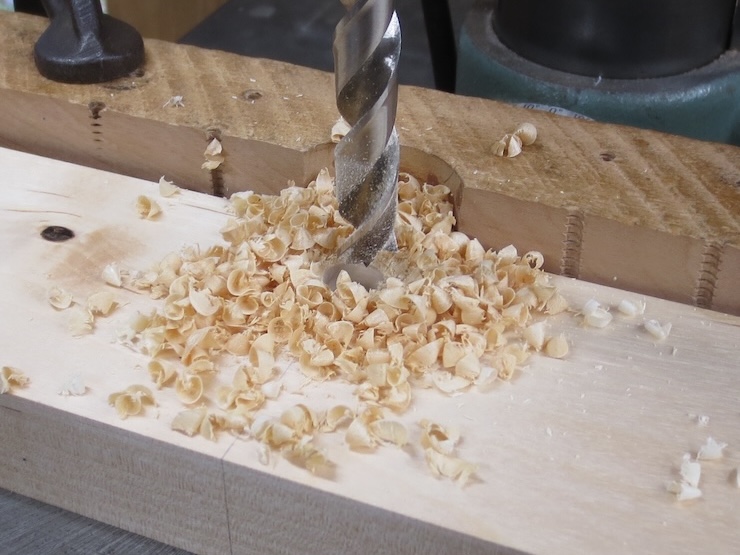
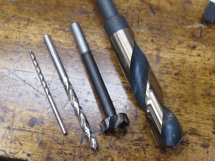
A 1/2″ brad point drill has bored a blind hole in the bottom of the spindle rack.
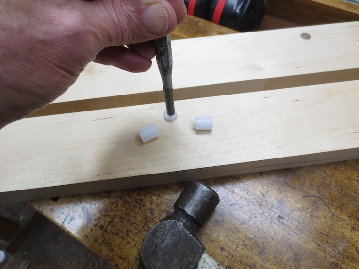
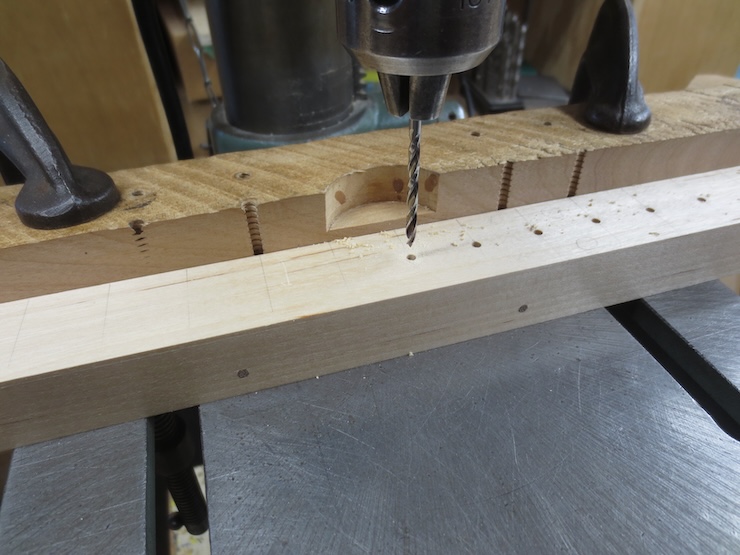
An acetal plug is tapped into place.
A 1/4″ diameter hole is drilled to the edge of the plug. This is followed with a #7 drill to make a hole through the plug.
These holes are then threaded with a 1/4-20 tap.
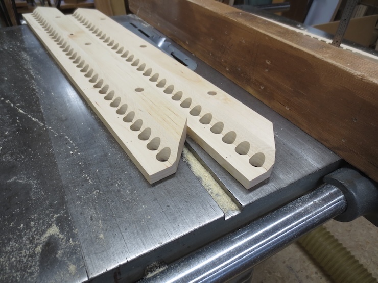
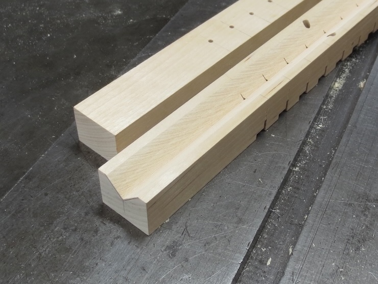
The part can now be securely bolted to the traveling beam of the loom. A full length twisting mechanism would use all five bolts; this shorter version uses only the middle three. The angled ends are the somewhat random result of cutting a long piece of wood in two at a 45 degree angle to get just a little more length along the front edges. This way I was able to make two spindle racks; both long enough to make a facing for a 18″ x 24″ mould, a fairly standard size.
Boring the Spindle Holes
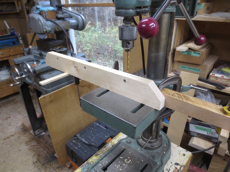
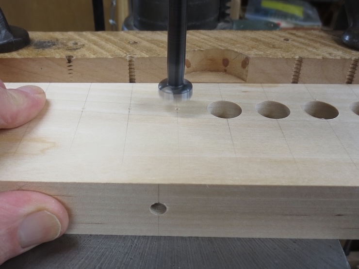
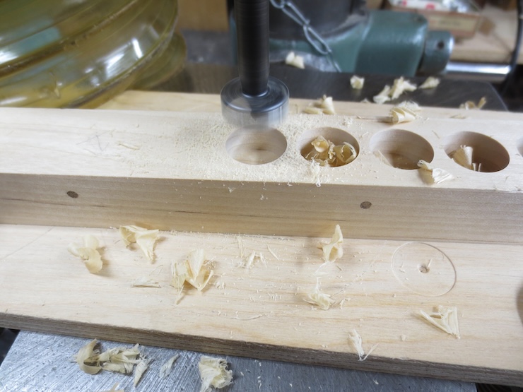
A fence is clamped to the drill press table to drill a line of holes centered exactly 1″ from the front of the spindle rack. The holes aren’t drilled all the way through since part of the front will later be cut away. If you look closely you can see that I pre-drilled tiny starting holes with a very small drill/countersink. This made it easier to get the holes centered right on the marks. The points of these wide, flat Forstner drills are not easy to see.
The rack is held firmly against the fence and down against the table. A 5/8″ high quality Forstner drill is being used to bore clean holes for the spindles to turn in.
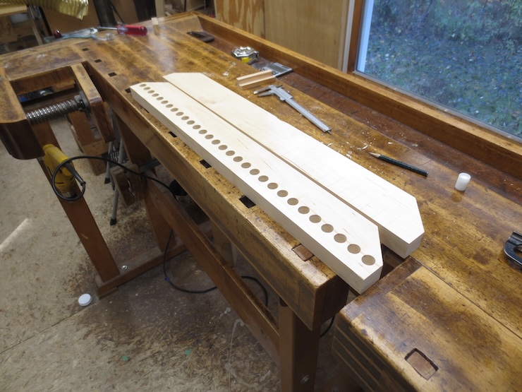
You can see that I was barely able to squeeze in enough spindles and needed the extra length created by the 45 degree cut. Identical cuts were made at the other ends for balance, more visual than functional.
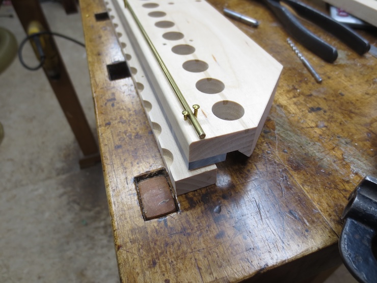
Laying out and drilling for ‘Reel Posts’ and for attachment of the 1/8″ brass rod
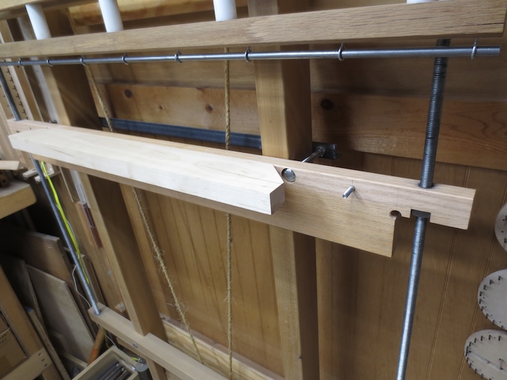
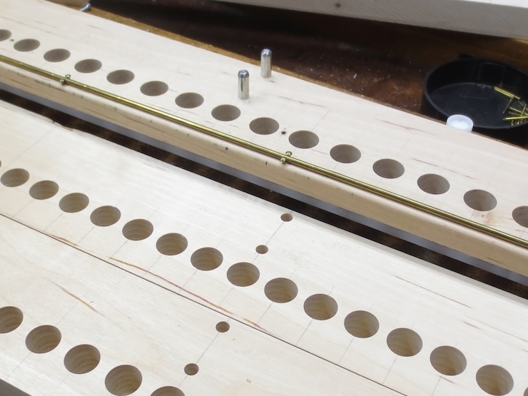
Holes are drilled for two pairs of 1/4″ steel posts. These will brace the reel that winds up the weighted strings to drive the spindles. The reel is made of 3/4″ acetal rod. This is perfect for this application but would be pulled forward too much by the weights if these posts weren’t here. A competed spindle rack with posts installed is shown at the back. The posts don’t need to be steel; brass or plastic would be plenty strong.
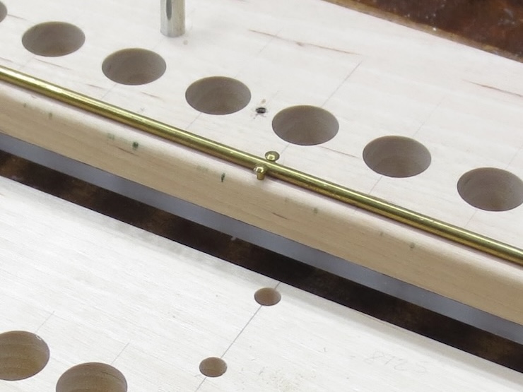
Pairs of small holes are placed at intervals along the front to secure a 1/8″ diameter brass rod there. This elevates each weighted cord at the front so that it won’t tend to cross over the previous wraps around the spindle. The cord starts low at the back and winds around the spindle in an ascending counter-clockwise spiral. After three turns it leaves the spindle higher up and is kept there by the height of the brass rod. The cords pass over the front of the rack and down where each is tied to a lead weight.
Later on brass escutcheon pins will be driven into the holes to secure the rod as shown above.
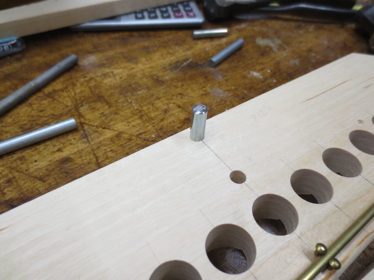
Indexing Holes for the Wire Trough.
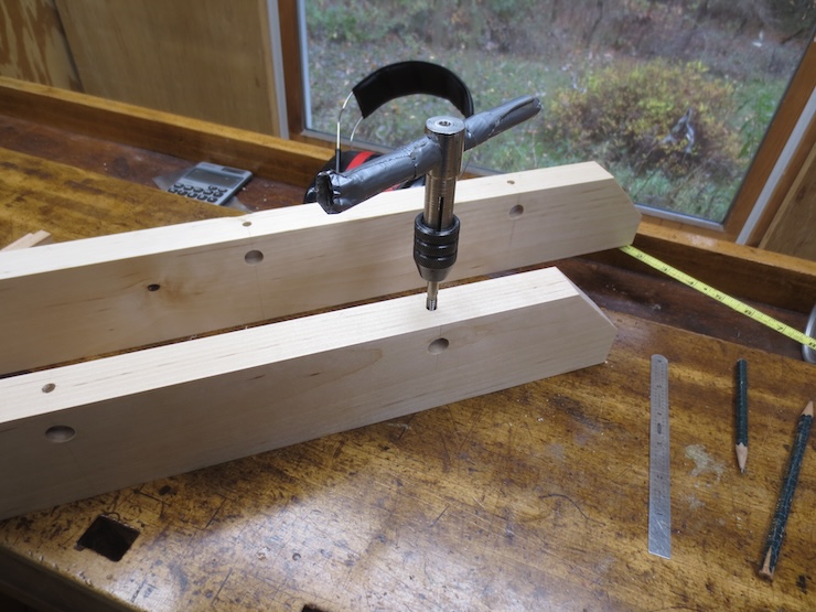
1/8″ diameter holes are drilled about 3/8″ deep into the top of the wire trough blank. These should be exactly centered front-to-back (with the help of the fence) and carefully drilled exactly on the pencil lines. I use magnification and sit low to the drill press table to ‘split the line’. Extreme care here will pay off many fold. I count nine different operations that will be performed for each spindle location; all will depend on the indexing holes and single pin to insure accuracy. This adds up to about 550 separate operations on these two wire troughs! (60 plus spindles x 9 operations each)
These index holes will be used to precisely line up a bunch of different holes and saw cuts. They need to be ‘perfect’.
1/8″ diameter and 1/4″ diameter brad point drills, a 3/4″ diameter Forstner and a 3/4″ diameter 135 degree twist drill will be used in making the wire trough.
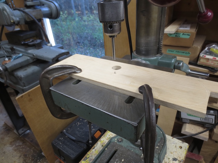
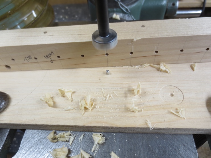
For the drilling operations an index pin must be set in the drill press. A piece of smooth, flat plywood is clamped to the table. Then a 1/8″ diameter hole is drilled partway through with a brad point drill. A number drill a few thousandths smaller is then selected to drill a smaller hole the rest of the way through.
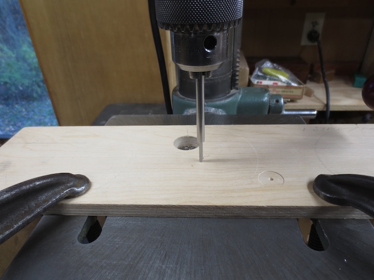
An 1/8″ diameter drill is picked out whose blunt end fits snugly but not too tightly in the index holes. It is rounded slightly with a belt grinder and buffed smooth. Here it is being forced into the ‘too small’ hole that has been prepared for it, using a drill bank chucked into the drill press. The drill press is switched off and is only being used as a press here.
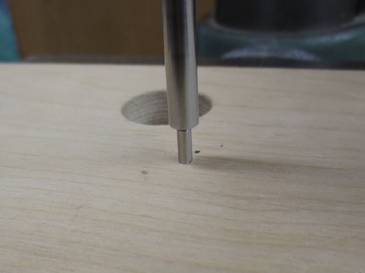
The butt end of the 1/8″ drill has become the indexing pin and is now firmly imbedded and exactly in line with any hole that is drilled above it.
Attachment of the Wire Trough to the Spindle Rack.
After the indexing holes have been drilled several pairs of holes are drilled for screws that will attach the wire trough to the spindle rack. #4 flat head wood screws will pass down through these holes and into the top of the rack. I use the indexing pin for this operation, too. First, correctly spaced 1/8″ holes are drilled from the bottom, out of sight here. Then larger holes are drilled from the top using the indexing pin as a guide. The heads of the screws will be sunk about 3/8″ below the top in the larger holes.
Boring Clearance Holes for the Spindles.
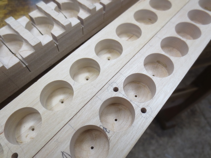
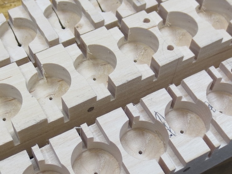
The reason the wire troughs have such an elaborate shape is simply to prevent the weighted cords from slipping off the tops of the spindles during use. This is a real headache when it happens. The extra time and trouble taken in making this design are well worthwhile. These 3/4″ diameter holes leave plenty of room for the cords to wrap around the sides of the 5/8″ spindles. Since the clearance holes completely cover the spindles notches will be cut to allow room for the cords in a later step. The tops of these notches will be just above the cords to prevent them from shifting upwards if the lead weights are accidentally bumped.
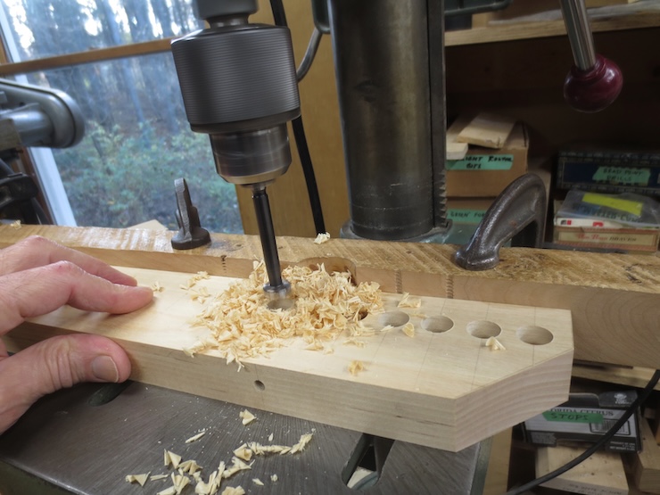
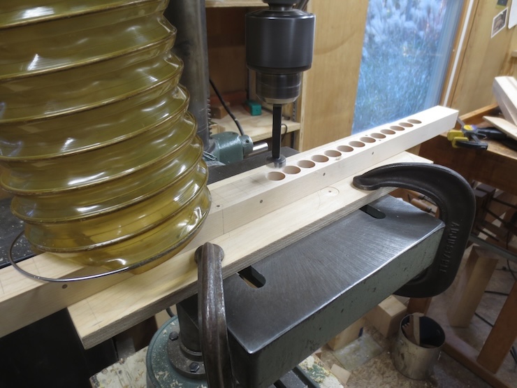
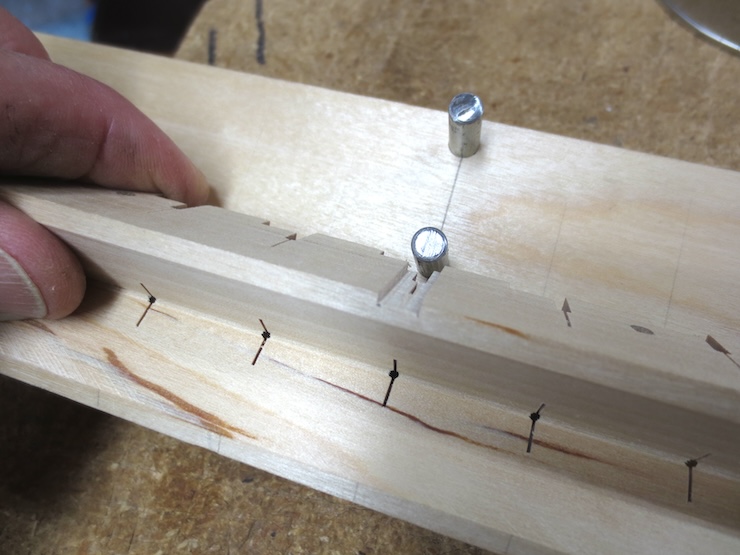
The wire trough is flipped on its back and 3/4″ clearance holes are drilled into it using the indexing holes and pin to line the holes up perfectly. The spindles will stick up from the spindle rack and into the trough exactly 3/8″. These holes need to be just a bit deeper so the spindle can rotate freely. I add about 1/32″ which indicates a total depth of 13/32″.
This shows how the indexing pin is used. The wire trough blank has been laid on its side with the index holes exposed. After blowing off the shavings the blank will be placed flat on the table with an index hole engaging the pin. When a new large hole is drilled from the top it will be precisely in line with the index hole below.
These clearance holes are very close together for the new twisting mechanisms. This is about as close as 5/8″ spindles can get without seriously weakening the wooden parts that hold them.
Earlier on I put in 1/8″ diameter dowels cross-wise every four spaces to strengthen the parts so they wouldn’t crack between the large holes. The dowels were driven into the drilled holes without glue. You can see the end of one of the in the photo above and five in the photo above that one.
A completely drilled rack lying alongside a completed spindle rack to help show the direction things are going.
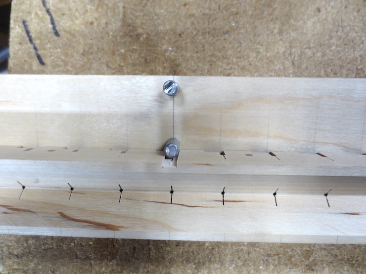
I next drill 1/16″ diameter holes a little deeper into the wood. Later these will show as a small opening where the V groove of the wire trough intersects the conical spaces over the spindles. The small holes will be also used to help gauge the fine saw cuts which will be made to create the wire engagement slots.
The 1/16″ holes are not yet drilled in the bottom piece.
Making the flat bottoms conical.
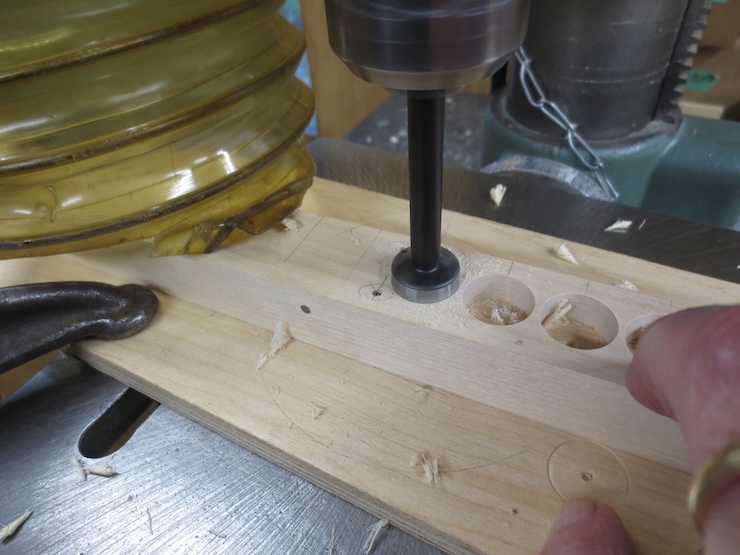
Forstner bits leave a flat bottomed hole. To give the wires room to twist above the spindles a shallow cone-shaped space must be drilled into the flat ‘bottom’ of each hole (which will become the top when the part is turned right side up). This conical space does not need to extend all the way to the sides since the wires leave the top of the spindles less than 1/2″ apart. A narrow rim around the edge of the hole is left flat.
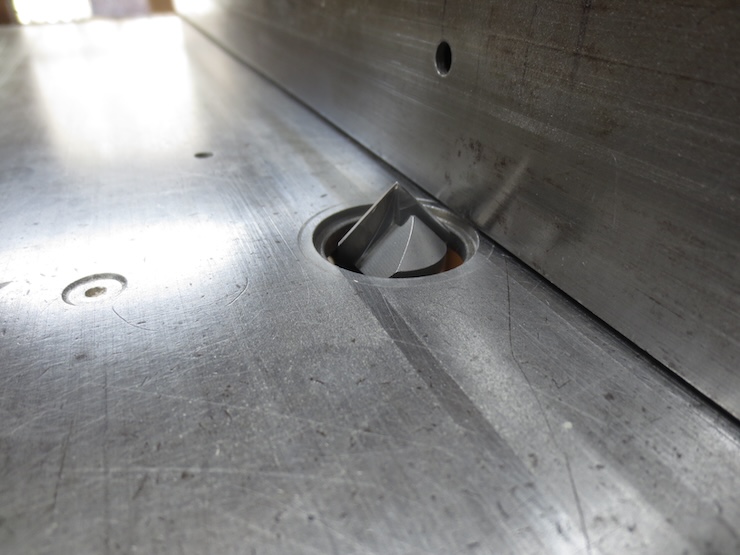
I purchased this 135 degree twist drill to create the cone spaces. The wide angle allows the chain wires to splay widely as they twist around the laid wires. This makes it possible to use heavier chain wire for a given laid wire spacing. A less obtuse 118 degree drill would likely be fine also. A 60 degree countersink would create a conical space far too pointed; laid wires in the trough would end up far above the top of the spindle and the twist angle would be very steep. In researching this post I learned that countersinks are available with angles as wide as 120 degrees. A 1/2″ diameter 120 degree countersink would work since the wire holes in the spindle are less than 1/2″ apart.
If the large twist drill leaves a small flat at the middle it can be judiciously removed with a countersink. This is visible in the photo above; slight flats are visible on the right and have been corrected on the left.
Aligning the Wire Trough to the Spindle Rack
The drilling of the wire trough is finished. Now the two wooden parts of the twisting mechanism are carefully aligned while extending the small holes for the attachment screws.
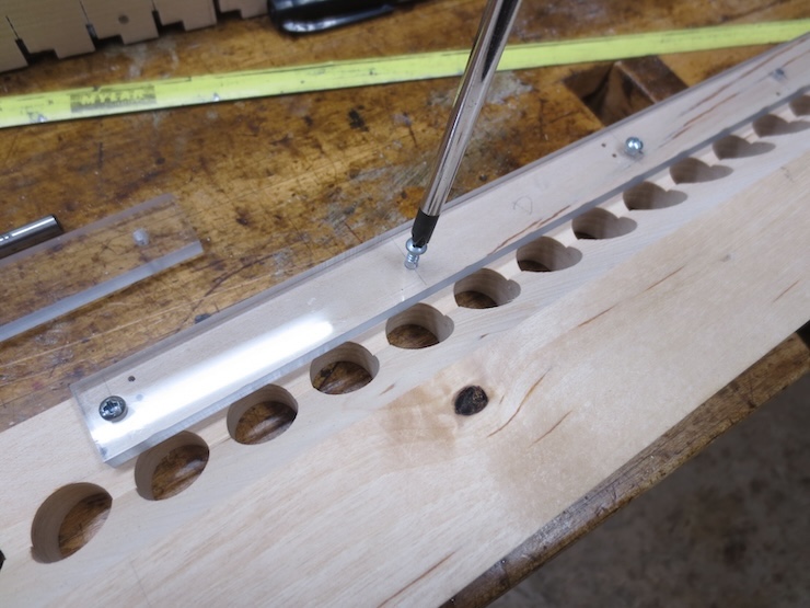
I made these two plastic parts to align the wire trough directly above the spindle rack while marking the small screw hole locations with a brad point drill as shown above. Careful measurement would also suffice. The centers of these barely started holes are carefully drilled to allow for the #4 screws.
Cutting Cord Slots in the Wire Trough
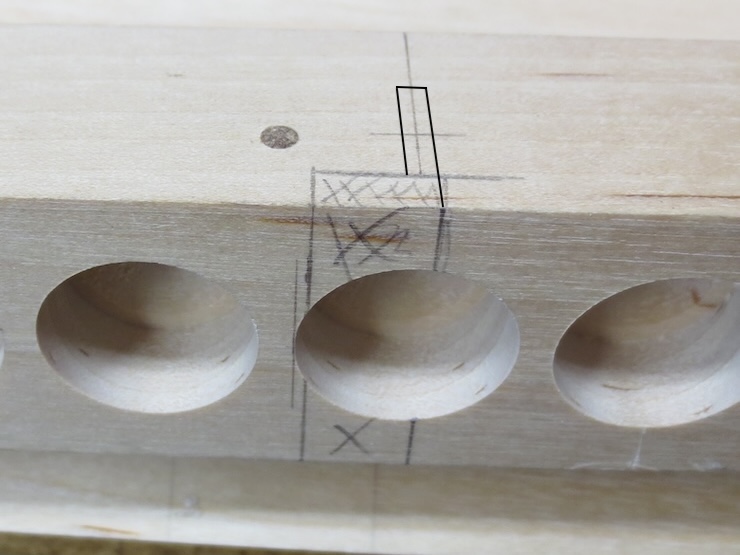
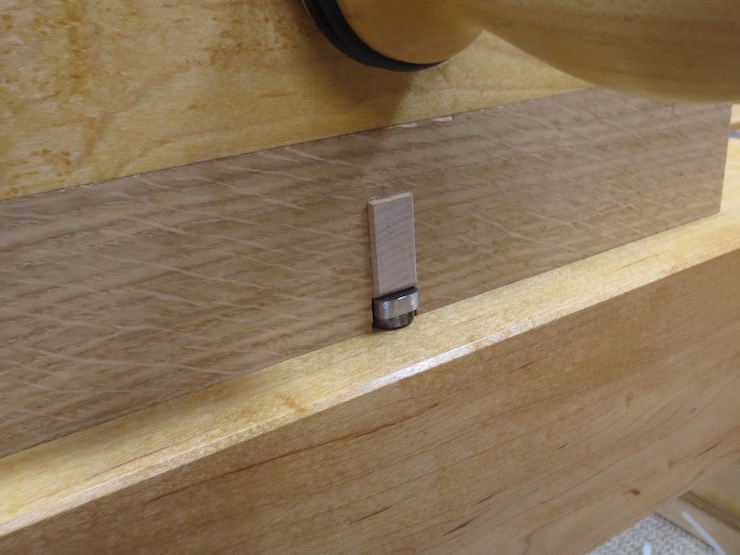
For each spindle location this area needs to be removed from the bottom of the wire trough to make space for the weighted cords that will drive the spindles. The narrow part indicated in black will be removed first; it is the start of hand sawn wire engagement slots that will be cut further up into the trough.
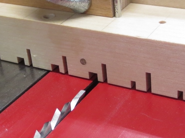
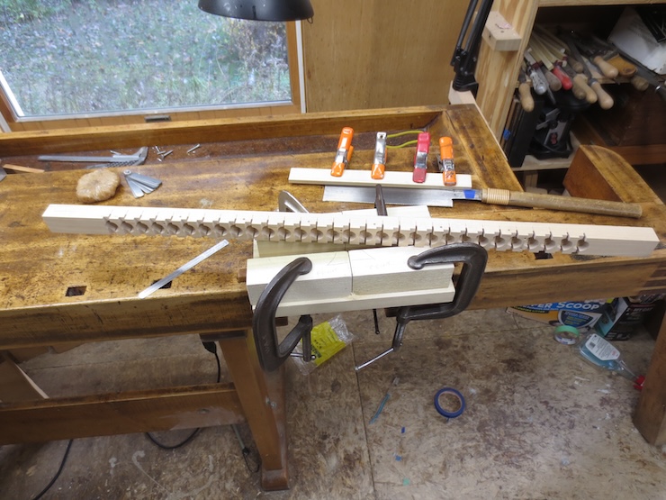
The drill that was embedded in the drill press table as an indexing pin has been removed and is now used to index slots being cut on the table saw.
The drill is moved to a new hole and pushed against the stop for each saw cut.
You can see how these slots are the beginnings of very fine cuts that will cut farther up into the trough. The top part is a completed wire trough.
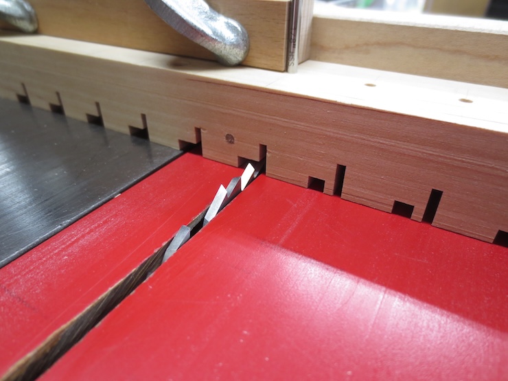
Multiple cuts are made to creat the shallower part of the notch. It makes room for the weighted cords that drive the spindles but also prevents the cords from ‘riding up’.
A third cut completes this operation.
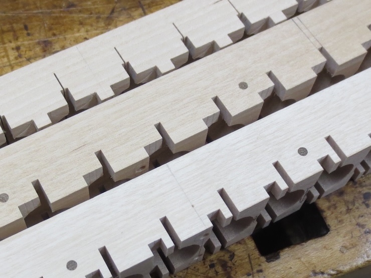
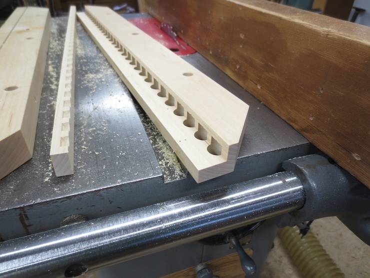
In the older version these slots (at the top) were symmetrical and could be used to make counter-clockwise twists if desired. (I have never done this and probably never will) Since these new parts pack the spindles so closely together the slots are made one-sided to keep the trough from getting too weak. As more and more wood is removed the wire troughs become fragile and somewhat flexible. I always store them screwed to the spindle racks when they are detached from the loom so they don’t get broken.
In the back a completed older version, in the middle the slots are complete, and at the bottom the shallower cord slot has not been finished. You can see how the asymmetrical version leaves more of the bottom surface intact.
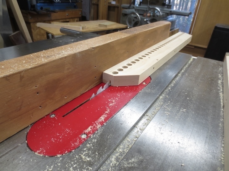
Sawing the Wire Engagement Slots
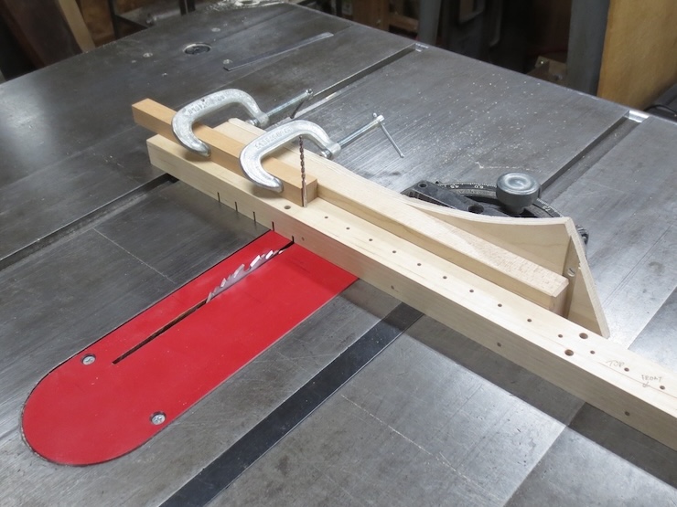
Once again, the indexing holes prove invaluable! A rounded bit of brass rod sticks up from the middle of this crude sawing jig and will be used to locate the saw cuts precisely.
A lot of head scratching and playing around with a set of feeler gauges yields a jig in which the trough can be lifted and repositioned to index the saw cuts precisely. The jig yields right angle saw cuts directly through the centers of the small holes. (It would have been smart to make an extra, scrap wire trough blank to help adjust the sawing jig.)
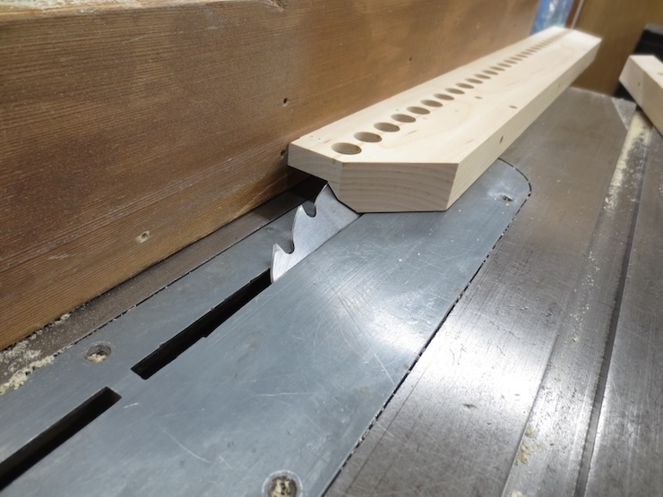
A partially sawn blank with some of the tools that are used. A strip of wood is clamped to the top of the Japanese style saw to stop the cut at the right depth.
Here the stop rests on top of the blocks, showing where the cut would be stopped.
The beginning of the cut.
The cutting action has been stopped by the wooden strip riding on the blocks. The cuts are about .025″ wide. The heaviest wire that will pass through these slots is .015″
The wire trough is nearly completed.
Final shaping of the Spindle Rack
The back of the spindle rack is left thick to provide a strong attachment to the loom. The front edge needs to be thinned to 1/2″ to support the spindles at that level.
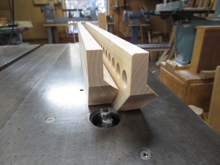
The waste has been partly cut away leaving the front edge exactly 1/2″ thick.
The back edge is cut at a 45 degree angle.
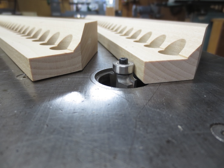
The front edge is rounded with a small radius router bit.
The piece on the right is now completely shaped.
Final shaping of the Wire Trough
A V shaped groove will be created in the top of the wire trough to guide and support the laid wires as they are inserted one at a time. The bottom of the V should be just deep enough to intersect the tip of the cone shaped clearance holes above the spindles.
First the waste is roughed out with the table saw set at 45 degrees.
The indexing holes are gone and the hand cut slots and the 1/16″ diameter holes have become visible in the bottom of the trough.
Final smoothing of the V groove is made with a 90 degree router bit. A slight flat will be left at the bottom of the trough. This is fine; the twisting action of the chain wires lift laid wires slightly and pull them to the center each time one is twisted into place.
Spindle Support Strip
A 3/4″ wide strip of polycarbonate supports the front 1/16″ of the spindles; holding them level. Screws are placed every three inches or so.
Final Details
A brass rod is cut to length and fastened in place by escutcheon pins driven into the previously drilled holes.
Short lengths of smooth rod are fitted into the holes to brace the reel.
Several corners needed to be chiseled off where escutcheon pin heads kept the trough from centering on the rack.
For the same reason shallow grooves were cut at the back to make room for the reel posts.
Now the wire trough is free to align correctly and be screwed down to the spindle rack.
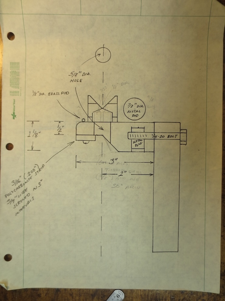
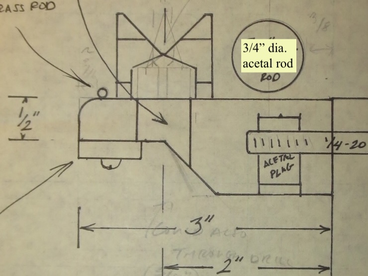
A cross section working drawing showing the parts we’ve been making and how they relate.
Installation and Testing
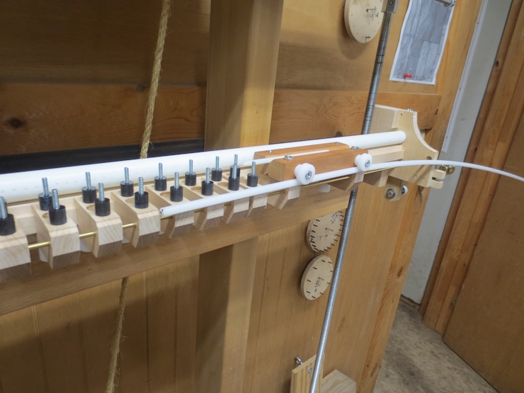
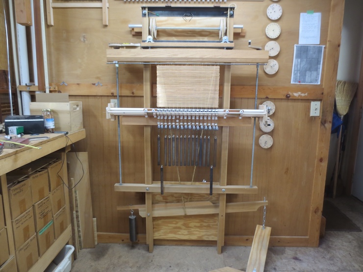
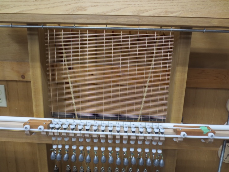
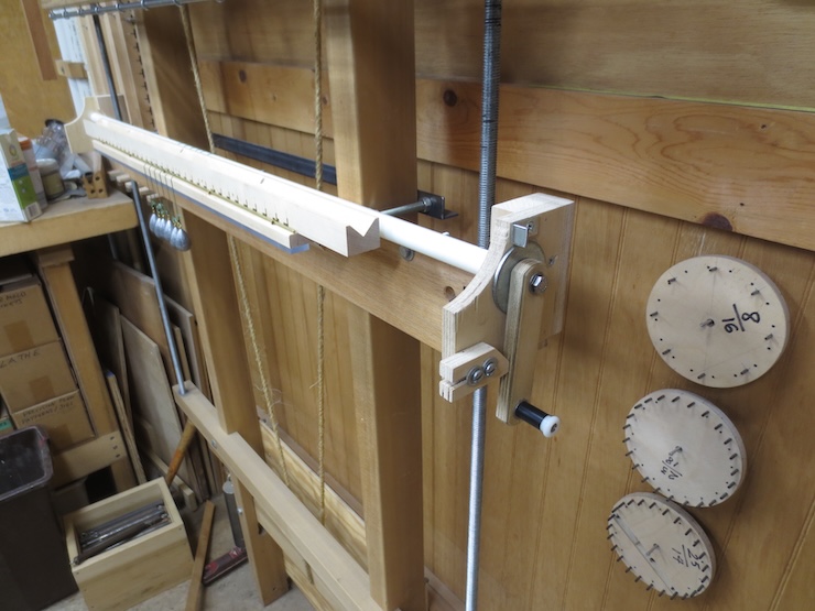
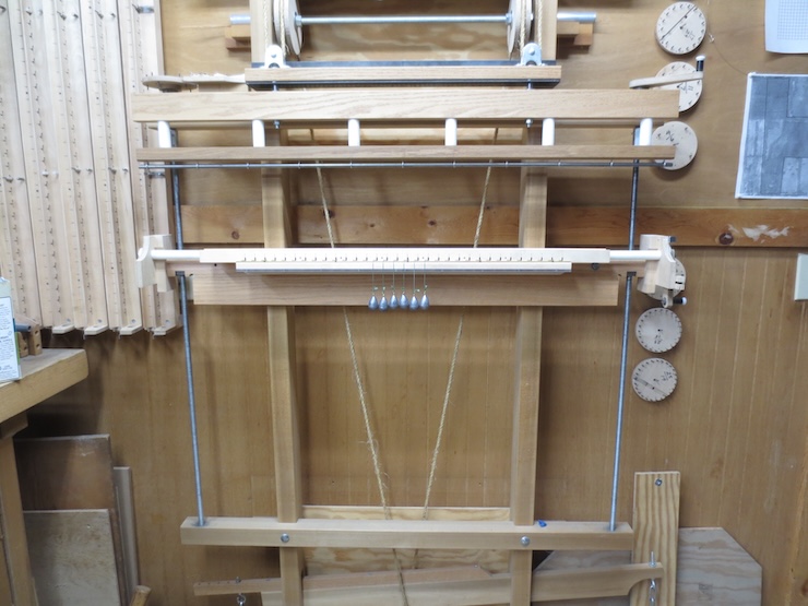
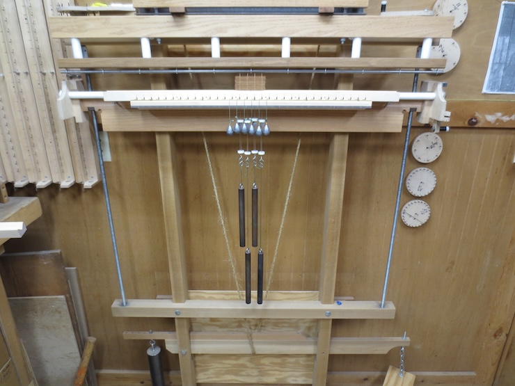
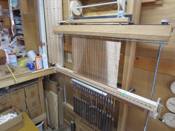
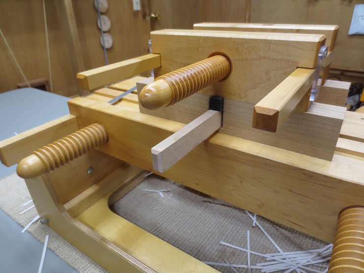
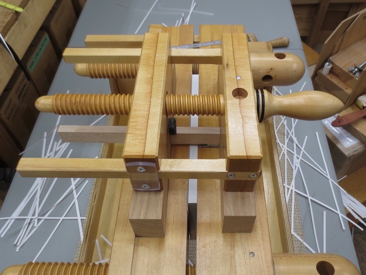
The finished 13/16″ twisting mechanism is installed along with a few spindles and weights for testing.
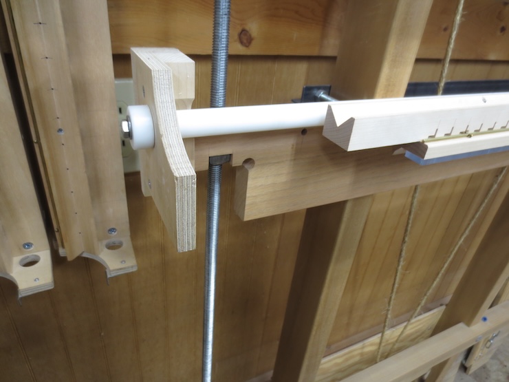
This shorter version required me to make new parts to hold the reel at the ends.
Here is the end with the fixed and adjustable stop to limit the turn of the spindles. If I had thought of this earlier I might have designed this loom so that the reel stayed on the loom all the time. The earlier twisting mechanisms require the reel to be re-installed each time a different chain wire spacing is required. (Which isn’t very difficult)
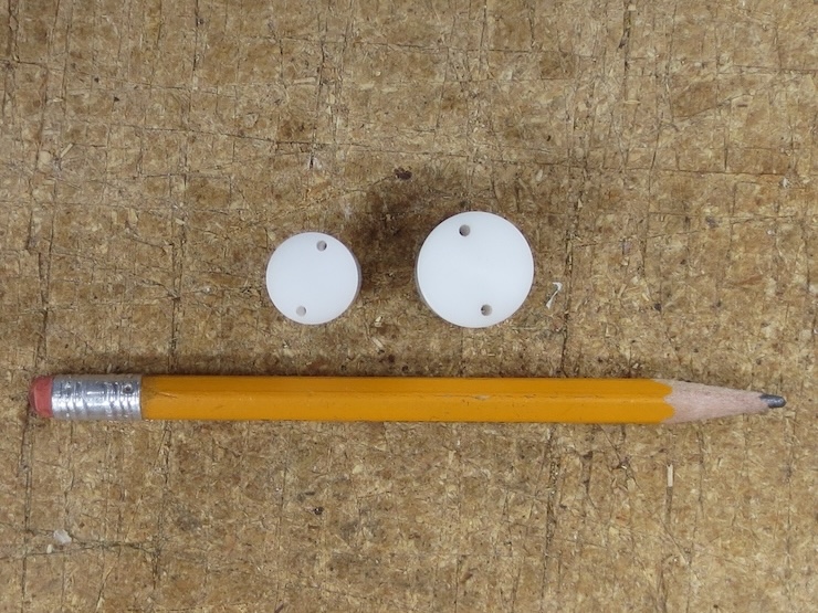
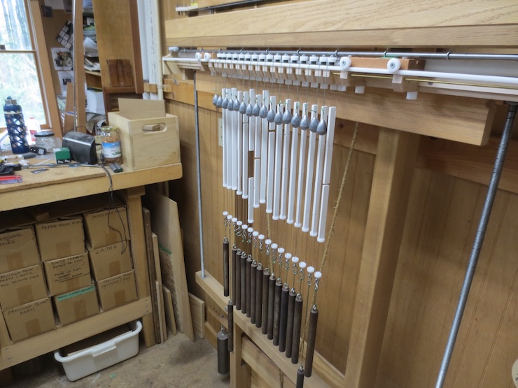
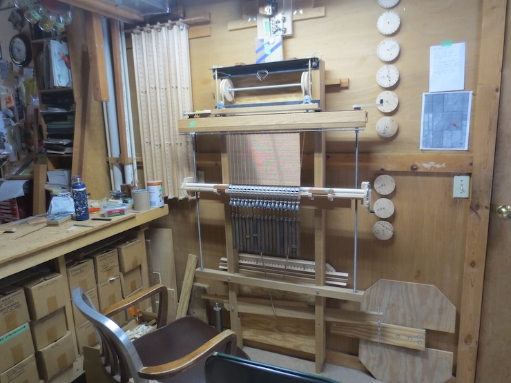
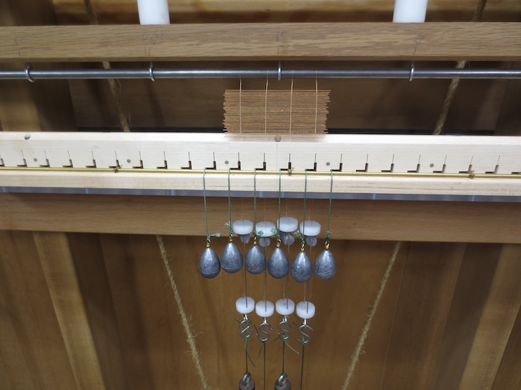
The lead fishing weights nearly touch and I had to make new wire slides that are smaller than the old wooden ones. These would have interfered with each other at this close spacing. The white plastic discs at top and bottom are 3/4″ diameter. 1mm fiberglass rod was used for the narrow splints that prevent twisting.
I have to hang every other weight on a longer string for these closely spaced chain wires. The weights are slightly magnetic and want to stick together.
Conclusion:
I hope that this is helpful for anyone wanting to make this type of mould maker’s loom. I now have seven chain wire spacings possible ranging from 1-3/16″ to 13/16″. I am looking forward to making a small mould with these very close chain wires and ribs. I am attracted to the (largely theoretical and mostly unrealized) subtle interplay between laid and chain wire sizes and spacing as incorporated into finished paper.
If I were designing a new loom I would likely separate the structures of the reel from the twisting head so that the reel could remain permanently in place as different twisting heads were installed. This had never occurred to me before this project.
Being able to make smaller twisting mechanisms could make it easier to produce moulds with custom rib spacing. In-between sizes, metric, or irregular spacing would be possible and full length mechanisms would not be required. A mould maker could keep dedicated twisting units on hand for standard size moulds.
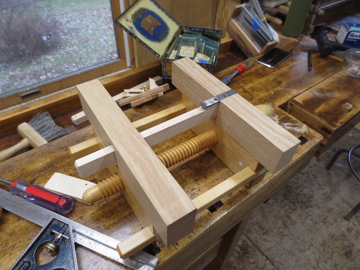
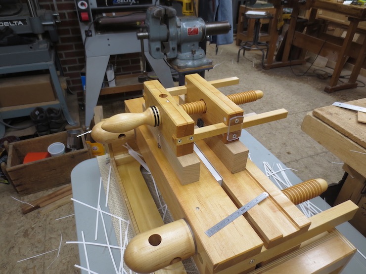
This is a more refined version of the plough discussed in an earlier post. I’m not sure it is all that desirable to have a “convertible” plough but this was an interesting experiment for me. In fact the larger version can easily be used to trim thin books. The tool is a little heavier but I’m not sure that is a significant drawback.
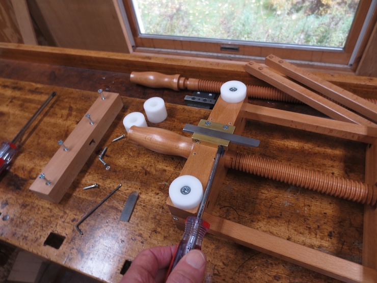
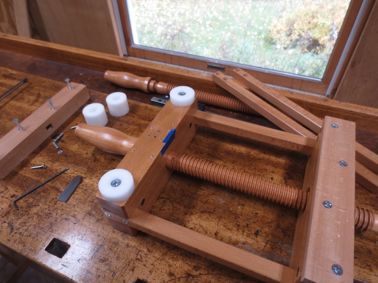
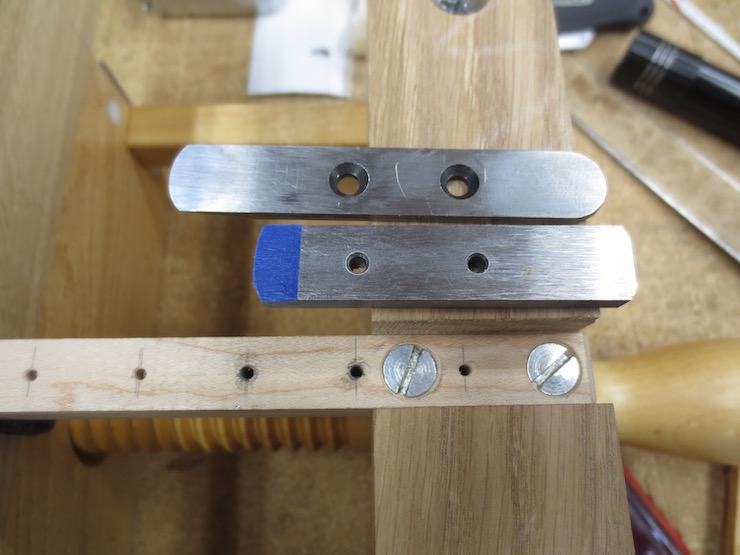
Laid out on the bench are all of the parts needed for this plough in either configuration. The plough is designed to work like a traditional bookbinding plow with a trimming capacity of about 2-1/2″. By substituting a set of parts it can be converted into a plough with a very wide cutting capacity of over 4″.
In the conventional mode the dovetail knife is clamped into a machined brass fixture. It can be set for different widths of cut by loosening two screws. Very gentle tightening holds the knife firmly in place. The knife is 1/8″ thick, a little more than 1/2″ wide and 4″ long.
Presses vary in how the tracking side of the plough fits. This plough doesn’t have a tracking strip yet but it might look like the one shown here.
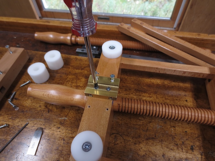
I will convert the plough from the traditional mode to the more experimental version. The first step is to loosen screws to remove various parts.
The blue tape is a shim that tilts the point of the knife down just a bit so the body of the knife won’t rub on the freshly trimmed pages.
These slide discs are sized to lift the knife side of the plow enough that the knife clears the press. These are removed since the new arrangement will require thicker discs.
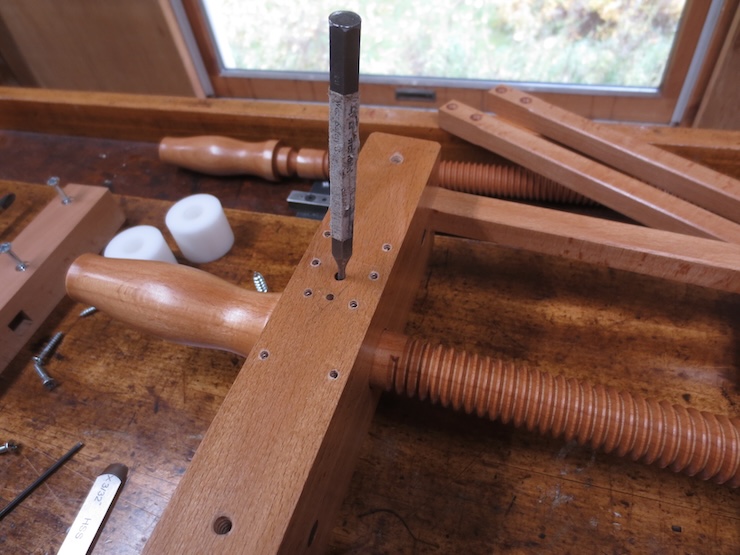
The steel pin that retains the wooden screw is pushed out.
The screw is backed out of the threaded part of the plough and removed.
Now the two guide bars are removed.
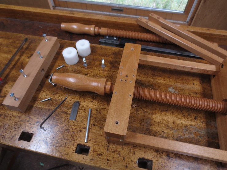
Here are all the parts that have been removed.
The two parts of the plough body are ready to receive the alternate parts.
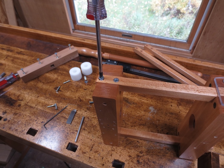
Longer guide bars are installed.
A longer wooden screw is threaded into place.
The steel retaining pin is re-inserted.
The long screw is now locked into the plough but free to turn.
These parts will now be added.
The block on the tracking side is made of two layers with a carefully fitted notch for the steel bar to slide in.
As before this shows what the next step might be to fit this plough to a tracking groove in its press.
The other end of the bar is fastened to the handle side of the plough with four screws. The thicker slide discs have been secured with the same two screws that were used for the thinner ones.
These clamping screws are tightened with a hex wrench. Very little pressure is needed to secure the knife. This dovetail knife is smaller at 3/32″ thick and about 2″ long. It is a little easier to make because there is less metal to grind away. Both sizes of knife are re-ground from high speed steel (HSS) jointer knives. (A jointer is a woodworking machine.)
The knife clamping fixture is machined from acetal plastic. It is about 2″ long and can be positioned in five different locations along the bar with a pair of screws. These are also tightened with a hex wrench, but firmly. A small piece of masking tape lowers the point of the knife a little so the rest of the knife doesn’t rub.
Here the knife is set to cut about two inches of book width.
This shows the knife in relation to the slide discs. When the plough is right side up the tip of the knife will be about 1/16″ above the press. The knife holder can easily be shimmed down if a closer setting is preferred.
The complete plough from the bottom.
The plough seen from the top. I am not a bookbinder but I have used the plow in both forms. I believe that it works very well.
Two Wires Instead of One for Very Fine and Single Faced Laid Moulds
Very fine laid moulds and single faced laid moulds can benefit from having closely stitched laid facings. Shortening the distance between stitches gives the delicate chain wires more protection from being stretched or bent. Especially in the case of single faced laid moulds it also helps the wire facing to lay smoothly on the ribs. A problem with this type of mould is that the laid wire facing is likely to bulge a little between stitches because the wires are fastened directly to the wooden ribs. The wood is somewhat soft and tight stitches can press chain wires down into it, creating humps between stitches that cause uneven formation. Closer stitching reduces this effect.
But when stitches are close a longer sewing wire is needed and this makes it more difficult and time consuming to sew. The wire is put through more steps since for each stitch taken the entire length of wire must be pulled through the wires in the facing (twice; once up and once down) and through the next hole in the rib. The small diameter sewing wire starts out strong and flexible but tends to stiffen and weaken a bit as it is ‘worked’. It should be handled carefully in order to keep it as fresh as possible but wires do break, especially if they have been allowed to kink (which stresses the wire severely at that point).
For these reasons I’d be inclined to use the following method for large, fine laid moulds, single or double faced. Each rib can be sewn with two wires instead of one. Each length of wire must pass through only half as many holes, can be shorter and stays fresher. As a side benefit drilling fewer holes in the ribs should leave them a little stronger, too.
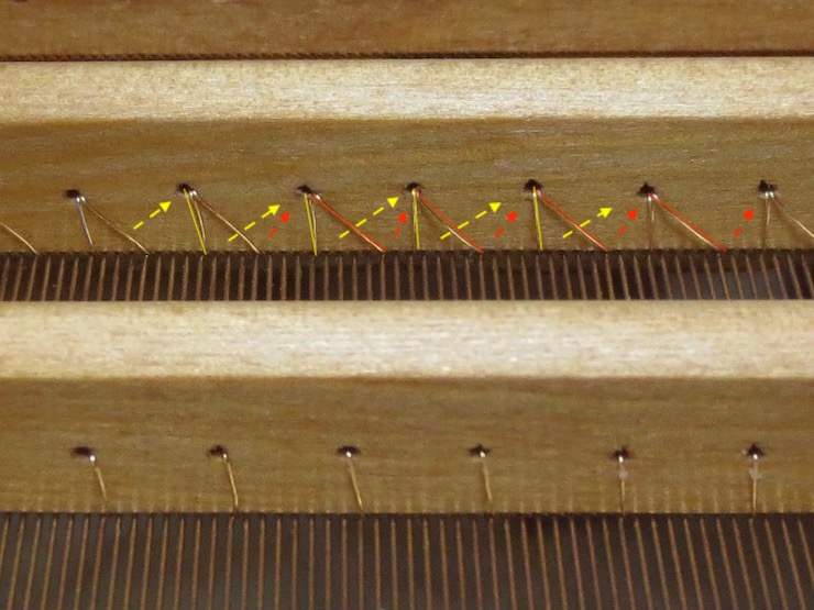
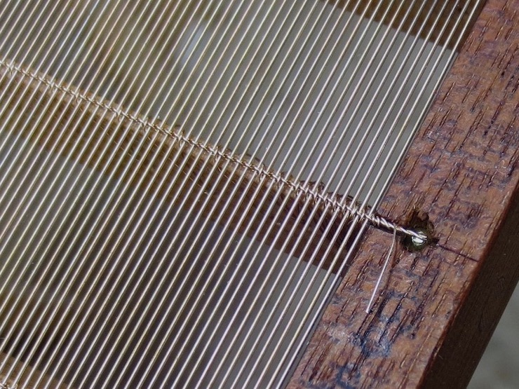
The front rib has been sewn once, following the rib hole spacing (which has been drilled to fit the wire count) to leave a stitch about every eight wires. The stitches are not symmetrical; each falls about two wires away from one hole and must cross about six more wires at a shallower angle to reach the next hole. These angles are reversed for the second wire.
A second sewing wire has been added to the back rib, reducing the average to a stitch for every four laid wires. The dashed arrows show the direction that each wire takes on the back side of the rib. One wire is marked with yellow and the other with red to show how both wires share the same sewing holes but bind the wire facing to the rib at different spots along the chain wire.
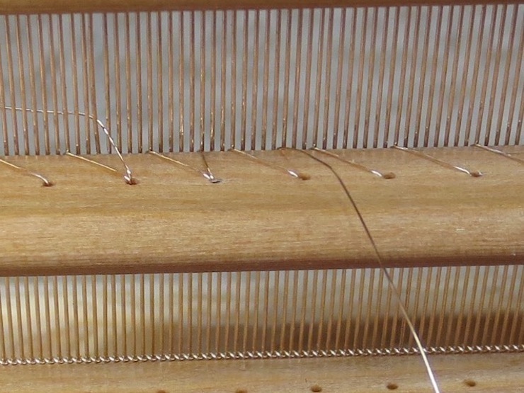
The stitches of a sewing wire are intentionally made much closer at the end of the rib. But since in this case a second wire will be added, the first wire needs only a couple of stitches before it is given a simple twist to secure the end. The second wire will take the normal amount of stitches and will cross over the first wire, binding it firmly in place.
The same pattern is followed at the other end of the rib.
This is how it looks with one sewing wire completed .
Now the second sewing wire is started on the same rib, passing through the same holes but adding new stitches about halfway between the ones made by the first wire.
When this second wire reaches the end of a rib the usual pattern of many closely spaced stitches is followed. In this photo the second wire still has a few more stitches to go before it is tied off.
Here the other end is being finished off, twisting around itself after the last stitch so it won’t slip back.
When the sewing is complete the stitches will average every four wires throughout the area where paper will actually be formed. Along the edges of this mould there is one stitch for each of the last eight laid wires. This is a little excessive; this was my first attempt at sewing with two wires and I hadn’t gotten the best pattern figured out. Only the last three or four stitches need to be placed this closely.
I haven’t made a large, very fine laid mould using this method yet but I would be inclined to try it. It may be worth taking the extra time and trouble to get close stitching without wearing out the sewing wire as much. And the shorter wires would be easier to sew.
This was to be a post about improvement. The laid wires were straighter and the facing much improved. Instead, in a few thoughtless seconds, scrap!
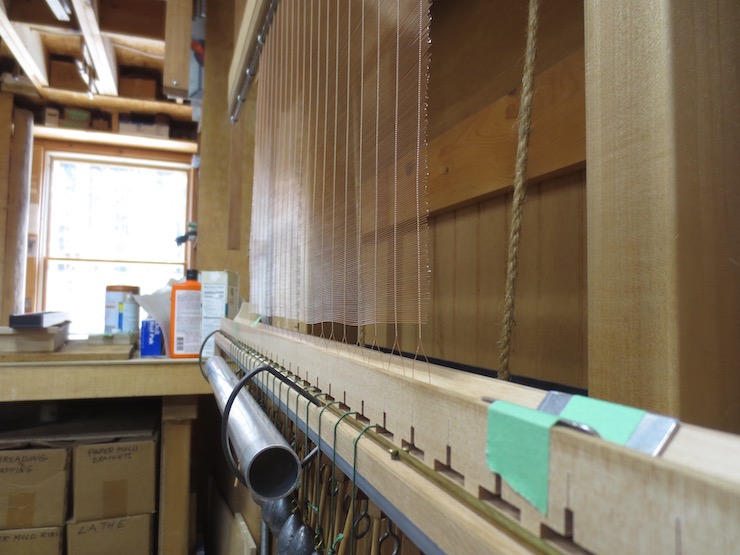
After the laid facing was completely finished I cranked too far and look what happened. The bottom of the wire twisting mechanism started to run into the wire slides and push them down. This stretched the chain wires and wrecked the facing. (I had noticed some resistance as the facing was being made and was trying to see what caused it by cranking some more. )
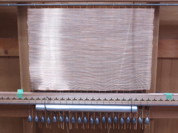
The facing started out very well. The laid wires pulled very straight after adding a new fixture to the wire straightener. See “An Addition” at the bottom of Post #19.
The wire worked beautifully. It was to be another 12″ x 18″ fine laid facing. It is a first attempt of 27 laid wires per inch using some new sizes of wire. Laid wires are .0158″ diameter and chain wire is .0106″.
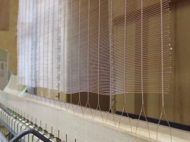
The chain wires stretched well up into the body of the facing.
You can see how the wire slides are being pushed down. The wire weights have already been removed. I pulled a few laid wires out after cutting the facing off the loom and found that they can be re-used to make a new facing to replace this one.
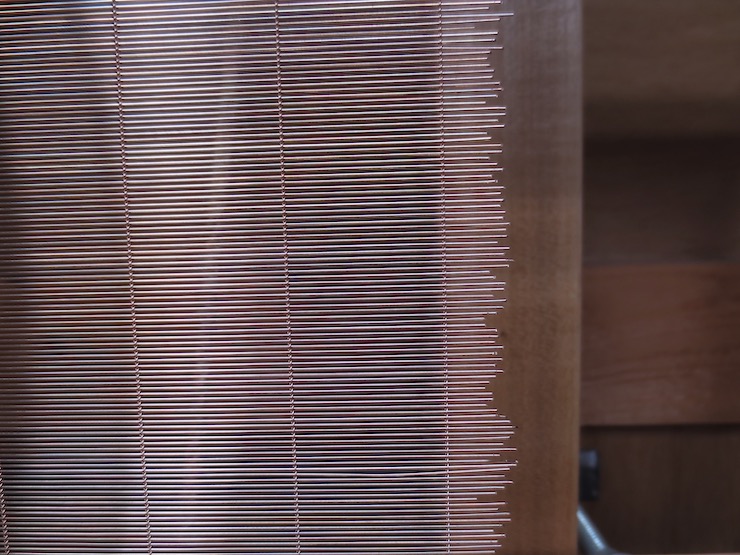
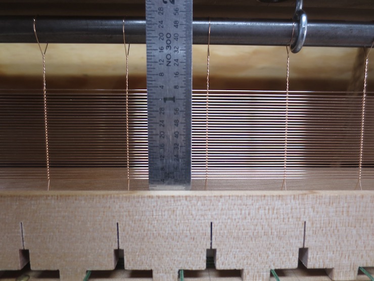
At 30 wires per inch this is the finest facing I’ve ever made. After running tests to see what size chain wire to use I set out to make a facing for a 12″ x 18″ mould. The laid wires are .0144″ diameter 3/4 hard phosphor bronze and the chain wire is .0102″ diameter annealed phosphor bronze.
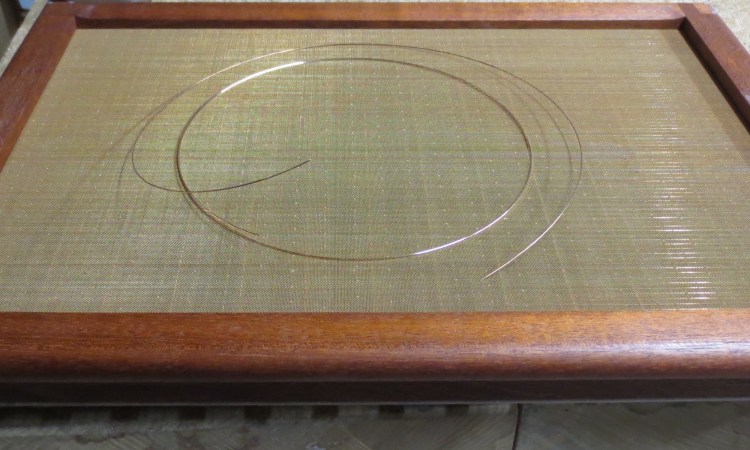
A customer expressed interest in this paper produced in Amalfi, Italy in the 1960s. It is ‘antique laid’ paper made on a single faced laid mould (as all European paper was before the mid 1700s). Note the distinctive ‘shadow zones’ along the chain lines created by uneven drainage from the mould structure. The paper shows a laid wire spacing of about 30 wires per inch. I am told that close wire spacing was typical of a lot of 17th century papers. In those times the wires would have been copper or brass. It’s not clear whether these wires would have been put together on a loom or by hand. It would have required a great deal of skill to make a laid facing like this by hand.
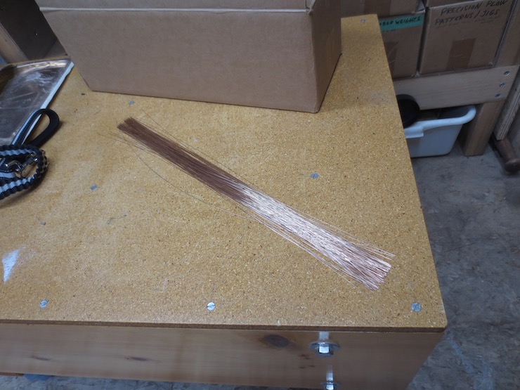
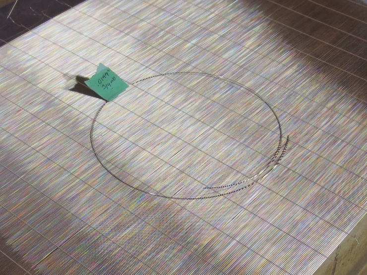
I welcomed the challenge of trying out a very fine facing on my loom! First the laid wire needed to be straightened (and this wire started out very curved). Here is a loop of the new wire placed on the finished facing. The wire came with a very tight cast of about 5-1/2″ diameter.
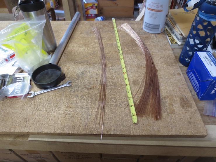
At first it was difficult to straighten it well. It’s never perfectly straight. Most of the wire ended up like the larger pile on the right. Very near the end I had a breakthrough of sorts that allowed me to pull wires that looked like those on the left.
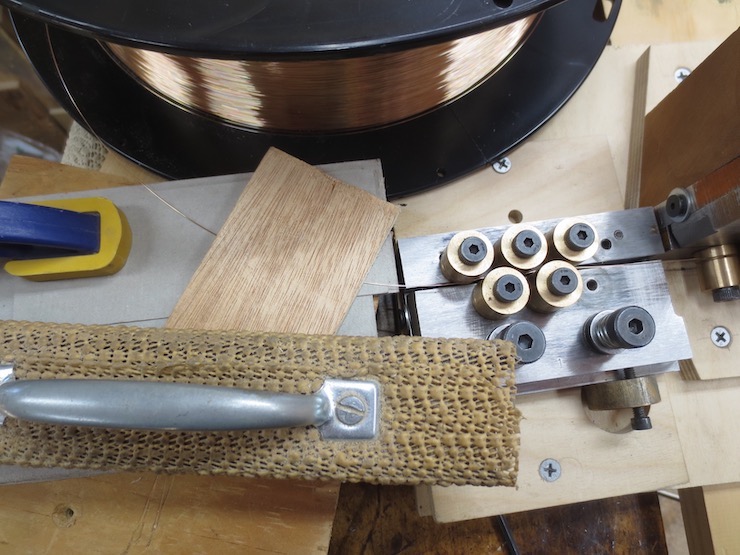
What helped was drawing the wire between pads to control the orientation of the wire as it entered the first set of rollers, thereby improving consistency in the final, straightened wire. Small adjustments to the rollers (to take out either cast or helix) now seemed to give understandable and more predictable results. Before this the wires would cycle back and forth from nearly straight to fairly curved making it difficult to determine what adjustments to make. The pads were built up (from scraps around the shop) to hold the wire at the same level as the grooves in the rollers. In this first, somewhat random attempt, the layer just below the wire is cardboard and a small piece of plywood is held on top with a weight. Layers of paper shim (these are hidden under the weight) are used to create a space for the wire to travel through without much drag. The purpose is to hold the curve (cast) of the wire firmly horizontal as it enters the grooves in the first (horizontal) bank of rollers. Next time I’ll make a more permanent version to bring the pad even closer to the first roller. I’m pretty sure this will help and look forward to trying it out next time.
I have now added a permanent version which can be viewed at the bottom of post #19, “Straightening Laid Wires”.
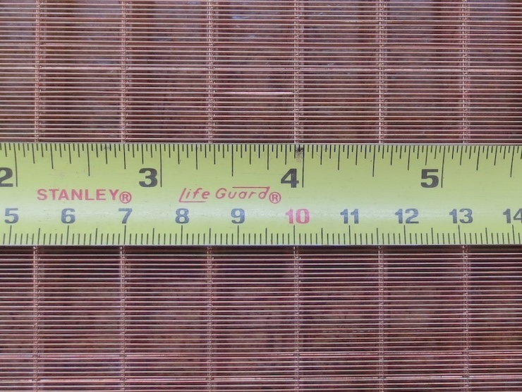
Counting 10 clicks using this 23 pin ‘counting wheel’ yields an interval of 29.9 wires per inch. After the wire weights were removed from the finished facing it shrank just a bit and ended up even closer to 30 wires per inch.
The two sizes of wire worked beautifully together though the curvy wires were a little difficult to feed into the trough.
The excessive curve left the ends a bit wild. After being stitched to the mould the usual process of smoothing out wires along the ends will be more difficult.
The partly finished laid facing.
Many old papers were made on moulds with closely spaced, very fine laid wires. This facing will be made into an ‘antique laid’ (single faced laid) mould. In the hands of a skilled papermaker this should allow some of the qualities of these old papers to be reproduced.
I’ve long been intrigued with the challenge of making bookbinding ploughs. A problem has been finding a source of knives. (Please let me know if you have any suggestions). The knife used in this post is high quality but it is small and not suitable for trimming thick books. This post details a method of using this knife in a different way to overcome this limitation.
These ploughs were designed to be adapted to fit different presses and knives by screwing appropriate blocks to the bottom. For this experiment I shaped and added red oak blocks to try out a different way of mounting the knife. The knife is fastened to the bottom of a beam. This allows it to traverse a long way without being limited by the length of the knife.
I used a spare guide bar for the beam from an earlier version that I no longer use. (Two of the newer version are installed on this plough.)
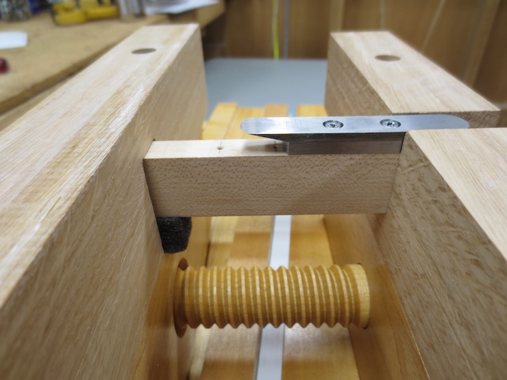
One end of the beam is screwed firmly into a slot at the bottom of the handle side of the plough. A row of holes allows the knife to be positioned at various places along the beam for trimming various thicknesses. A small piece of tape has been placed on one end of this steel spacer block. When the screws are tightened down this springs the knife; pushing the tip out so that only the cutting edge will contact the paper being trimmed.
The spacer block sandwiched between the knife and beam adds cutting depth. The knife is 1/8″ thick and the block 3/16″ thus limiting the depth of cut to 5/16″.
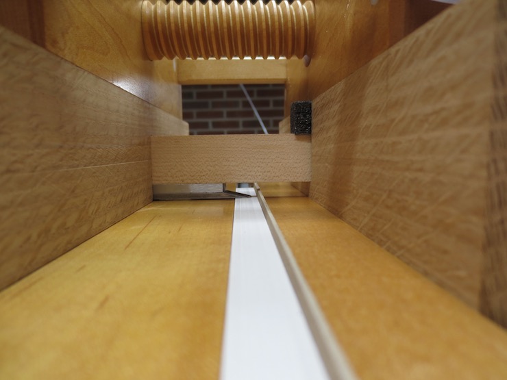
A view from the far end – opposite from where one would normally stand. The handle side of the plough is on the left. The knife is elevated about 1mm above the surface of the press. The bottom surface of the knife never touches the press.
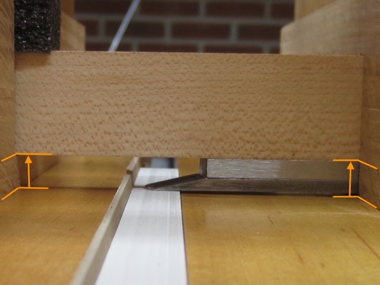
I have flipped the same photo and zoomed in to show how things would look from the operator’s point of view. The plough is constructed to hold the bottom of the beam exactly the same distance above the press at both ends (orange lines and arrows). This means that the plane of trim is established by the upper surfaces of both halves of the press. The knife is equally supported at all phases of its cut. The piece of black plastic foam at top left presses the sliding end of the beam against the bottom of the groove that it slides in. Next time I will use a steel bar instead of a wooden beam. The weight of the bar alone should eliminate the need for this packing. The holes for attaching the knife would be tapped to receive machine screws. The relatively small knife would be united with a hefty piece of steel to add rigidity.
Here the knife is screwed down in its shortest position.
If screwed down here the plough could theoretically trim 3-1/2″ of width even though the knife is short. However the cut is also limited by the width of the jaws of the press and the design of the plough. The screw of this plough isn’t long enough and the press isn’t wide enough to trim more than 2-3/4″.
Different sizes and shapes of knife could be substituted as long as they have countersunk holes for attachment to the beam. A circular plough knife could likely be made to work as could various sizes of rectangular bar-shaped knives.
This end of the knife beam is rigidly attached to the handle side of the plough. The handle side of the plow body along with the beam form a rigid T shape so the knife can’t tip sideways as it slices.
The other end of the beam rests on the bottom of a wide notch to hold it a precise distance above the press. This keeps the cutting edge traversing in a plane exactly level with the top surfaces of the press as the knife is advanced by turning the wooden screw.
A view from the operator’s end.
This was an experiment to see if this would work and I think it worked very well. Along with a steel beam, version #2 likely won’t be as tall and may have longer screw and guide bars.