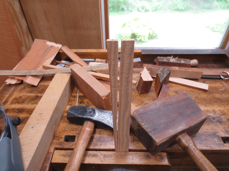
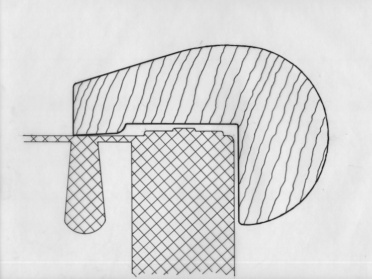
The wood that has been seasoned for making ribs now needs to be straightened and shaped to a distinctive tear drop shape. This is narrow at the top so as not to obstruct the flow of water while forming sheets yet wide enough at the bottom to form pegs at the ends. These rest in holes to connect the ribs to the frame. Later posts will discuss shaping pegs, drilling for the stays and sewing, and otherwise finishing the ribs.

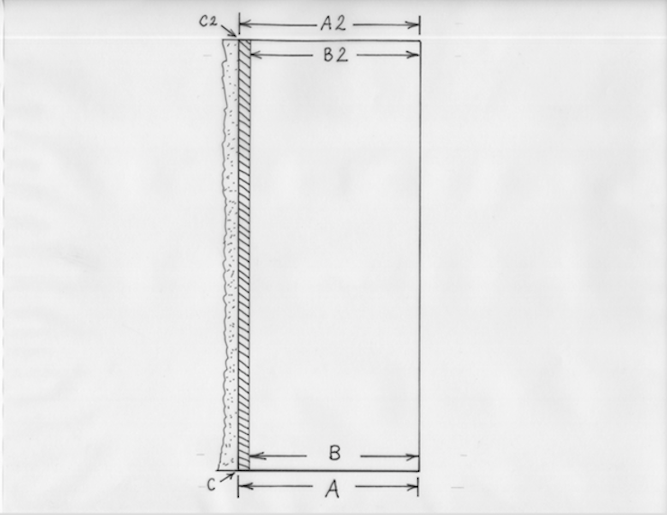
This drawing was made to calculate and keep track of the angles and dimensions of two sizes of ribs. The ribs that are being made in the following photos are the smaller size; 5/8″ deep with 3/16″ diameter pegs centered 1/2″ from the top. Single faced laid moulds have ribs that are 1/16″ wide at the top. Double faced laid and wove moulds use ribs with 3/32″ wide top edges. The width at the bottom is not critical but the ribs need to be thick enough there to form the pegs that fit into holes in the mould frame. In addition to the sizes above I have used ribs that are 15/16″ deep for large moulds and even 1-1/8″ deep for very large moulds. And I have used 1/2″ deep ribs for very small moulds.

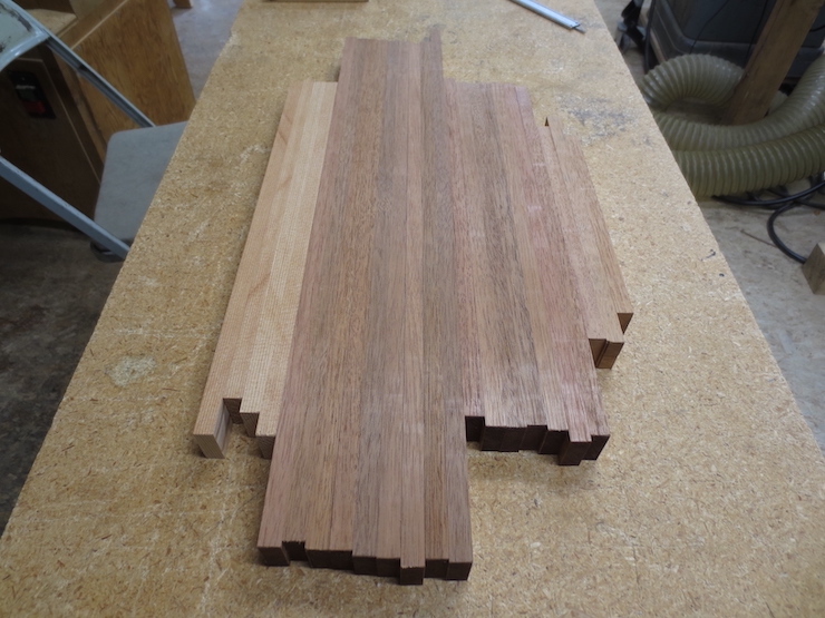
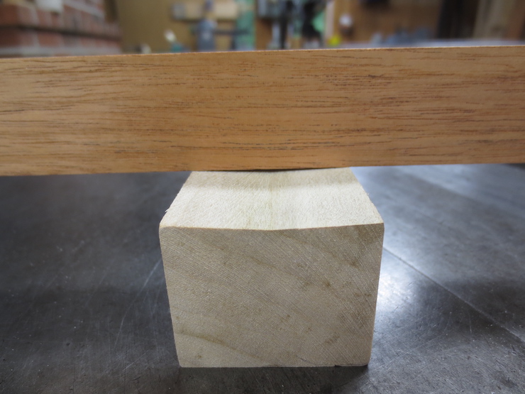
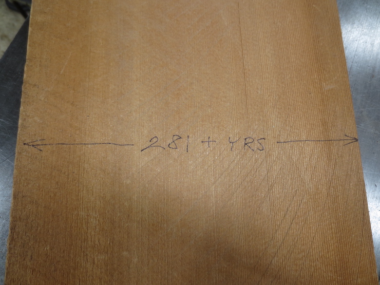
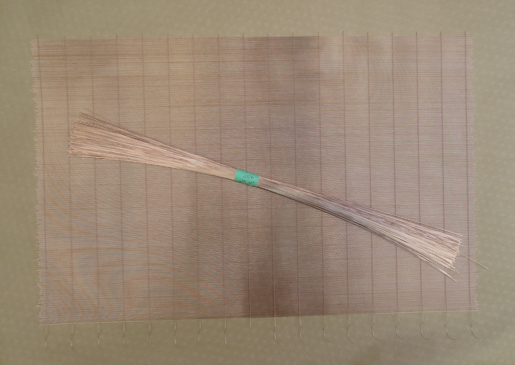
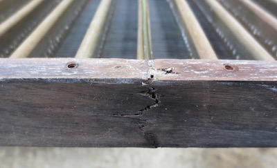
The rough stock which has been previously seasoned. (See previous post)
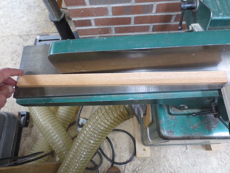
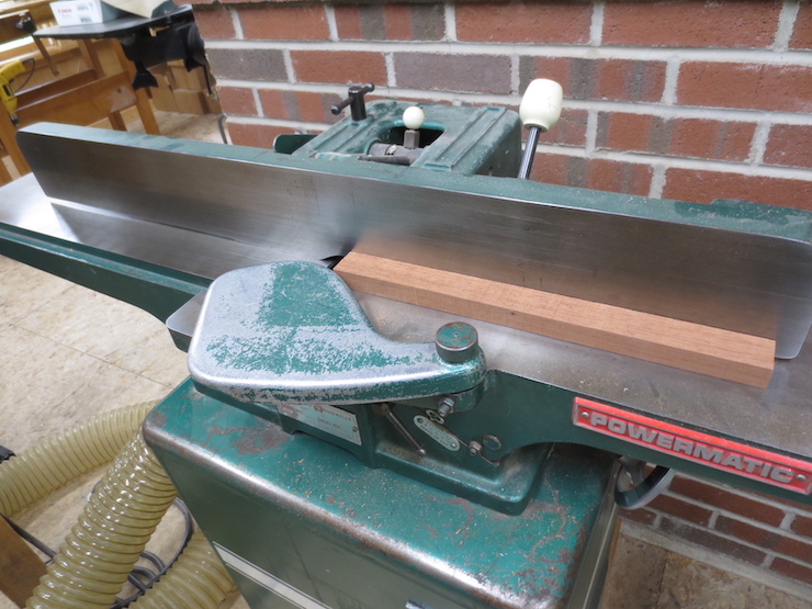
One side of each rib is flattened on the jointer.
Then the top edge is also made flat and straight, at 90 degrees to the side.
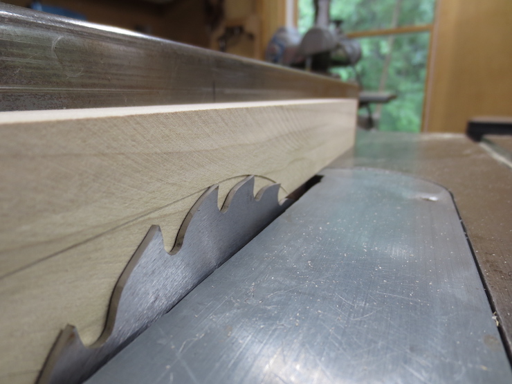
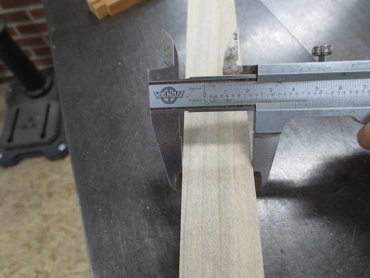
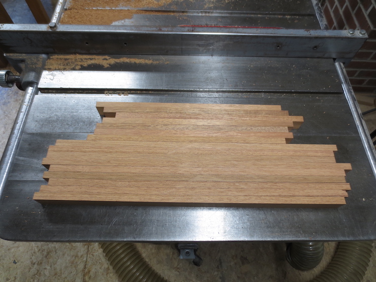
The ribs are sawn slightly oversized at the proper angle. The angle depends on the size and type of mould. For these moulds the angle is 7 degrees off of perpendicular. (Since the wide sides will form an angle of 14 degrees subtract half of that from 90 degrees) This makes a slightly acute angle of 83 degrees.
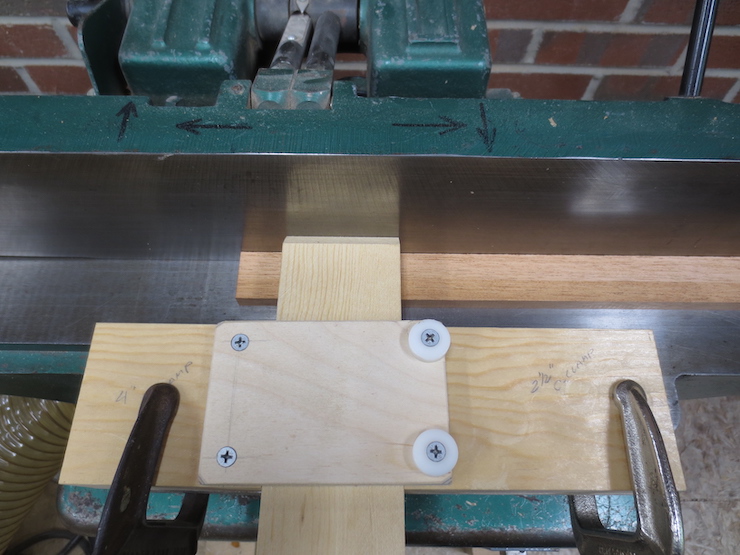
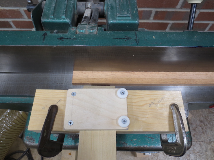
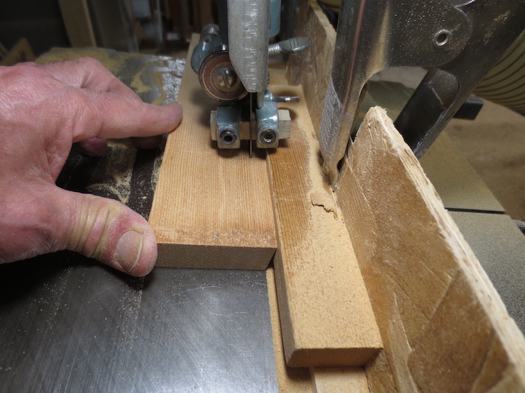
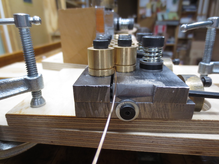
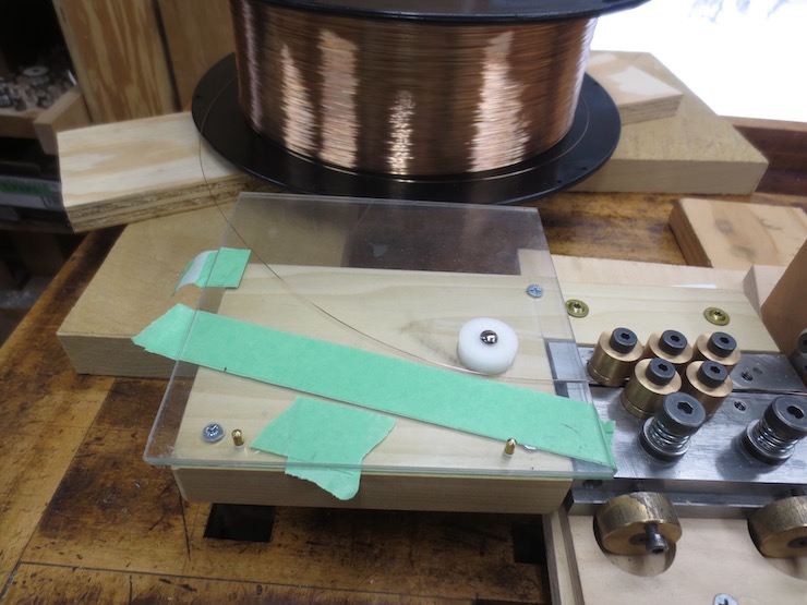
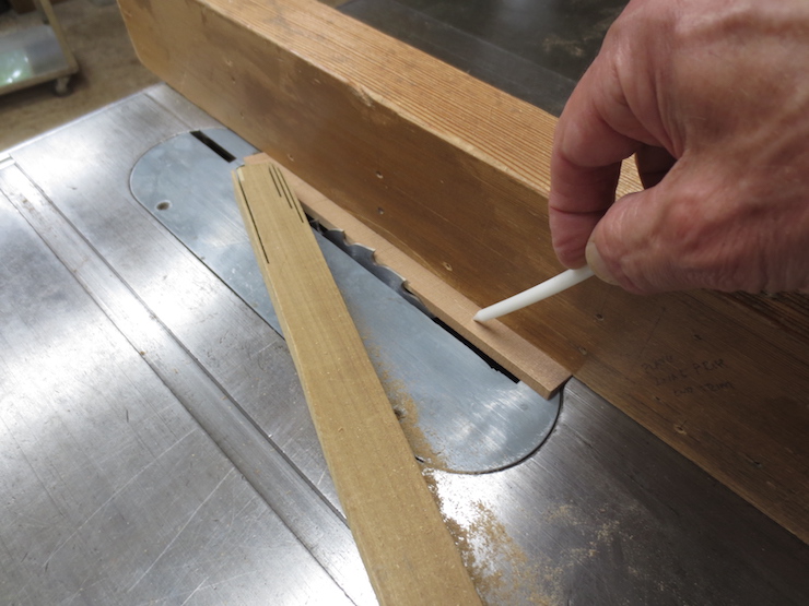
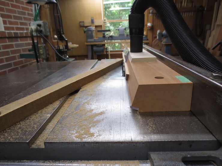
Then the rough side of each rib is sawn to the correct angle on this suction fixture. Here the saw is set to create an angle of 14 degrees but leaving the rib a bit thick for one more trim.
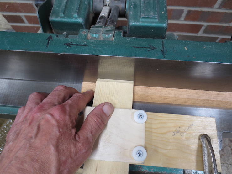
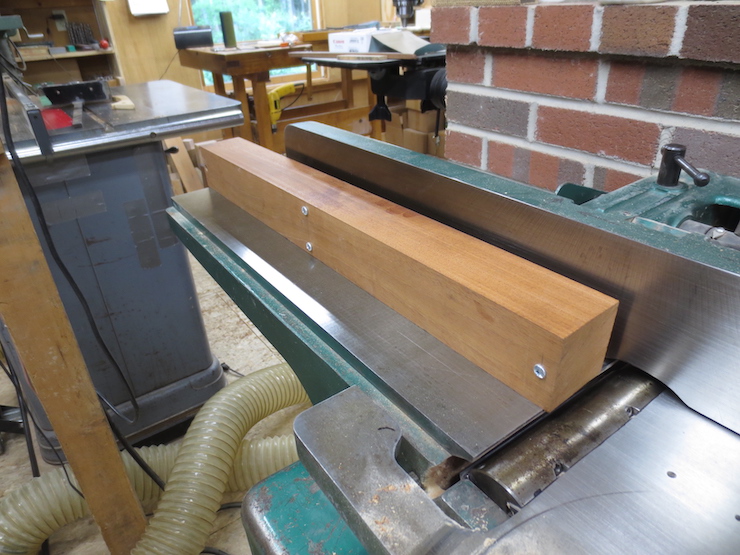
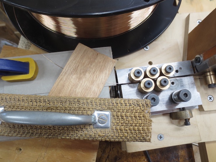
This shows how the ribs are held to the special attachment with suction supplied by a shop vac as they are fed past the rip saw blade.

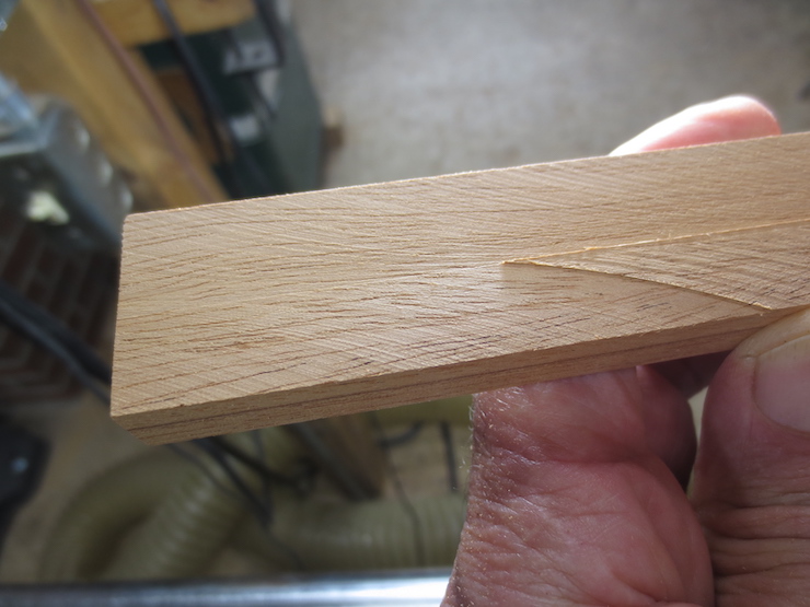
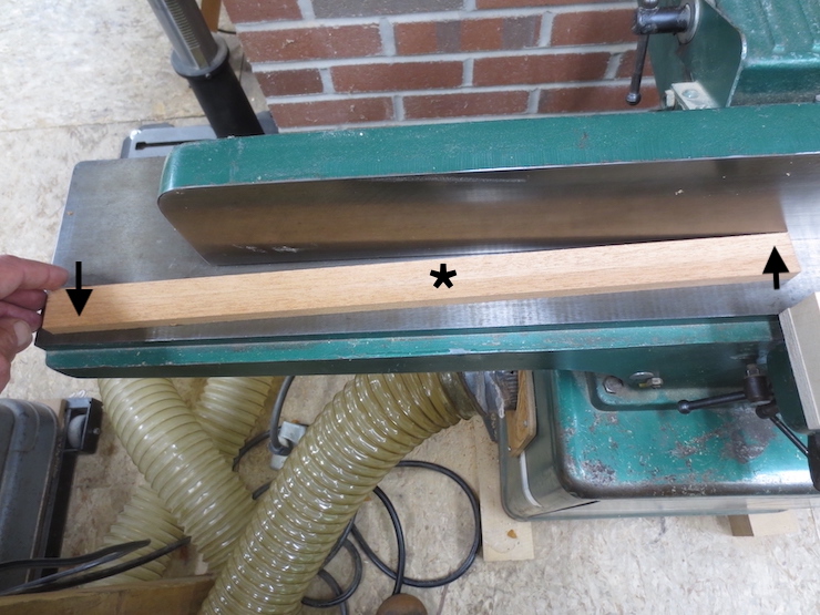
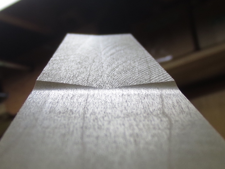
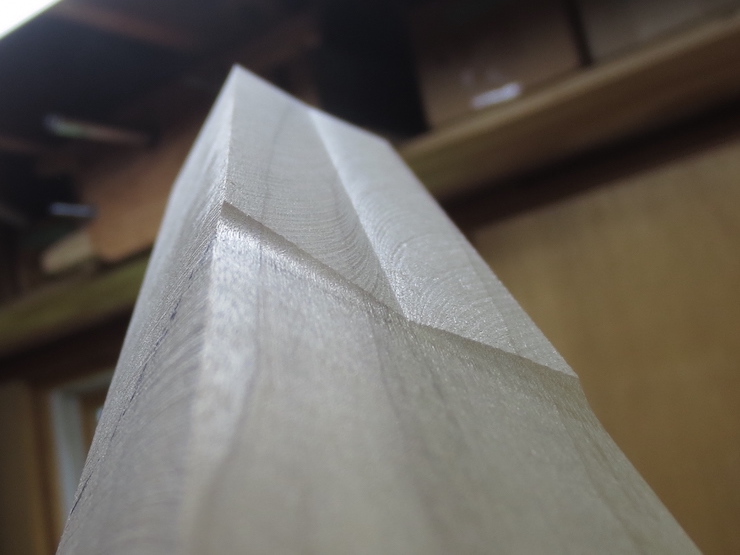
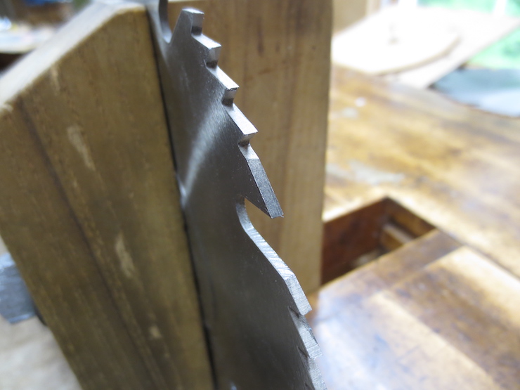
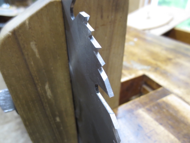
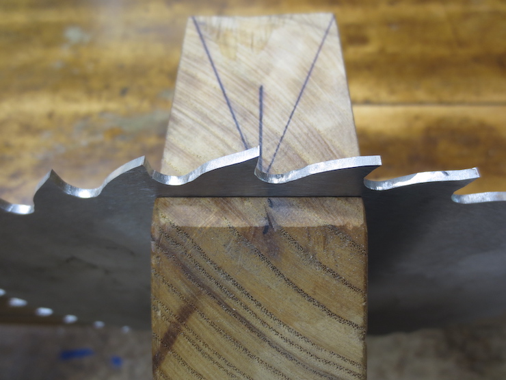
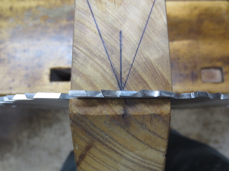
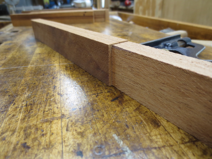
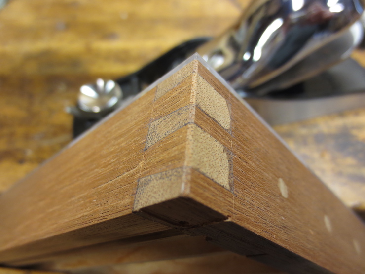
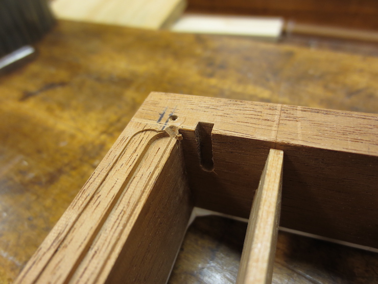
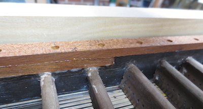
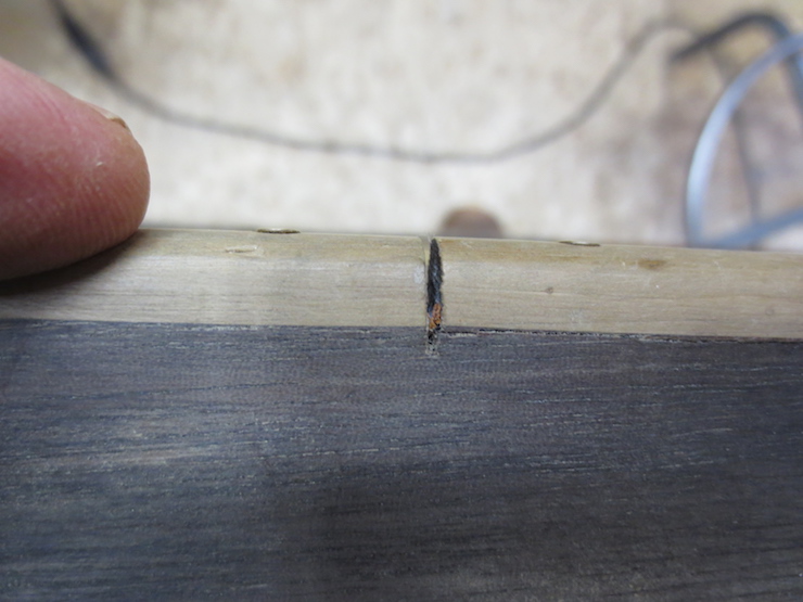
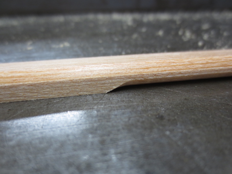
The rib on the right has been jointed, straightened and had its bottom sawn to 83 degrees. The arrow points to the juncture of the two jointed sides; this angle is now 90 degrees. This corresponds to step 2 in the photo below.
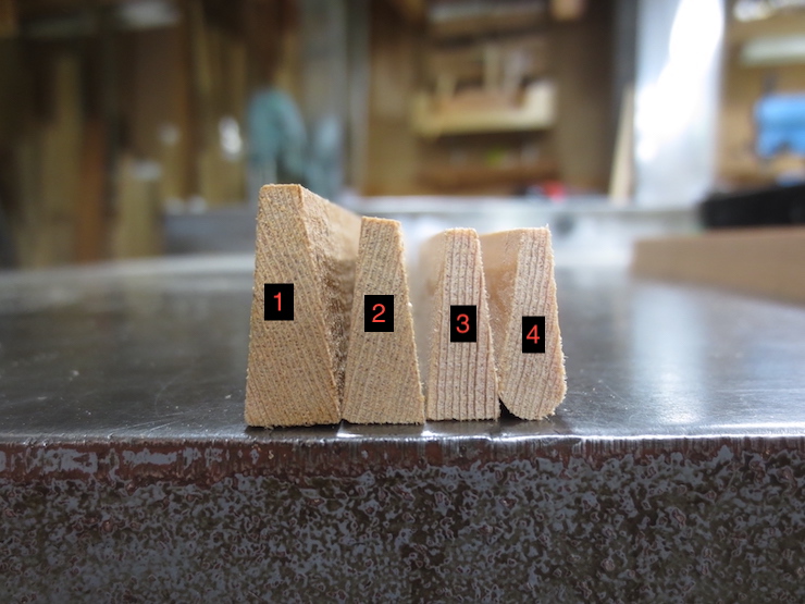
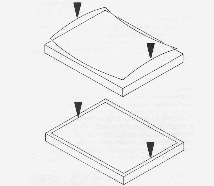
Stage 1 is the rough stock. Stage 2 has the left and top faces jointed and the other two faces sawn to the correct angles. (So far in this post stages 1 and 2 have been completed.) In stage 3 the stock will be straightened once again and reduced a little more, but with the 90 degree angle on top corrected to 97 degrees. ( So that when the ribs are installed in the mould their top surfaces will lie in a plane parallel with the top of the mould). Step 4 shows the finished stock. The reason for reducing the dimensions of the ribs in two steps is to make them straighter. They will distort slightly each time material is removed; this way they are likely to distort less the second (last) time.
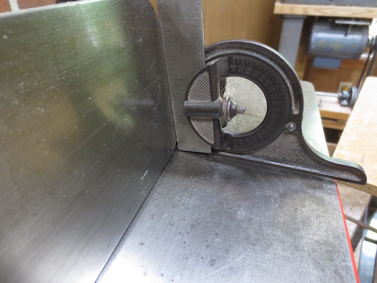
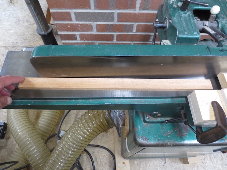
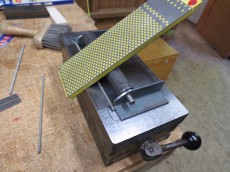
The wide face of each rib is once again flattened and the top edge jointed, but not at 90 degrees this time. This shows the jointer fence being set to 97 degrees to joint the tops of the ribs.
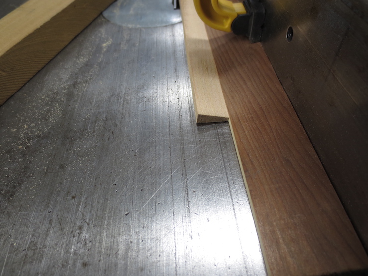
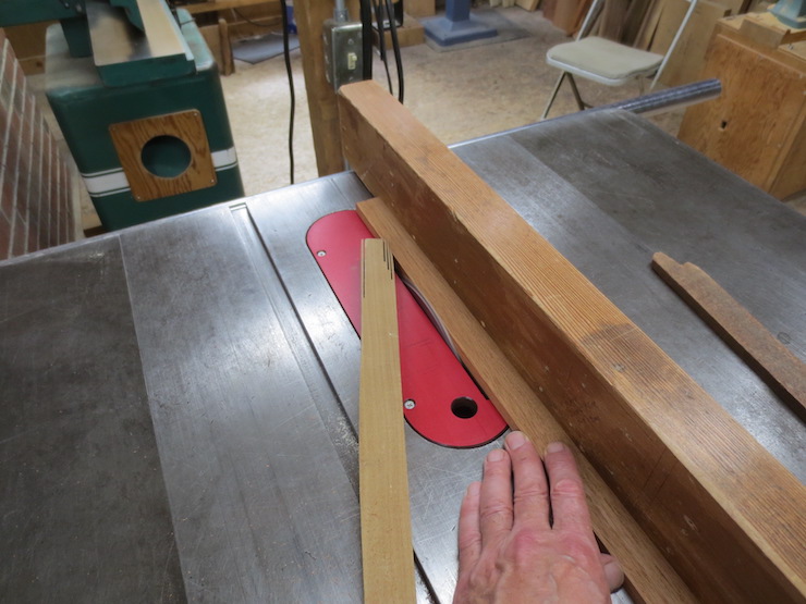
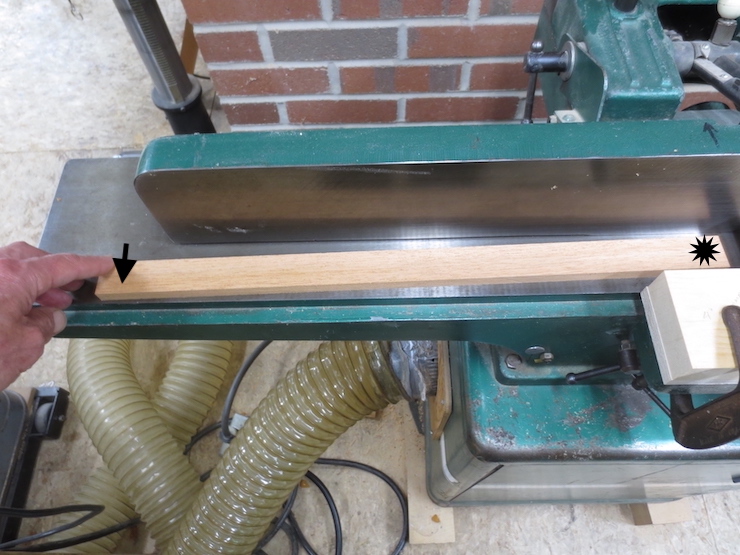
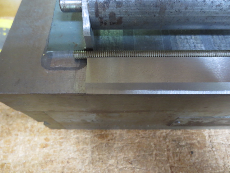
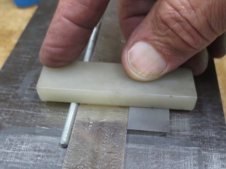
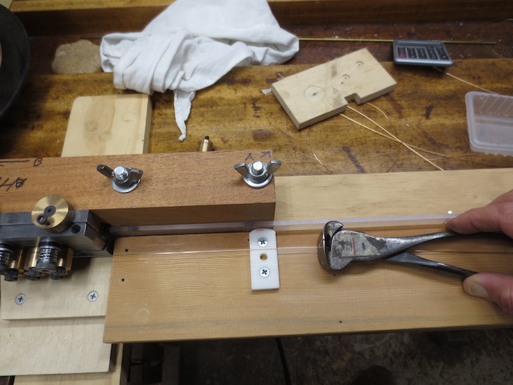
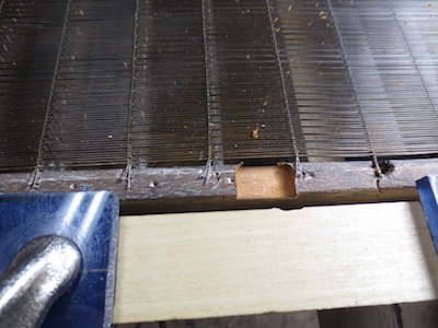
The ribs are now trimmed to their final depth. It is best for the fence to have an angled edge to match the top angle of the rib. This is easily done by setting the angle for the rib bottom on the saw and feeding a thin strip of wood through. This is then clamped in place as a temporary fence to saw the wood accurately to width.

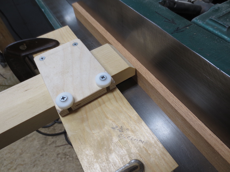
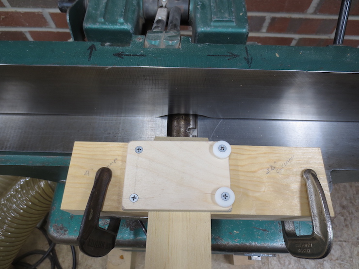
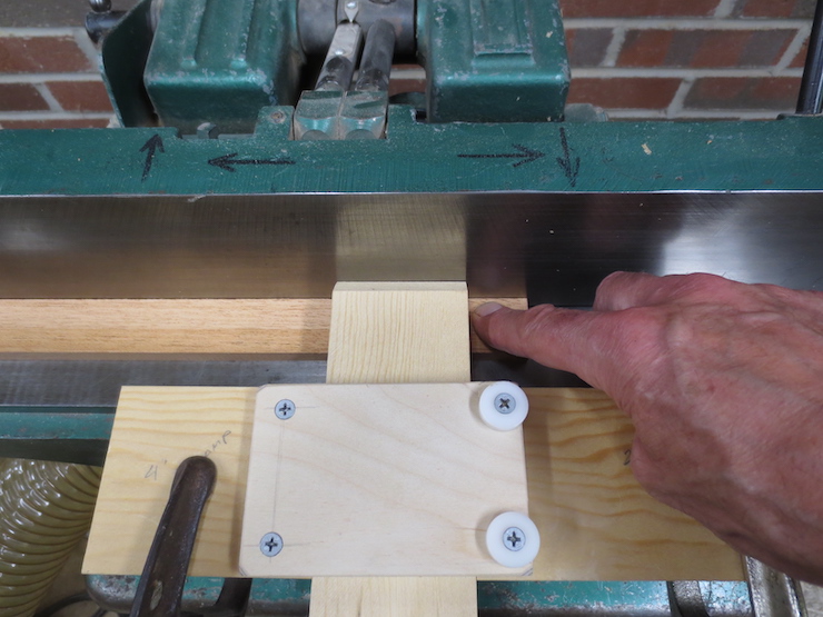
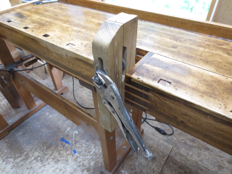
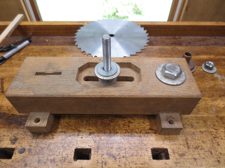
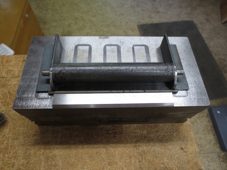
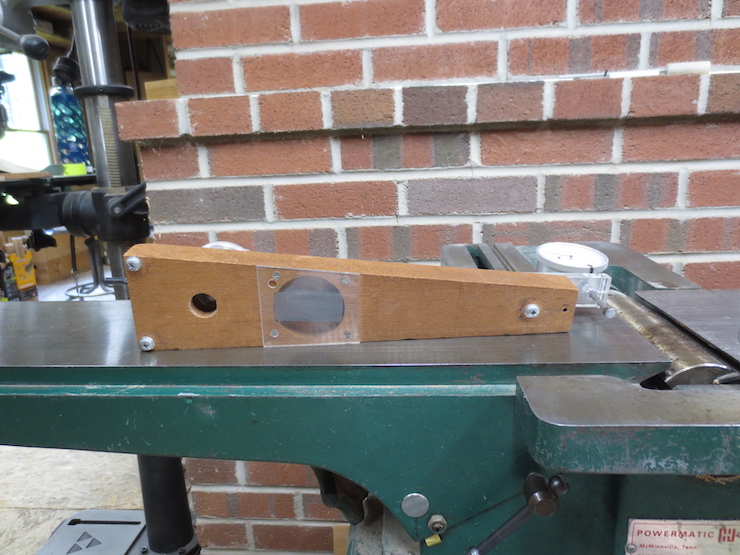
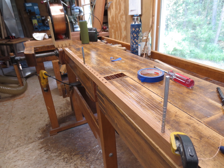
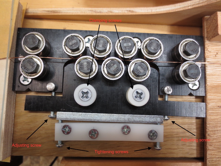
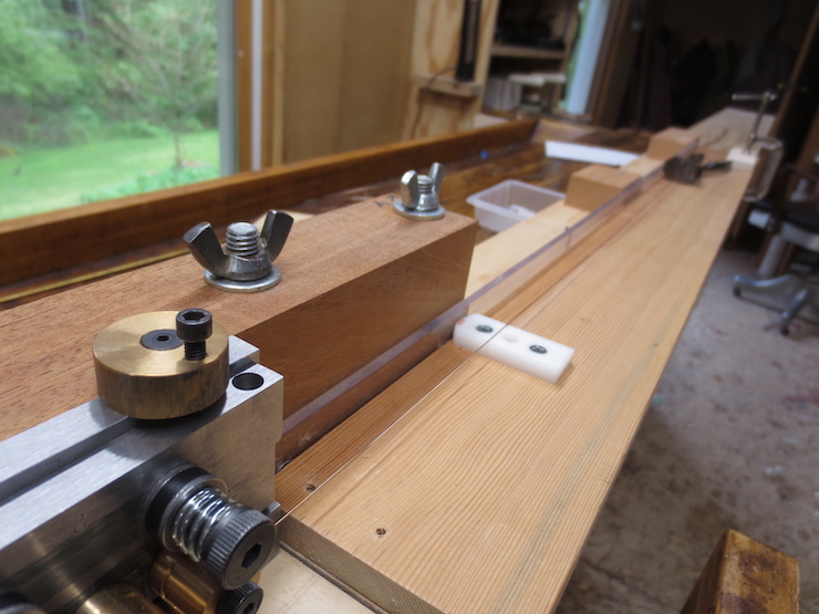
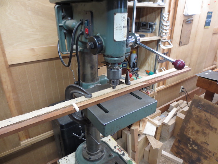
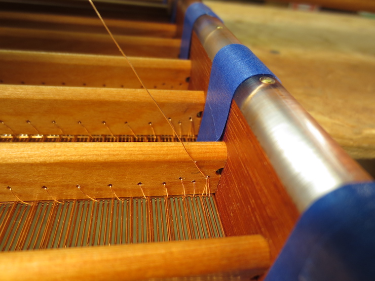
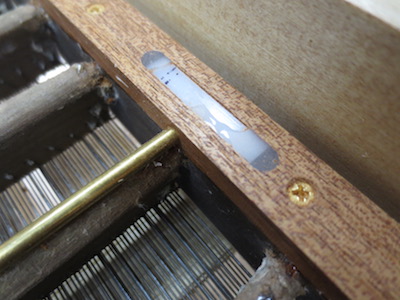
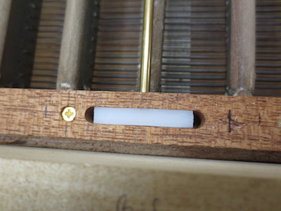
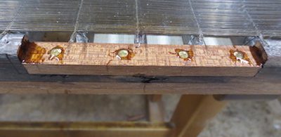
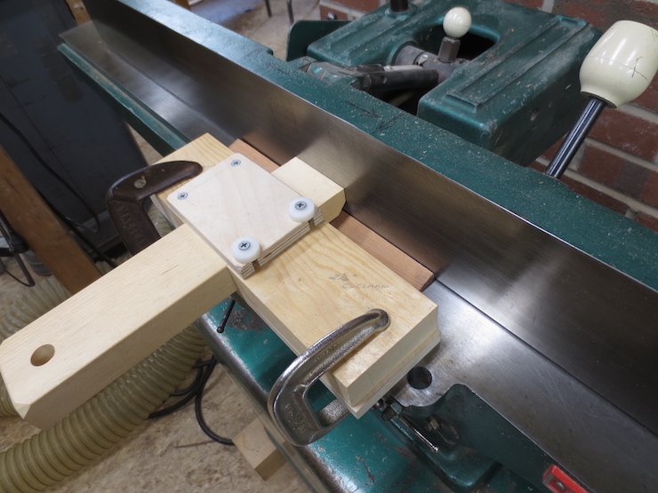
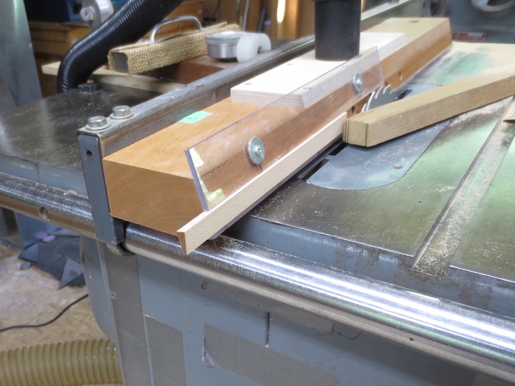
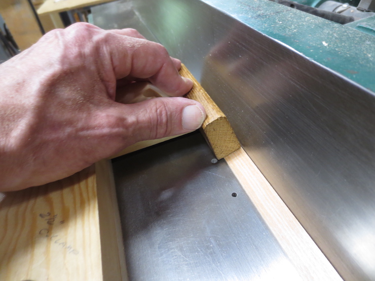
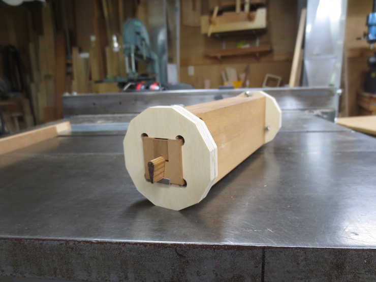
The ribs are ready for the second and last run through the vacuum fence. At the upper right you can see the 5 suction holes that hold the rib against the fence. The clear plastic piece at the top can be adjusted to help hold the ribs in place. The vacuum hose plugs into the large hole on top.
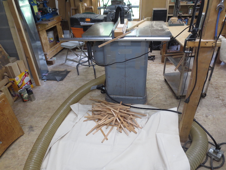
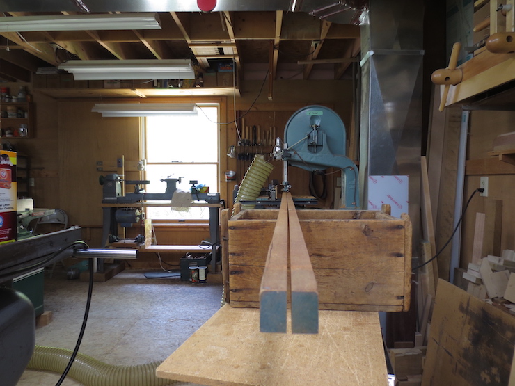
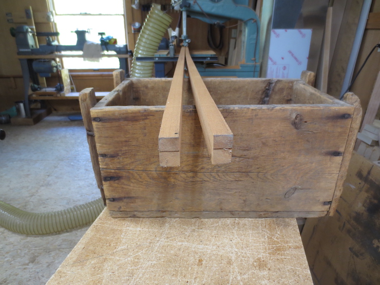
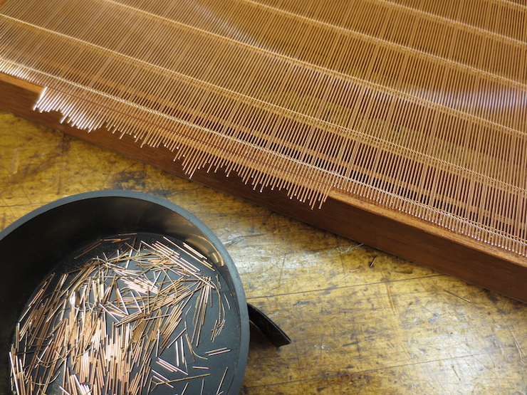
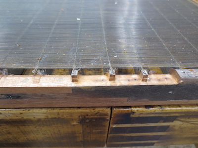
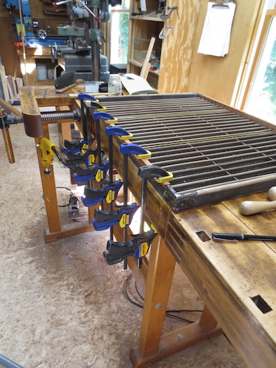
The ribs are pushed through one after another, each pushing the previous one, and they fall off onto the floor.
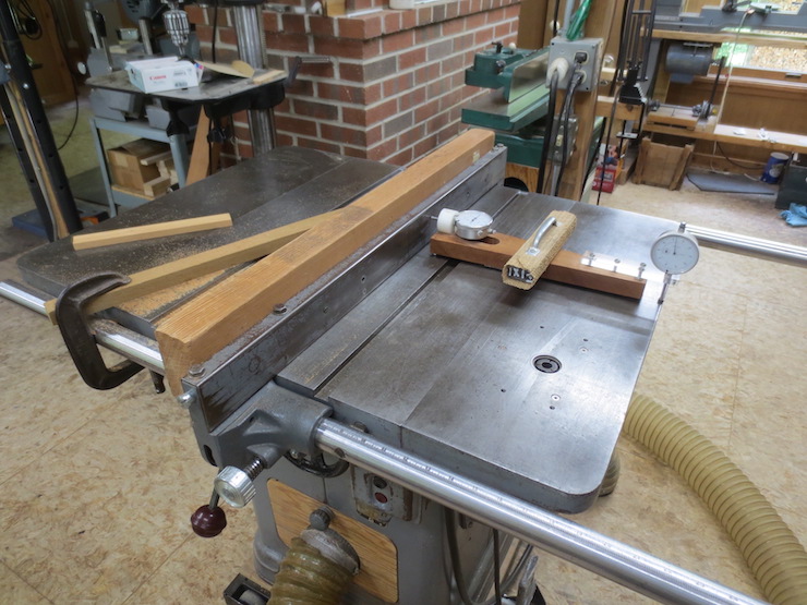
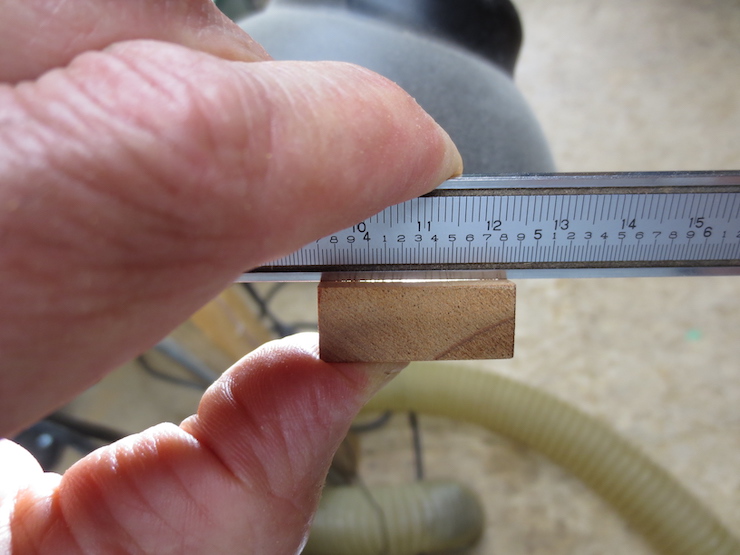
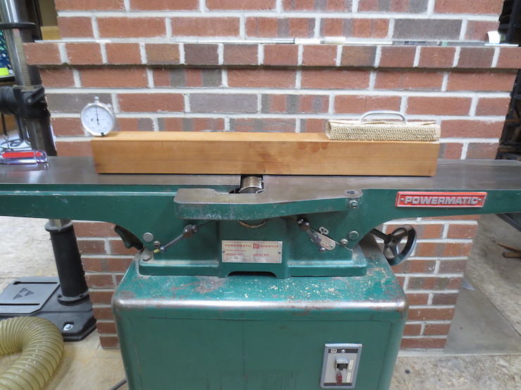
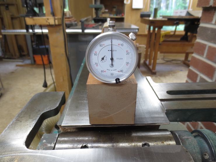
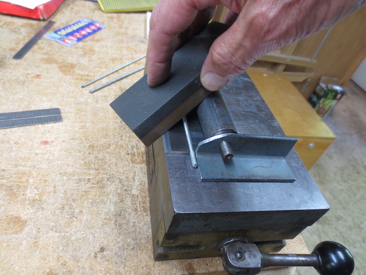
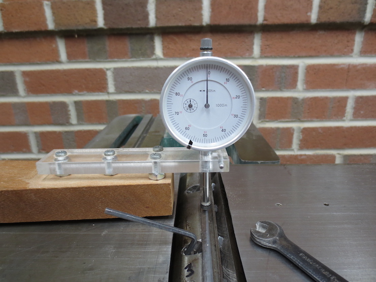
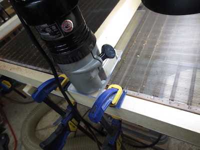
The rough side of each rib is now planed smooth. A block of wood spans the cutter head and presses the rib down against the in-feed and out-feed tables. First the rib is pushed and then pulled to keep the right hand at a safe distance. The same method of adjusting the tablesaw fence is used here as was previously used in thicknessing the mould frame. First a test piece is sawn on the vacuum fixture and planed smooth. Then it is measured to see how much more needs to be removed to end up at the right thickness. The fence is adjusted by that amount using the dial indicator.
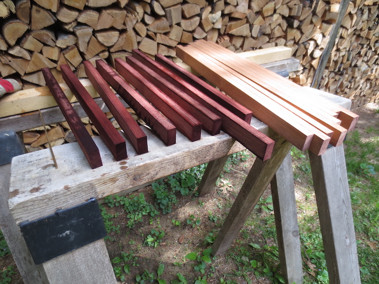
The bottom edges are rounded using a rounding router bit and an angled fence. A narrow band of the rough (but accurate) surface is left. After the ribs are complete and ready to install in the mould frame this will mostly sand off with a few swipes of a sanding sponge.
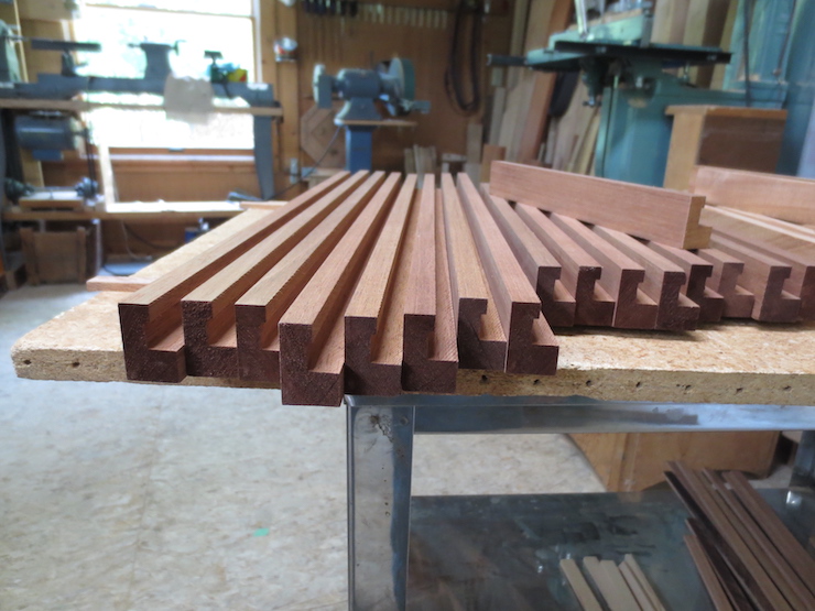
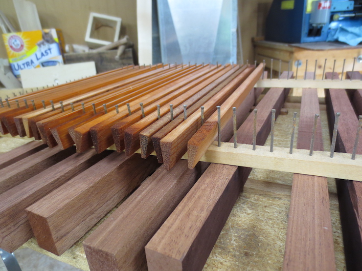
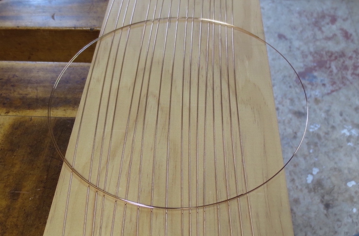
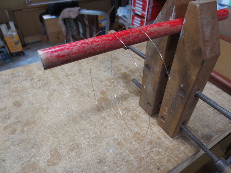
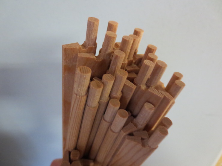
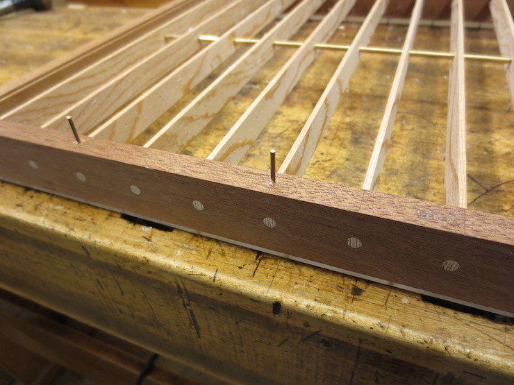
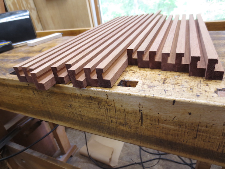
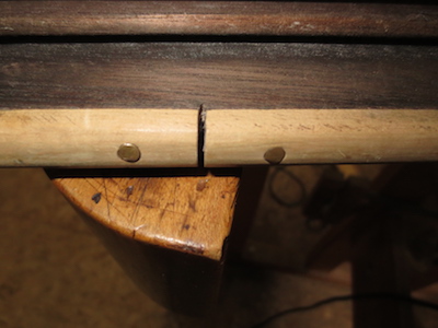
If the rib stock was correctly made the pieces will slide easily into this jig which will be used later to shape dowel-shaped pegs on the ends.

This 5/32″ radius round over bit was used to shape the bottoms of these ribs.

Angled edges on the fence allow the rib to be rounded in one pass each side.
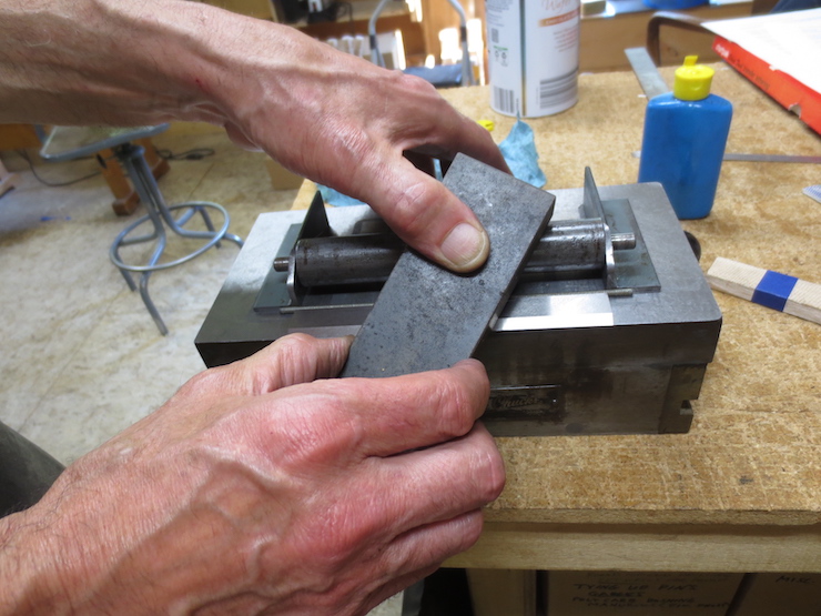
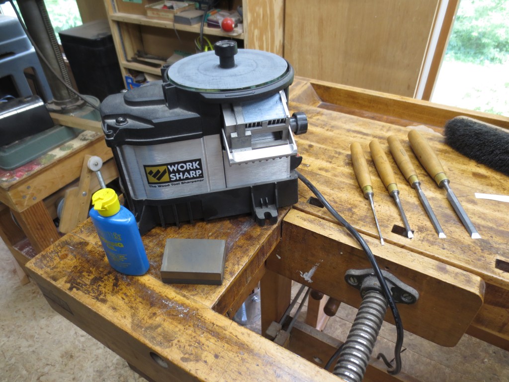
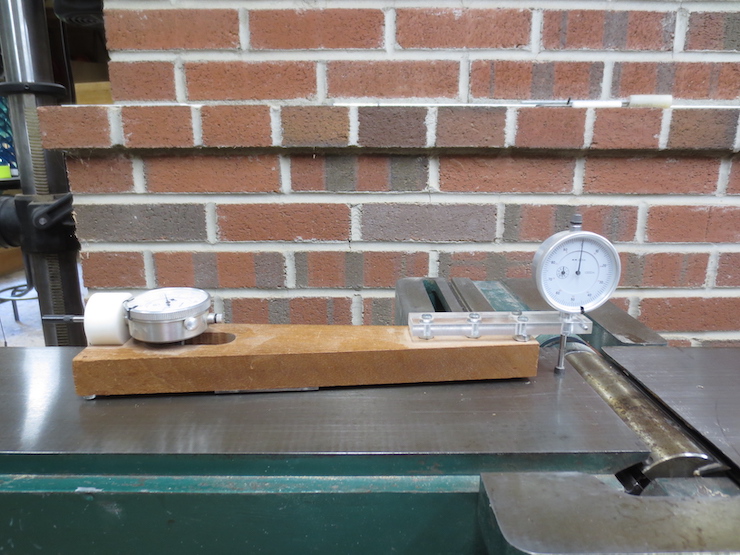
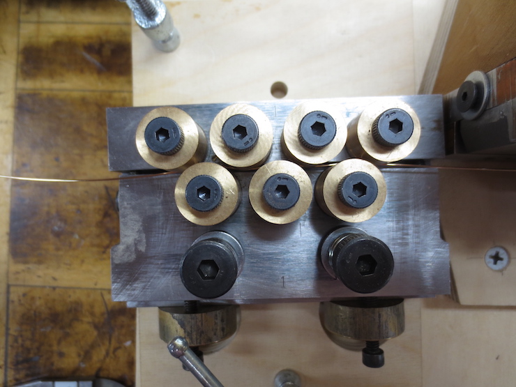
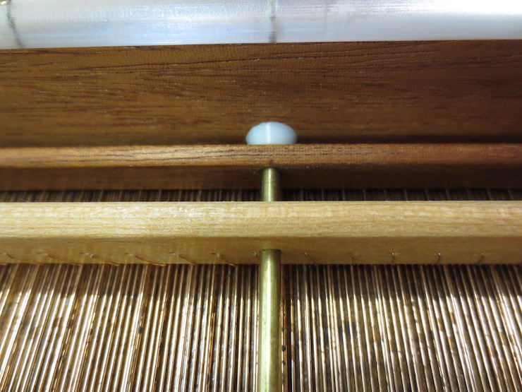
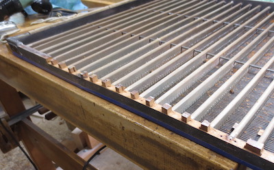
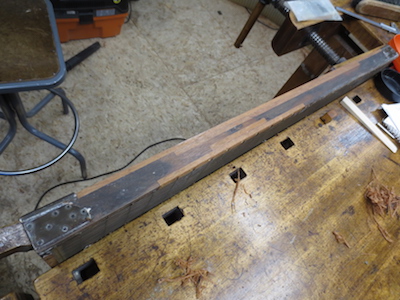
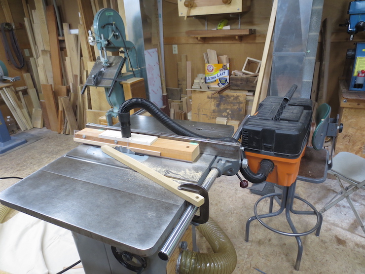
Another view of the vacuum/suction fixture. The saw blade can be tilted in the saw to prepare ribs of different angles.
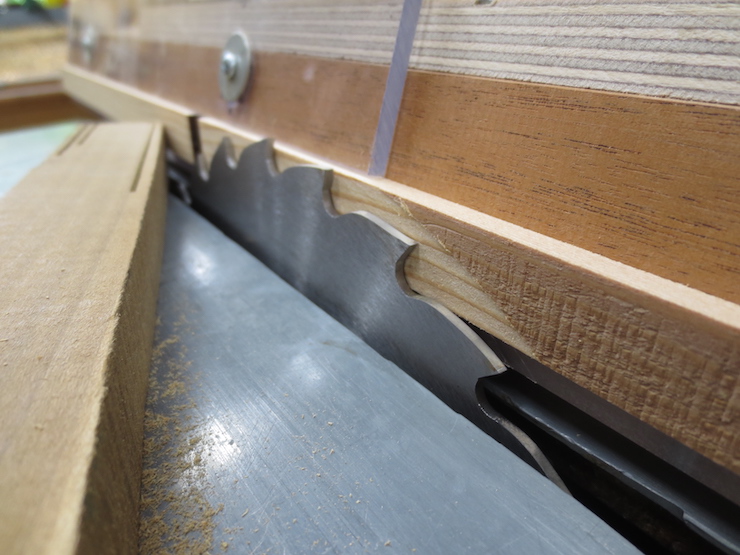
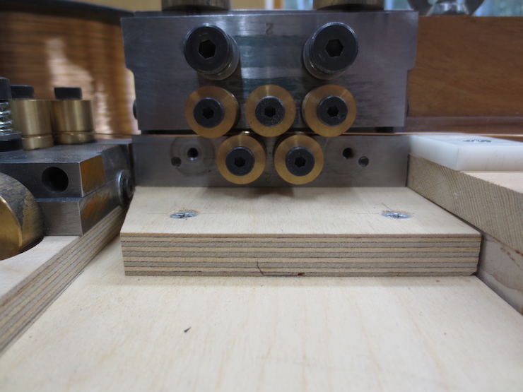
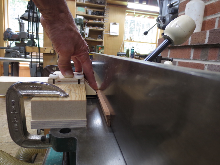
The rib is sucked tightly against the angled fence while being pushed through.