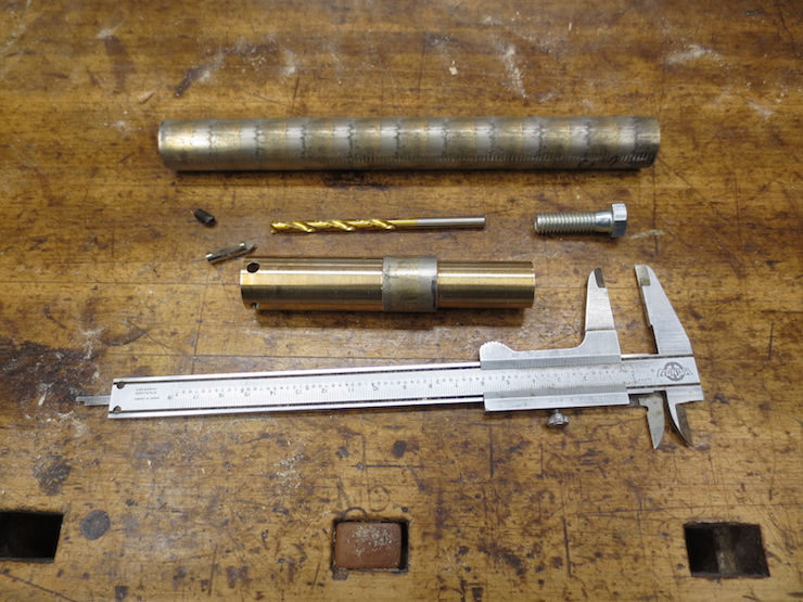
A previously finished 7/8″ 5 TPI bottoming tap (center) surrounded by tools and parts that will be used to make a standard ‘through hole’ tap having the same thread configuration. Both taps are made from the same 12″ rod of bearing bronze. The rough blank for the new tap is at the top.

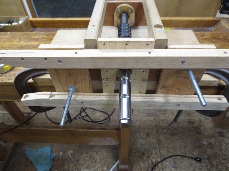
Here is the finished tap installed in the tap frame. The tap body is made of bronze and is a fairly simple tool being basically a shaft that includes an adjustable cutter. It is rigidly connected to a master thread which controls the path of the cutter as the tap is turned to create a spiral groove inside a hole. The master screw is visible at the right as is the coupling (black) that connects the tap to the master screw.
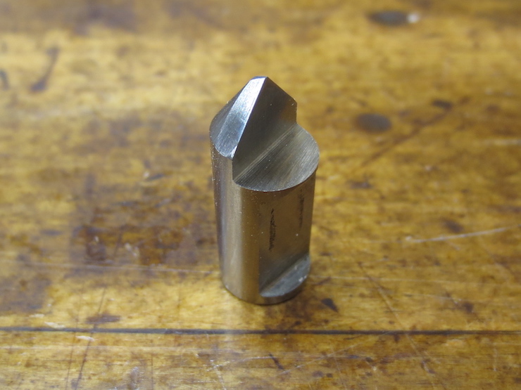
This is a tap cutter for a different tap. It is made from a short length of High Speed Steel drill rod. Note the recessed area where a set screw will press. It is ground at an angle to orient the cutting face at the proper cutting angle

This more clearly shows how a tap cutter is set on a slant to match the pitch of the thread being cut. This tap is made of a piece of ground steel shaft 1″ in diameter by 12″ long. It matches exactly the diameter of the master screws and shaft couplings and needed little modification. Making the smaller tap (7/8″ diameter) necessitated the switch to bronze in order to more easily machine it to fit standard size shaft couplings and master screws.
Making the 7/8″ 5 TPI Tap

One end of the bronze blank is faced and then drilled to receive the conical lathe center.
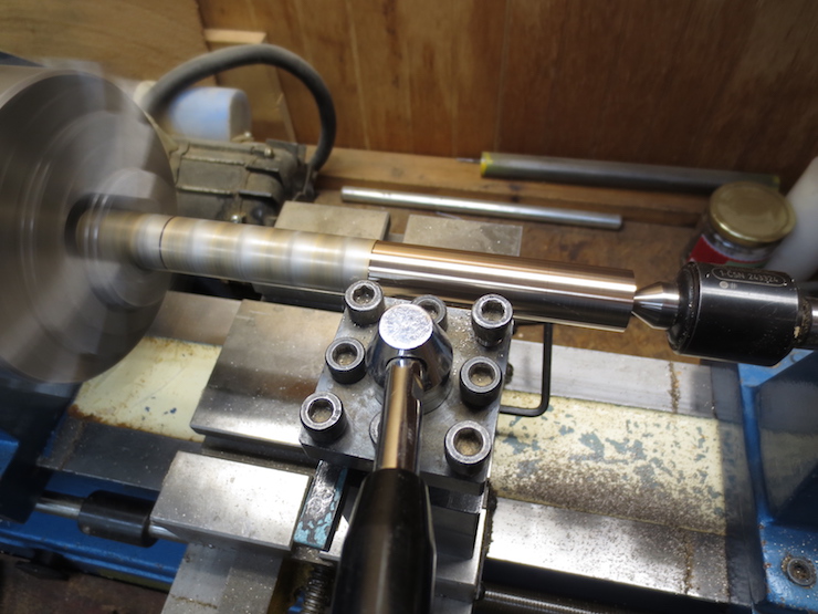
The bronze rod is manufactured and sold oversized so that it can be turned to a 7/8″ finished diameter. This was done in several passes using the lathe’s lead screw and automatic feed. The original mill surface remains at the left on this first pass.
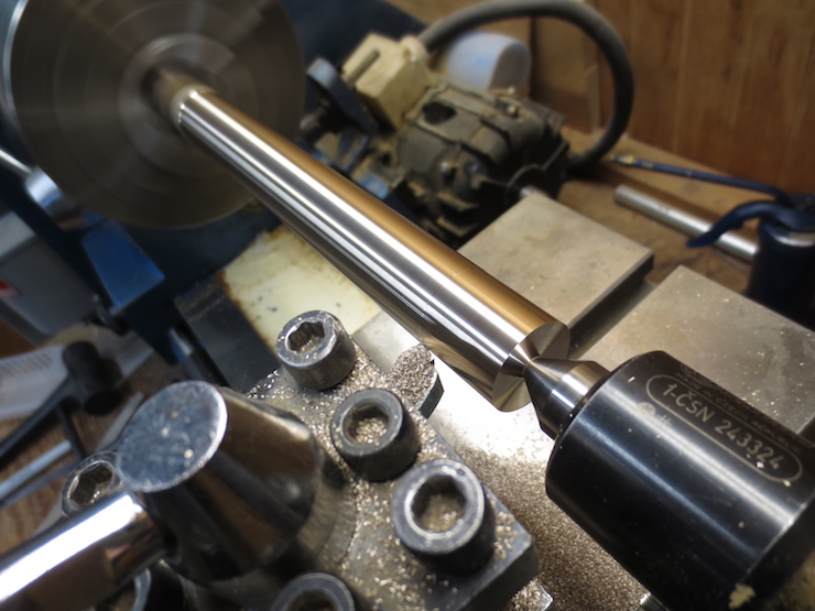
The final pass. The material is very easy to machine. This is the working end of the tap; it is turned to .875″ (7/8″) diameter to pass through a hole of the same size.

Next an inch and a half of the other end is turned to .750″ to fit the inside diameter of the shaft coupling that will be used to connect the tap to the master screw. This coupling (not pictured) has two inside diameters; 1.000″ on one end and .750″ on the other.
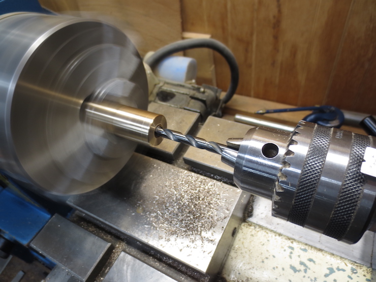
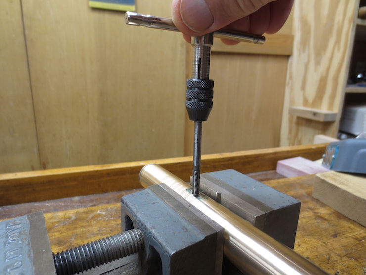
The working end is drilled with a 5/16″ diameter hole. This hole will be tapped (with a metal tap; the kind you can buy in a hardware store) to receive a 3/8″-16 hex head machine screw. This will allow the tap to be driven by hand with a bit brace and square drive socket.

Notice that the machine is unplugged. This is a hand operation. First the tap was chucked into the tailstock to align and start the thread. Then the tap is advanced by hand.

The tap body. The stripes were caused as the tap slipped in the lathe three jaw chuck as the metal tap was driven.
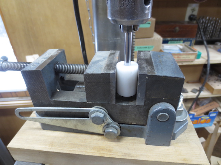
This is one way to center a hole in a shaft. The plastic rod has been turned in the lathe to the same size as the part to be drilled (.875″) and then drilled (while still in the lathe) to fit a drill rod (the shiny part in the photo). One end of this makeshift gauge is chucked into the drill press and the other clamped into the vise. This aligns the vise until it can be firmly clamped to the drill press table. When the bronze tap is clamped in the same vise (horizontally) it can be drilled crosswise exactly through its center.
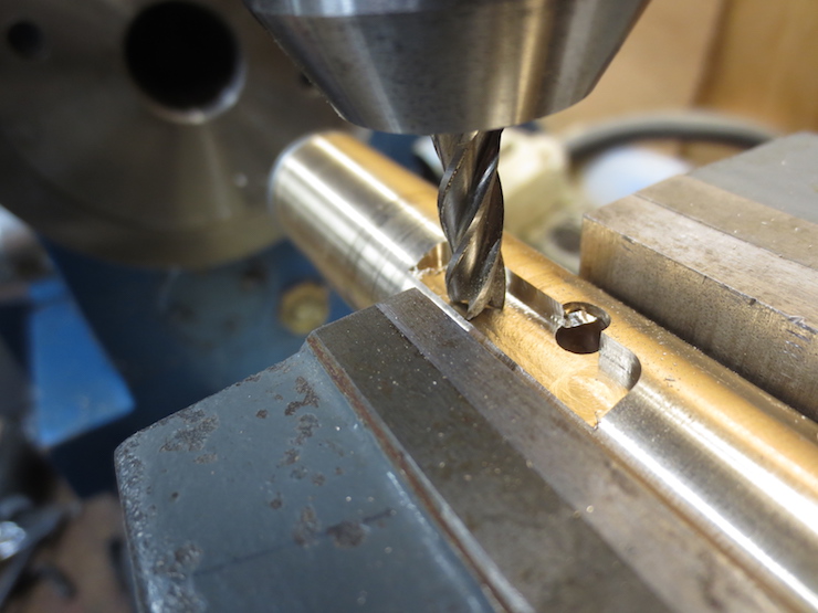
This ‘center drill’ gets the hole off to a good start so that the larger drill won’t wander.

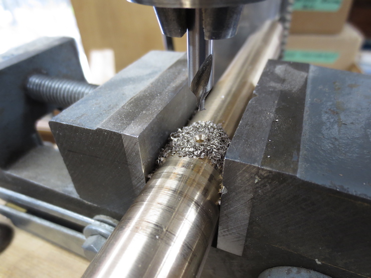
This drill is .201″ diameter and will drill the hole to receive the tap cutter which is made from .200″ diameter drill rod. The drilled hole passes right through the center of the tap at 90 degrees to its axis.

The cutter has been fitted but a set screw still is needed. Both 7/8″ x 5 TPI taps share the same cutter. This has the advantage of allowing the same gauge to be used for both. The gauge controls the depth of cut and allows the cutter to be advanced incrementally.
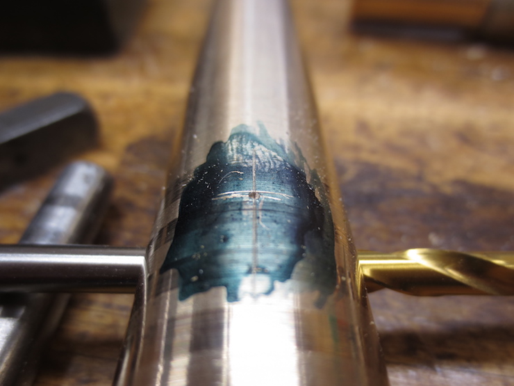
Here I have laid out the location of the set screw and punched the metal to help start the hole. The hole is drilled at 90 degrees to the hole drilled for the cutter.

Here the set screw lies alongside a tap with matching thread (10-32).
Tapping the set screw hole.
Milling a recessed area around the tap cutter to make room for the wood shavings that will pile up in front of the cutter as it scrapes.

The 3 jaw chuck had to be removed to make room for this operation.

In the wooden tap frame the plywood bearing/disc must be changed for different sizes of taps. Here the 1″ diameter one has been removed.
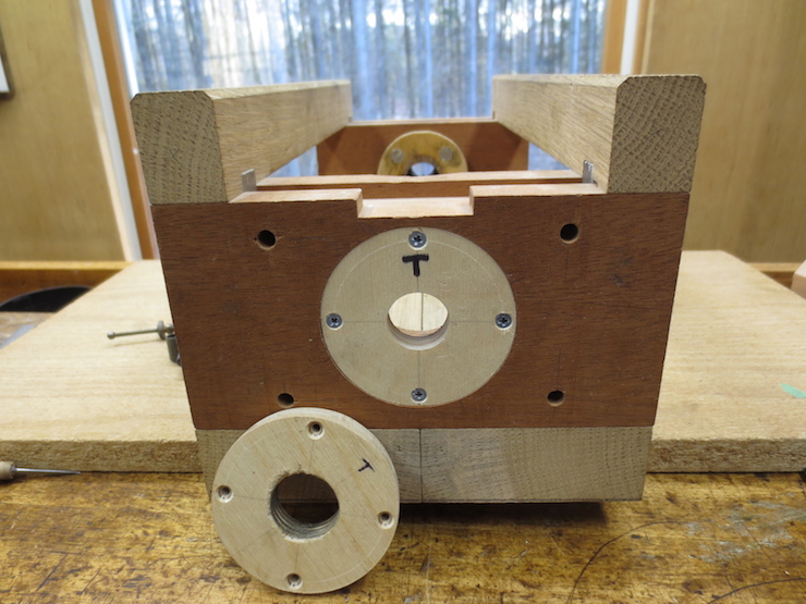
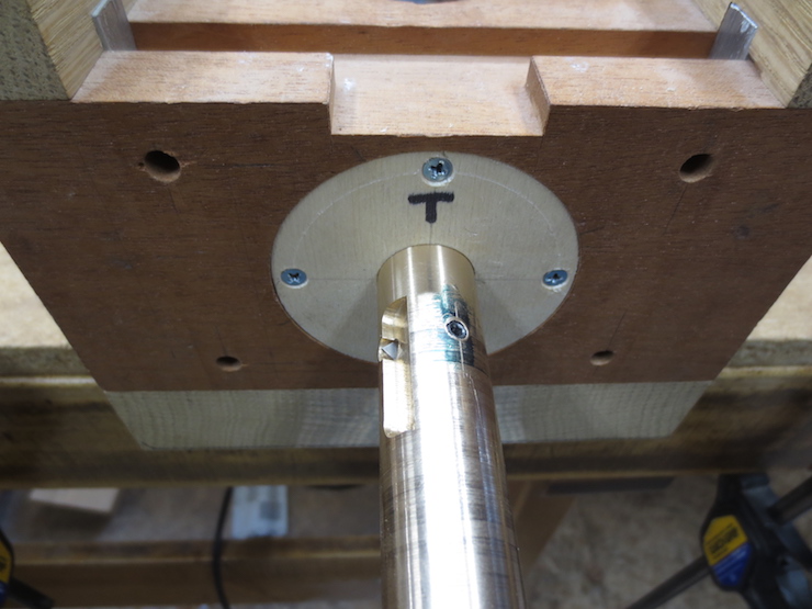
A new disc has been installed with a 7/8″ diameter hole to match the tap. It is now a simple matter to put in the new tap.
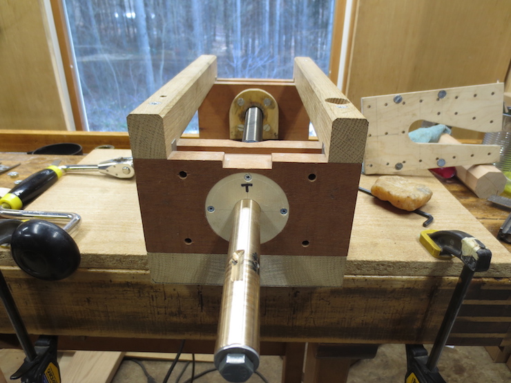
The master screw engages a brass nut at the back of the tap frame. The master screw and tap have been connected with a shaft coupling having a 1″ bore at one end and 3/4″ at the other.
To use the tap a wooden press body must be clamped to the front. The four 1/4″ holes are for bolting on attachments for various presses.
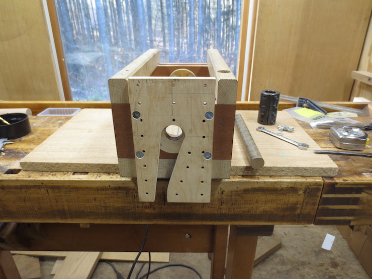
This perforated plywood piece is an adapter plate which makes it possible to attach necessary clamping arrangements at the front.
Scrap pieces have been screwed (from the back) to the adapter plate before it was bolted to the tapping frame. Other pieces are bolted on in turn to provide a way to clamp a pre-drilled press body to the front while being tapped. You can see this in the video “Using the Tap”.
