
The die that cuts the thread on wooden screws is the most complex part of the threading apparatus. Here the two main parts of the die are separated to show the innards. The main body of the die (in the back) fastens to the threading frame and serves two functions; it provides a channel to guide the wooden screw blank and a base for mounting the more complicated “shutter” (at the front) which is what I call the swinging part that contains the knife and the regulating mechanism.

Here the shutter is mounted in the body of the die but is open. The die is disconnected from the threading frame and is lying on its back.
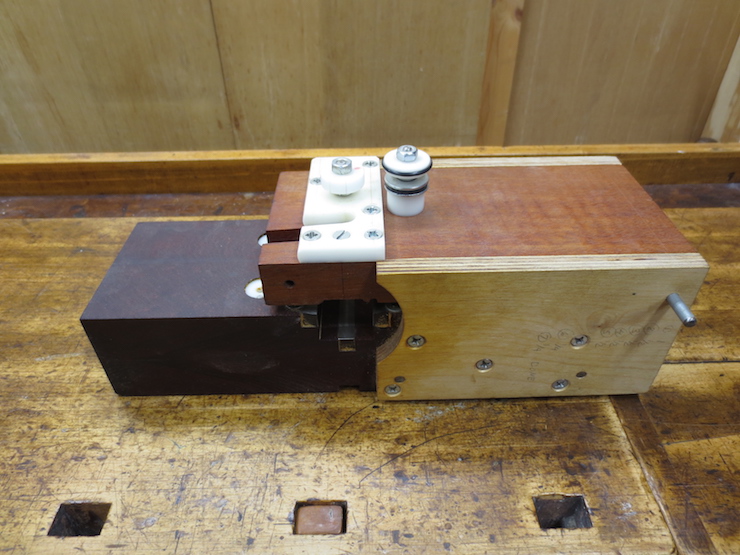
The die is closed. The taller knob at the right is for tightening the shutter onto the screw blank. The smaller knob controls the depth of cut.

The channel through which the screw blank is guided uses HSS lathe bits as wear bars. The wear from making many, many screws is visible on the middle bar.

This shows how the channel closely fits the screw blank.

The two part cutter is mounted at the correct Pitch Angle in the shutter. This angle is calculated using the circumference of the screw and its pitch (in this case 3 threads per inch or .333″). The white circles are the ends of acetal plastic cylinders. The two small ones are fixed stops which are set to stop the cutting when the thread has reached full depth. After the thread is fully cut the stops will ride on the surface of the screw and prevent the shutter (and cutter) from advancing further. The large cylinder is adjustable. When it is advanced fully the cutter cannot contact the wood. As it is retracted in stages the shutter will be allowed to swing inward and the cutter will be able to cut as the wooden blank rotates past it. The adjustable stop turns on a 1/4-20 thread and is adjusted in 1/4 turn increments. Thus the average cut is .0125″ or about 1/80″ or .33mm.

In this photo you can see the multiple cuts that were made to produce this 3 threads per inch hard maple screw.

The two parts of the cutter must be securely clamped together as the cutting action tends to force them apart. Here you can see how six set screws are used to clamp the parts sideways and two more set screws clamp the halves against the mount. Also visible at the top are two adjusting screws which control the position of the cutter halves.
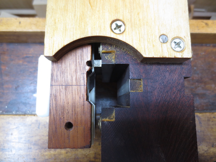
Here is a view through the channel of the die. The part on the right (the body) is screwed to the threading frame and does not move. The shutter (on the left) swings in a wide arc from a pivot at the top. If you look closely you can see that the adjusting stop (white) protrudes farther than the tip of the cutter so no cut is currently possible. If the stop is retracted the first cut can be made; a very slight spiral scoring of the blank. Between passes through the die the stop is retracted incrementally and the thread becomes gradually deeper until it is fully formed.

The cutter as seen through the slot through which the shavings are ejected. The screw has already been fully cut and backed up a bit to show how the parts relate.
The same screw as in the earlier photo. The shutter has been opened. You can see that the adjustable stop is completely retracted allowing the cutter to cut full depth. The two fixed stops are also visible.

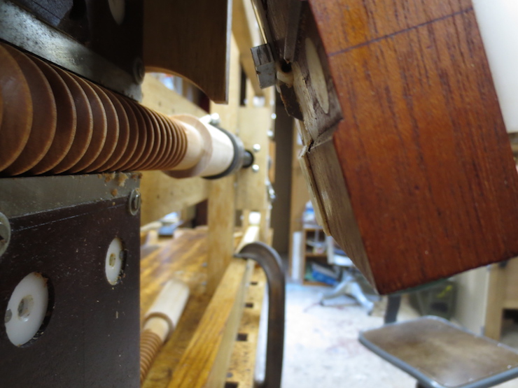
A different screw size and a different die but this shows what a screw looks like after the first pass through the die.

The same screw after its third pass through the die…
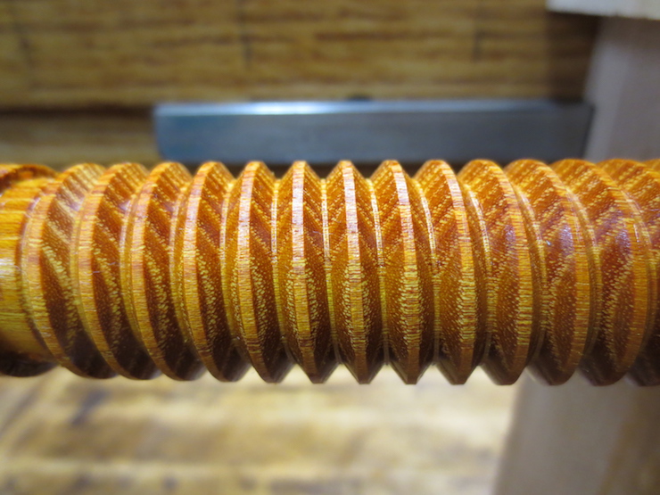
…and fully cut several passes later.
