


A die cutter is made from a pair of HSS lathe tool blanks. The blanks are square in cross section and around 2-1/2″ long. 1/4″ square blanks are big enough for my largest thread, 3TPI. A larger 2TPI thread would require 5/16″ blanks. My 4TPI die uses 3/16″ blanks and my 5 TPI die uses 1/8″ blanks. In future I would not use the 1/8″ size; it is difficult to make the clamping mount to hold the cutter in the die since there is so little space to locate the clamping set screws.
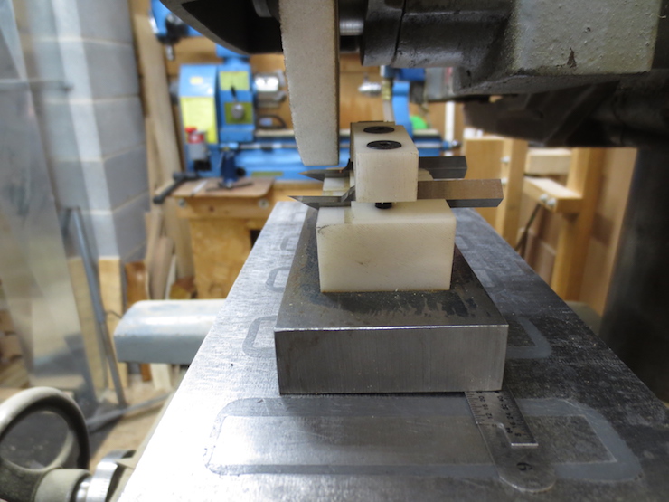
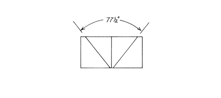
The most critical parts of the cutter are the two outside angled surfaces. These should be ground as smooth and flat as possible. They are equivalent to the back of a chisel or plane blade and will not be altered by honing. This jig grinds these surfaces to the proper angle for my 80 degree threads; 77-1/2 degrees. As you can see one edge of the jig is shimmed so that the magnetic chuck holds the jig at a slight slant to create a relief angle. The angled edge of the 77-1/2 degree cutter makes a shearing cut. Since the surface of the screw is curved the 2-1/2 degree reduction compensates for the shear to create an 80 degree thread. I adapted this cutter geometry from a 1977 Fine Woodworking article by Richard Starr. His cutter used a 57-1/2 degree angle with a 50 degree shear to make 60 degree threads. The machine is a Delta Toolmaker surface grinder that I bought on Ebay.
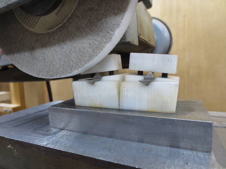
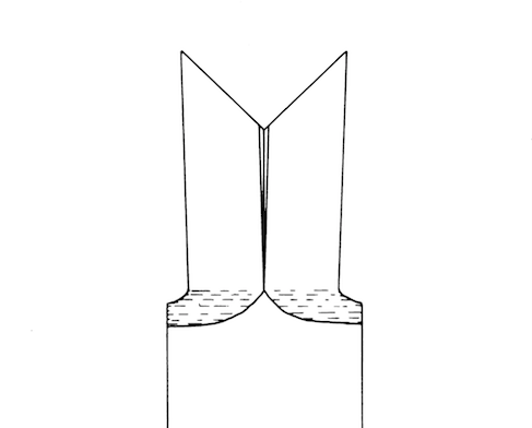
This is a mock up since I am not making a new cutter at present. I have clamped the halves of a completed cutter in the jig to show how it works. Normally this would be the first step in the process of shaping the blanks. The second step would be to grind a 50 degree bevel on the ends to establish the shear angle. Then the inside bevels would be ground away to produce the sharp cutting edges.
The finished cutter must be set in the die at the pitch angle of the screw which is to be made. I calculate both major and minor circumferences of the screw. Then I make a scaled up drawing using these and the pitch to find two angles. Set the cutter between these two angles to give more or less equal clearance behind both cutting edges. The midpoints of the cutting edges at full depth (the parts actually engaged in the wood, not including any unused portion at the wings) should approximately bisect the center line of the screw being cut.
