This is an overview of the development of the methods I now use for making wooden screws.
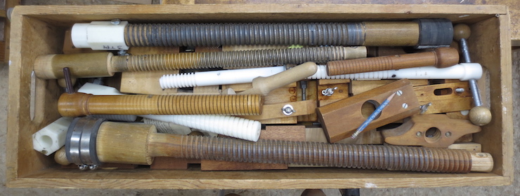
Above are taps and dies that were made using a 1977 Fine Woodworking article. In this traditional approach a tap is first made and then used to make a die.
I was immediately drawn to this FWW article when the issue arrived in the mail. I didn’t attempt making these tools until the early to mid 1980s when I was living in Madison, Wisconsin. My spouse, Pati Scobey (www.patiscobey.com) was in grad school at UW-Madison studying under Warrington Colescott and Walter Hamady. Book Arts were a major part of her studies and this encouraged me to pursue making paper moulds and later bookbinding tools. We rented a small house next door to Ace Hardware on ‘Willy’ Street which turned out to be very convenient for an aspiring inventor.
The screws made with these tools were not very satisfactory. I wanted a dependable way to make high quality wooden screws to make book presses for sale. At least half of the screws were unusable with badly chipped threads. I put my screw making ambitions on hold for a few years and concentrated on making paper moulds.
Around 1996 I was asked to give a workshop for Paper and Book Intensive. By this time we were living and working in Michigan. I had already taught a workshop in paper mould making for PBI in 1993. I received a phone call from Pam Spitzmueller inviting me to teach and it was she who suggested the topic of making finishing presses for bookbinding. Very soon after I received a call from Tom Conroy (who I had never met). He generously offered a lot of very good advice about what makes a good finishing press. He also mailed me copies of his extensive notes and drawings and a copy of an article by Derek Beck which I found particularly helpful. (Derek Beck, New Bookbinder, Issue 1, 1981). What seems amazing in retrospect is that I agreed to teach this class without actually having any workable tools and methods to make wooden screws! I was 41 years old; evidently still young and foolish enough to give it a try.
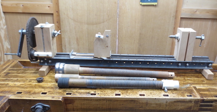
This contraption was the next attempt at making wooden screws. It was built with the intention of using it for the upcoming class. It is a sort of hand powered machinist’s lathe complete with a lead screw and moving tool post. By changing the chain sprockets it was (in theory) able to produce threads of several different pitches including two, three and four threads per inch. It was obsolete from the beginning. Friction (a lot of it!) was a major problem as was excessive play in the lead screw propelled tool post. However I was able to eke out 3 wooden master screws (in the foreground) which became essential working parts of the next threading device. As it turned out these wooden master screws were used to make hundreds of press screws before they also became obsolete.
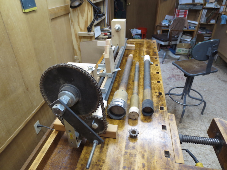
Another view of the lathe and the three master screws produced on it. You can see that the wooden master screws have been well used.
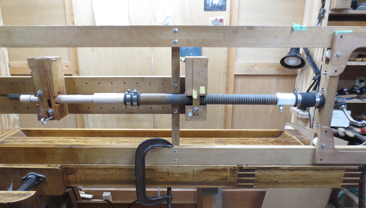
This is the first tool that could actually produce very nice wooden threads. It is one of two threading frames that I took to Penland in North Carolina to teach the PBI class. It uses one of the wooden master screws to make a 4 TPI screw. By this time I had discovered how to make a two part die cutter (very exciting!) and the method used here is basically the same as what I use to this day. Since then it has been a process of refining things to make the method easier and more reliable.

The 4 TPI threading apparatus shown along with the original taps for 4 TPI and 3 TPI screws. There was also a larger tap for threading a 1-3/8″ diameter hole for a small lying press. Not shown is a larger threading frame that could make both 1-1/4″ 3 TPI and 1-5/8″ 3 TPI screws. I still use all of these pitches and sizes. We used the same router lathe that is pictured in other pages to prepare the screw blanks. The process was very successful; we made a lot of presses. But it was slow; the threading was driven by hand with the knobbed crossbar and the router lathe had to be cranked by hand.
Back at home I now knew that I could make good wooden screws but it was obvious that things needed to be speeded up a bit. The next idea was to drive the tap and die with a bit brace. When using the die the brace was mounted in a wooden rack that travelled along on ball bearing drawer glides (not pictured). The tap could be driven by hand with the cross handle or with the bit brace by means of the bolt head on top. This turned out to be a brief transitional phase that led to the next advance shown below.
This involved making this ‘universal’ threading frame. It was designed so that various dies and master screws could be bolted on to produce a wooden screw of any pitch. As you can see parts of the original threading frame have been cannibalized from the earlier version for use with this tool.
I made a lot of wooden screws with this set-up. The original wooden dies were capable of making great threads but wear from use was a constant concern. As the parts of the die wore down the adjustment of the die had to be closely monitored to produce consistent threads.
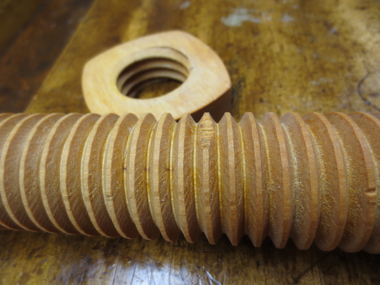
I kept the wooden master screws lubricated with beeswax. You can see the paper shim added to reduce side-play which, if excessive, causes the thread to be ruined.
The half nut which was tightened against the master screw.

Inside the nut. Wear was always a concern.
For the wooden master screws to work well they had to be firmly fitted to their nuts without play. this made for quite a bit of friction. I can’t remember when I thought of switching to steel master screws but it was a wonderful solution. The friction was dramatically reduced making the screw blank much easier to drive. And there was no significant side-play to worry about. These steel screws aren’t cheap but their use transformed the threading apparatus into a very efficient hand powered production tool.
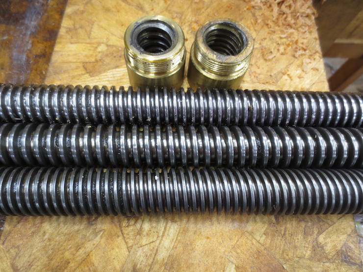
Steel master screws with matching brass nuts.
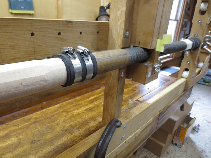
Serendipity played a role. Standard screws with 3 TPI and 4 TPI came in 1″ diameters; the exact size of two of the taps I was already using. So I could purchase 1″ diameter steel shaft to join to the master screws to make new and better taps. Also, the standard 1″ inside diameter shaft coupling had the same outside diameter (1-3/4″) as the large connecting ends of the wooden master screws that it replaced. These are the ends that fasten to the blanks with radiator hose (above center). So after making a wooden block (above right) in order to mount the nut and flange to the threading frame everything pretty much just bolted together and dropped into place.
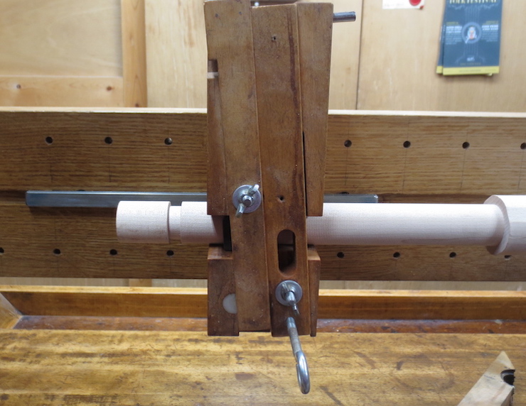
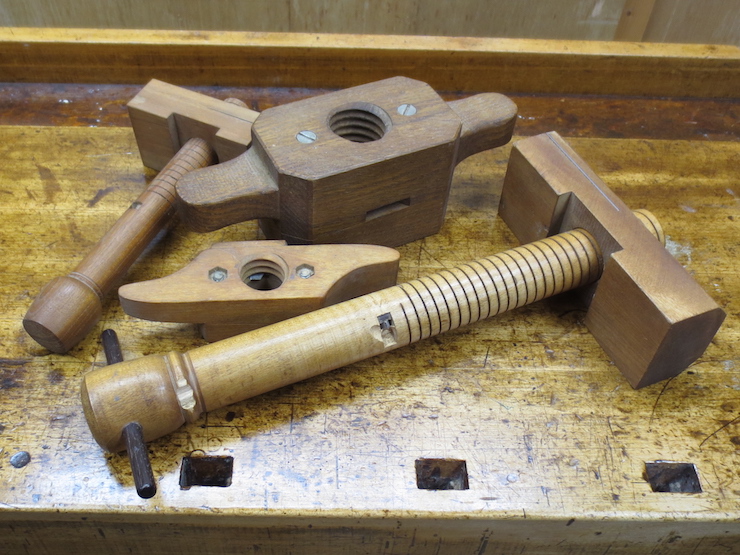
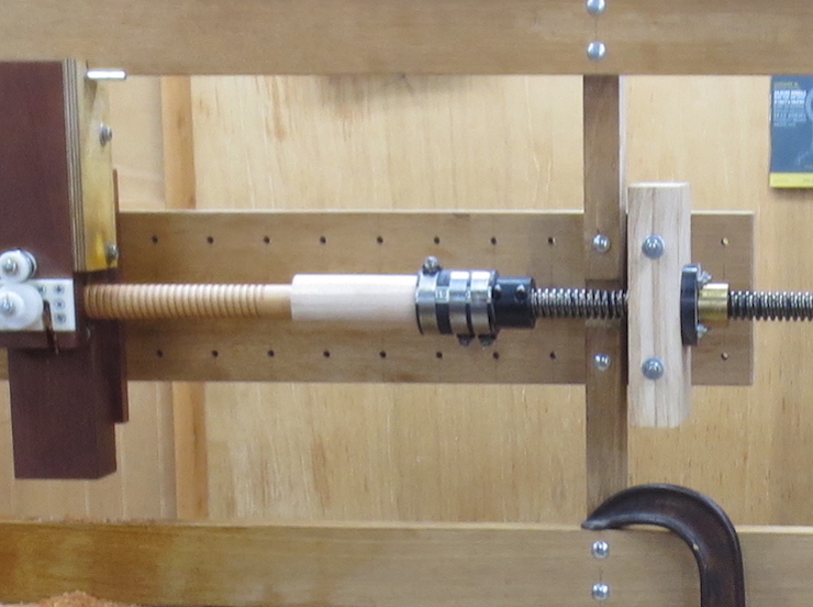
The last step was to re-think the design of the dies. The original dies controlled the thread depth by adjusting the position of the cutter in relation to the slot in the die that the blank passed through. These tools were simple to make but fussy to use. The screw needed to be held firmly against the back wall of the slot by the pressure bar on the left. The depth of cut was controlled by the eye bolt at the bottom right. Each time the eye bolt was adjusted the wing nut above it needed to be re-tightened also. And for reasons difficult to explain the pressure bar needed to be constantly re-tightened too. (The pressure bar surface and die surface wore unevenly due to the multiple passes of the screw as the thread became progressively sharper.)
Another view of the original die.
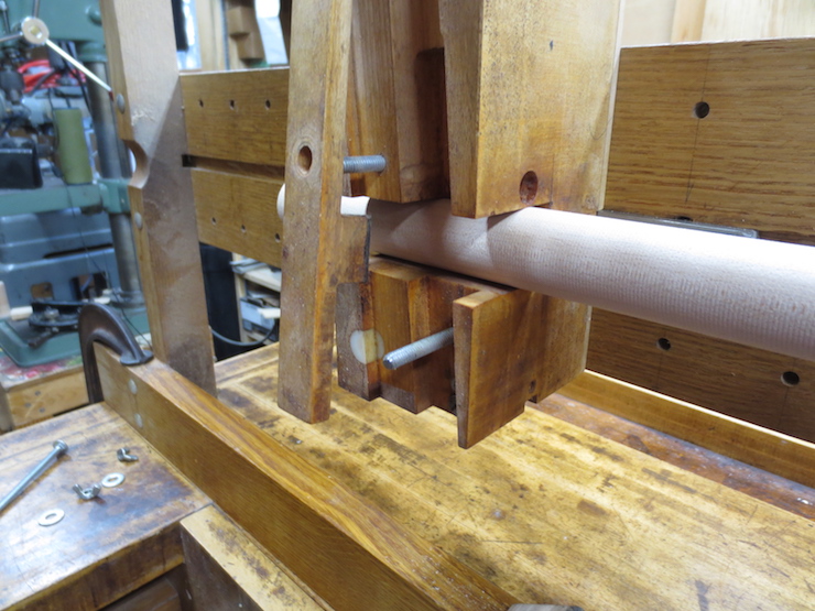
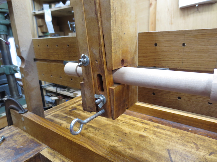
Parts removed to show the structure.
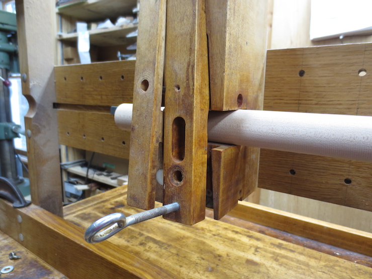
The pressure bar on the left would press on the surface of the screw blank to keep it against the back of the slot. The cutter mount would be adjusted IN RELATION TO THE BODY OF THE DIE (compare with below).
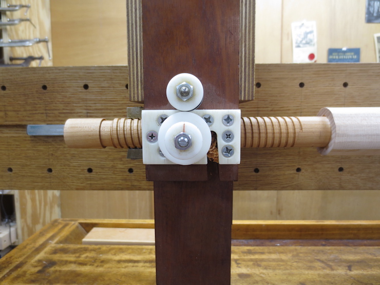
This new design turned these concepts on their heads. The cutter and adjustment mechanism are incorporated into a single hinged shutter that is adjusted IN RELATION TO THE SURFACE OF THE SCREW BLANK. An adjustment disc has dual functions of limiting the cut while at the same time pressing against the screw blank to keep the cutter engaged. When the thread has been cut to full depth two stops contact the surface of the screw to prevent any further cutting.

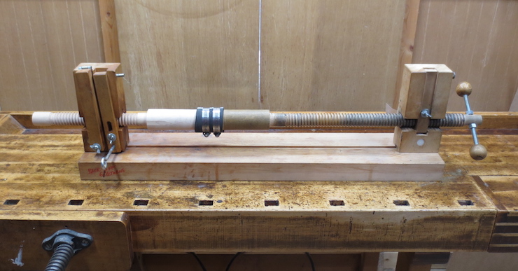
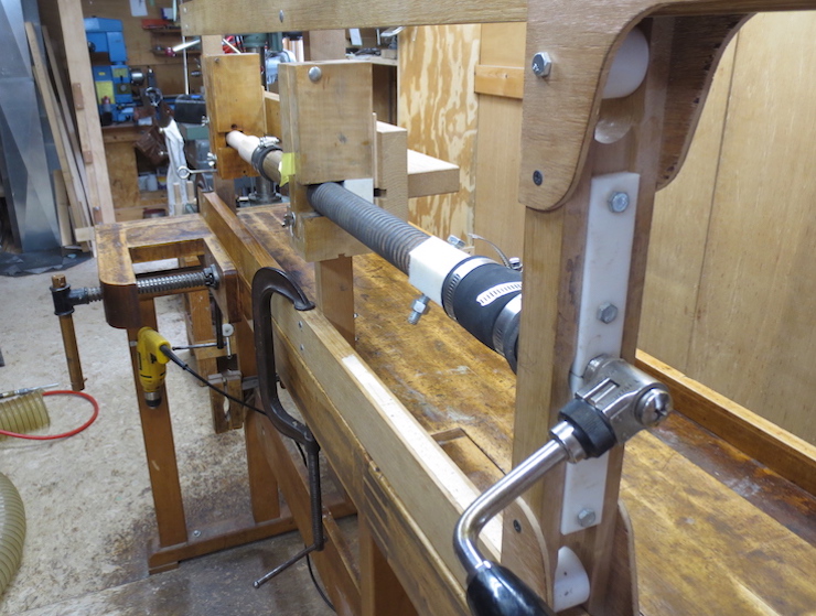
The culmination of years of incremental progress. Here is my current threading frame including the die pictured above and steel master screw.
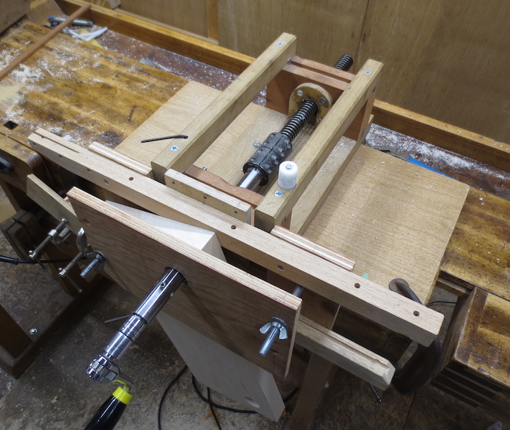
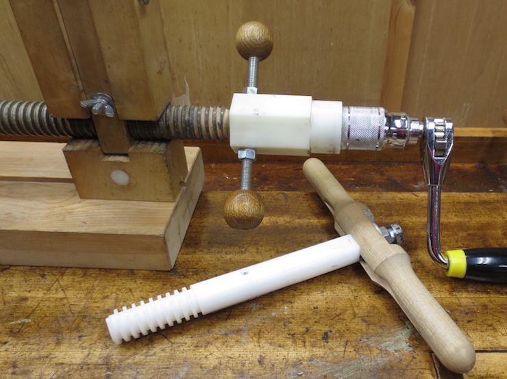
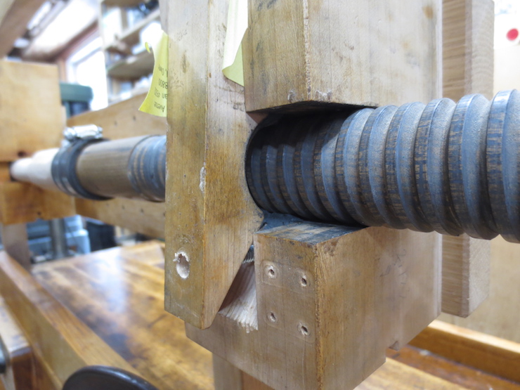
The taps are also now guided by a master screws to produce internal threads. This makes for a much more efficient method than what came before.

The rear of the tap showing the placement of the flange and brass nut. The nuts for various master screws can all be threaded into the same flange making it easy to change screw pitches.
Summary
The process for making wooden screws that I’ve presented in a dozen or so pages of the website is the culmination of many earlier efforts, including many mistakes and a few dead ends. Only this last method employing ‘off the shelf’ steel master screws and fittings along with custom made taps and dies achieves a truly workable method of production suitable for a small cottage industry making wooden book presses or other similar tools.