The wood for making Paper Mould frames has been prepared to make pieces that are relatively stress free and stable. Now the stock will be shaped to its final dimensions prior to cutting to length and joining at the corners with dovetails.

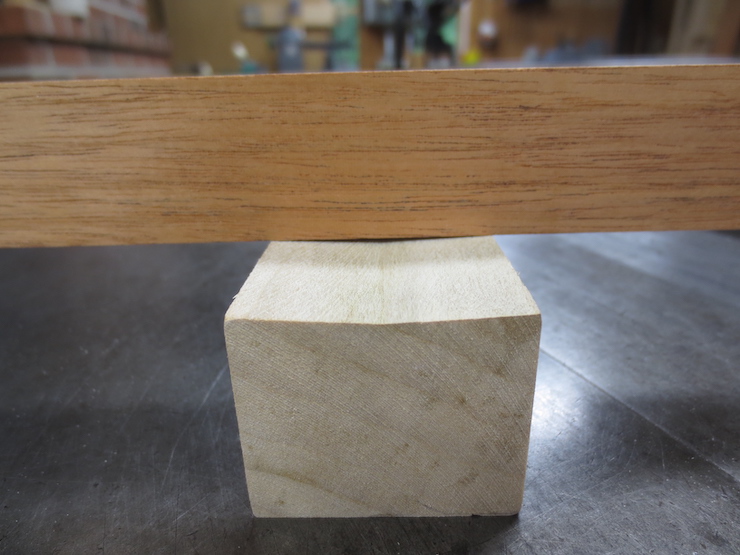
Shown above is a block of poplar that I shaped to demonstrate the method I use to make the frame pieces of even thickness. I used exaggerated angles to make it easier to see.
To begin one side of each frame piece is jointed perfectly flat on the freshly sharpened jointer. I am experimenting with better guards for machines to make them safer to use.
Next one edge is also jointed perfectly straight and at exactly 90 degrees to its previously jointed side.
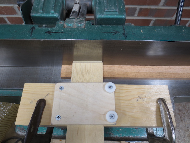
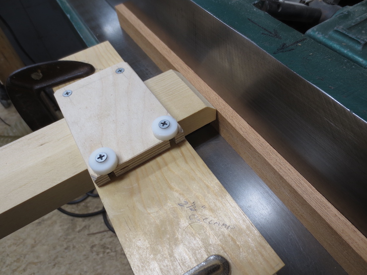
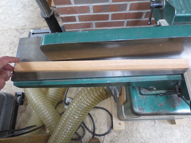
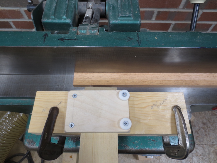
The wood rests on its newly flattened side with the jointed edge against the tablesaw fence. It is sawn (with the rip saw of the previous post) at precisely 90 degrees to the jointed face. The fence is set so the pieces end up about .015″ (1/64″) wider than the intended final width. They will all end up exactly the same width and the slightly rough edge will be left that way until after the joints are cut. This makes it easy to identify the bottom edge of the mould frame. It also helps avoid mistakes as the pieces are put through all of the steps to create the dovetail joints. Even though the sawn edge is rough it leaves a precise, square, straight edge to measure against. The wooden feather board pressing on the piece being sawn means my fingers don’t get close; a push stick is used to finish the cut.
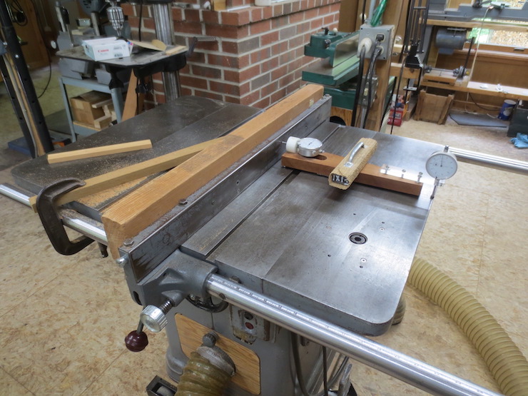
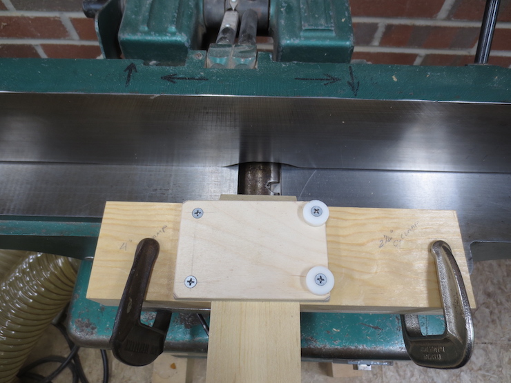
This photo shows how the home-made dial indicator fixture can be used to help adjust the fence very precisely. As the fence is moved laterally, the dial on the left will measure the change.
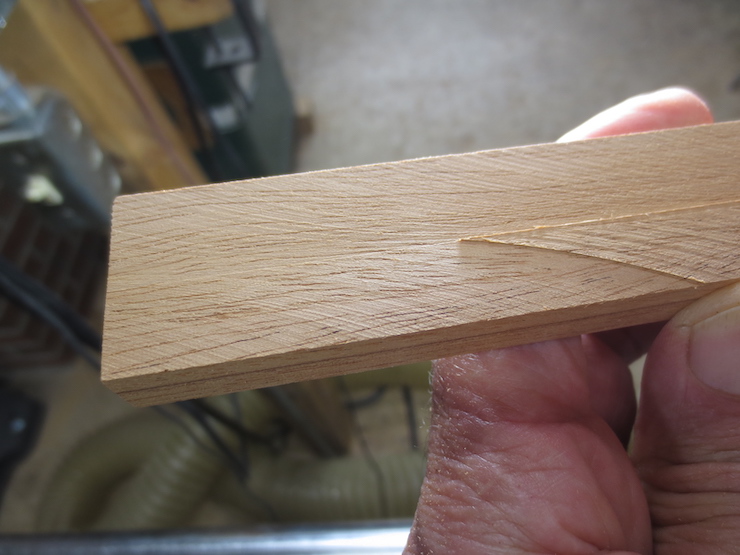
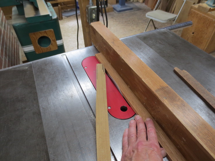
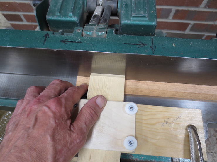
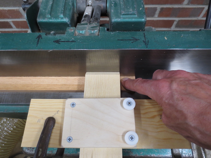
The first step to thickness the wood uses the rip saw raised to just over half of the width of the frame pieces. It is set at a slight angle; about 1/3 of a degree. Each piece is sawn in two steps to create a very shallow V-shaped depression. This piece was withdrawn partway through to show the process.
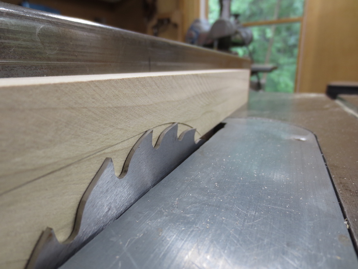
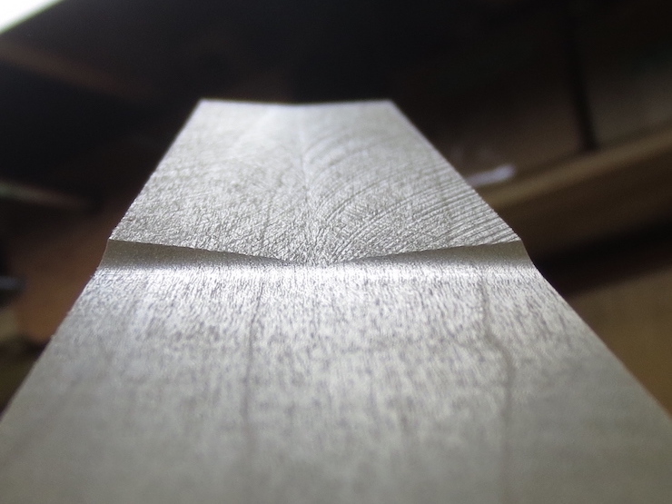
You can see the shallow V-shaped space when a straight edge is placed there.

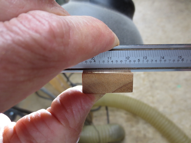
If the saw is sharp and the fence is straight this will leave edges that will measure exactly the same width all along the length. When placed rough side down on the jointer only the outer edges will touch the table. When pushed through the jointer the pieces will be planed to a precise thickness. It works very well! Here a test piece is used; first sawn and then jointed at the end. This is measured with the vernier calipers to see how much the table saw fence needs to be adjusted, with the help of the dial indicator, to achieve the desired thickness.
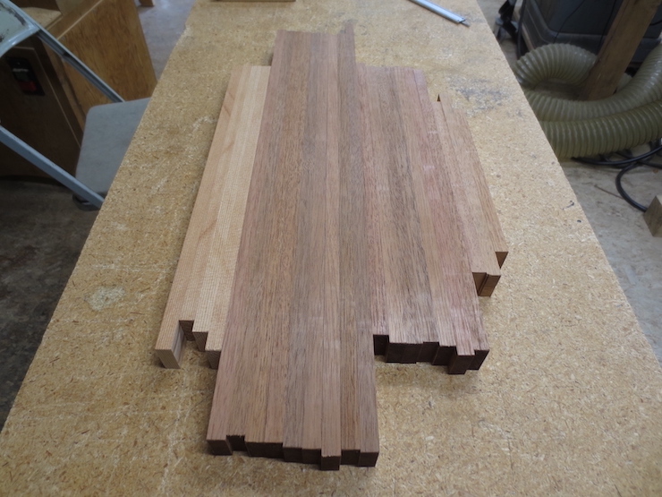
The mould frame stock is finished and ready to cut length. Each piece has one rough side and three smoothly jointed sides and all are virtually identical in thickness and width. And, as you can see, the pieces are very straight.
More detail
To test to see how well a jointer is working see how a freshly jointed piece acts by gently moving one end as shown in these two photos.
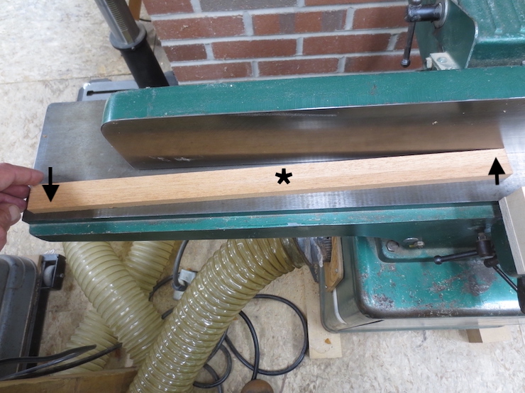
If the piece pivots on the middle as above the piece has a ‘belly’. The star indicates the approximate pivot point.
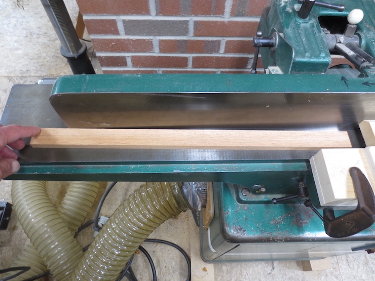
These two photos show a better outcome…
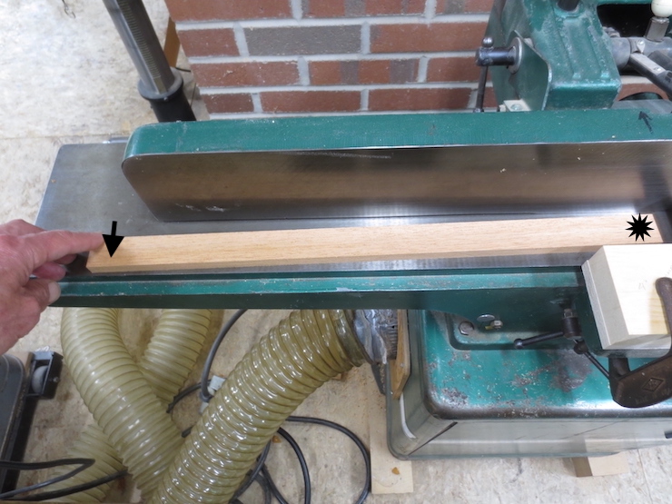
One end will move and the other stays in the same place. It pivots near the star at the right. This shows that the piece is hollow (microscopically) but this is better than having a belly. Woodworking planes work this way. If you are preparing to join two pieces of wood, set the plane for a fine cut and try to make the edges hollow. The tool will not allow that to happen (except to an insignificant degree). The next 4 photos will attempt to show a machine process of slightly hollowing a piece first, then jointing it flat. It ends up sounding kind of insane but what I’m trying to describe becomes pretty intuitive once you get the hang of it.
The guard is opened so the piece to be worked can be dropped in. The jointer is set to a very fine cut; about .005″-.010″. This is possible because the wood is already very flat.
The workpiece in place with about an inch hanging over the out-feed table.
The guard is pushed in and with light pressure at both ends the piece is started here, moved fairly rapidly from right….
…to left and ending in this position. The ends aren’t trimmed at all. This is repeated 2 or three times and has the effect of slightly hollowing out the middle, while removing any ‘hump’ or ‘belly’. Don’t move the guard, just pull the piece back through to start again. You can hear and feel when the knives can no longer reach the wood to cut any more. Then the piece is pulled completely out to the right, lifting slightly to clear the knives. This sounds harder than it is. Being slightly hollow the piece now rests on its ends so it can move into the cutters without any tendency to rock. As the left end of the piece slowly passes the knives a true plane is established on the bottom edge of the wood which continues to move along to rest on and be supported by the out-feed table. As the board is slowly fed past the knives, that plane is extended until the right hand end leaves the in-feed table and passes the knives, finishing the cut. This is repeated one more time to remove a slight ‘divot’ that will likely occur at the left end; this last pass especially being nice and slow.
The thicknessing method.
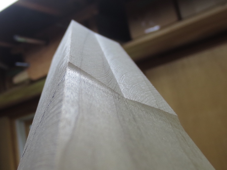
Here is the previously mentioned poplar demonstration block being sawn at a slight slant. I set the saw at 3 degrees (instead of the usual 1/3 degree) to make it easier to see. The usual angle is somewhat arbitrary, just enough to create two clean edges for the wood to ride on without having to joint too heavily to remove the saw cuts.

Partially cut.
The hollow is visible beneath the straight edge. When the piece is turned over only the outer edges will ‘ride’ on the jointer table as the saw cuts are planed off.
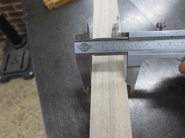
Measuring the thickness at numerous places along both edges with this vernier caliper showed variation of less than .001″. (1/40mm) The measurements hardly strayed off the line possibly showing variation closer to +/- .0005″!
After jointing a smooth face replaces the rough sawn one.
Measuring wood in thousandths of an inch might seem ridiculous. But being able to control dimension with basic low-tech tools is kind of satisfying. And it makes the later steps easier. Wood will always move; these ‘perfect’ pieces of wood will not stay that way but they will likely be closer. I am convinced that the care taken now pays off in the long run as the pieces of a mould end up being more ‘relaxed’, each doing its part and not working at cross purposes. At least not as much.
The question comes to mind: “Why not just use a thickness planer?” Early on I did. Even for ribs, though that was soon abandoned. The rollers mashed one side of the wood and distorted it. Probably the need to find a way to make the delicate ribs without damaging them led me to this way of making the frame stock. I can’t remember the entire process of discovery.
In my shop a thickness planer is a valuable tool but I have not sharpened mine in years! It is a lot of trouble to change the knives. I use it to save time when shaping larger pieces of wood. If wood is jointed or planed with dull knives the edges are actually ‘pounding’ on the wood as well as cutting. This smashes and bruises the surface. When the wood gets wet smashed areas will swell and rise up making the surface rough. Wood cut with very sharp tools won’t do this as much. I hardly do anything to smooth the wood of a paper mould after the wood work is done. Edges are slightly rounded with a plane and the outsides are smoothed just a little with a fine sanding sponge.
More on the thicknessing method.
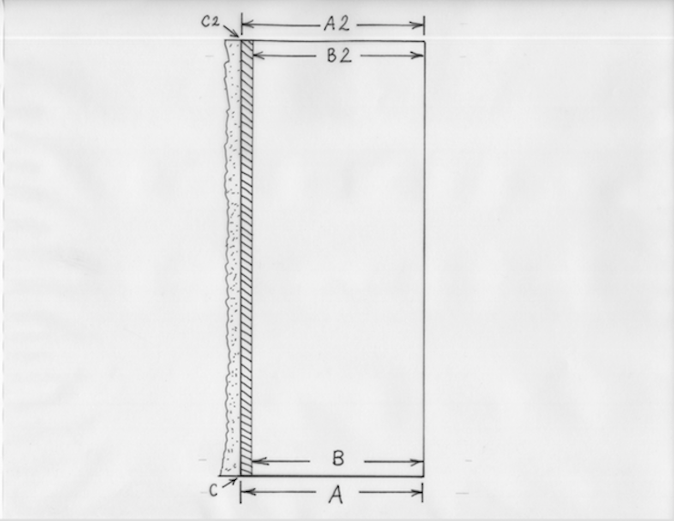
In the drawing above the rectangle on the right represents the desired final width dimension (B) of the mould frame in cross-section. On the left the rough, DOTTED area represents the part to be sawn off. This in preparation for planing off (on the jointer) the DASHED area. If you try to saw the frame stock to width in one pass some problems may occur. To make the bottom dimension (A) the same as the top dimension (A2) will take very careful adjusting of the tablesaw. No matter how careful you are the two are not likely to end up the same. For one thing at the top edge of the wood (along C2) the circular saw blade will be cutting 1-1/4″ to 1-1/2″ above the tablesaw surface while along the bottom (at C) the wood will rest on that surface. Dimension “A” is likely to remain very consistent while dimension “B” may vary a bit with slight differences in pressure as the wood is fed through the saw. Circular saws can ‘flutter’ which is likely to cause a slightly more irregular cut at the top than at the bottom. This may leave a surface that is not functionally flat; it may rock slightly on the jointer. If it rocks at all, the thickness will not be consistent after the rough saw marks are planed off.

Trimming the frame piece from both sides with the saw set at a very slight angle reduces or eliminates these problems and it’s so easy! First there is no need to carefully adjust the tilt of the saw to try to make the top and bottom edges equal in one pass. The tilt of the saw is not at all critical; just enough to create the shallow depression along the center but not so deep that an excessive amount of wood needs to be planed off. (About 1/3 degree for moulds) The saw cut only needs to be half as deep so there is less opportunity for a ‘wobbly’ or ‘fluttery’ cut. Dimension “A” at BOTH top and bottom is defined by the distance between the fence and the saw blade at the level of the table. This is as accurate as you are likely to get on a tablesaw. Since the jointer knives are set to very close tolerances the two sides will end up virtually parallel. When being pushed over the jointer the piece rides on the edges only (C) so it can’t rock.
For yet one more attempt to explain this in words check out my reply to the comment posted below.

I’m still not sure what purpose the V shaped depression serves. I’d think removing material by jointing a flat surface would be more accurate than riding on the outer edges of a V cut. Plus, isn’t it difficult to determine what angle to use so that the V cut is the right depth and is fully removed while arriving at the final desired thickness?
LikeLike
Thanks for the comment Brian. I tried to make things a little more clear by adding a couple drawings and more text to the post. Not sure it will help though. In a few words this method: (1) is fairly easy, (2) insures that both narrow sides of the blanks are exactly the same dimension (since the wood is cut from both sides in the exact same way), (3) doesn’t require careful adjustment of the saw angle, (4) requires a less deep (safer) cut, and (5) leaves a slightly concave surface to insure that the blank will rest accurately on the jointer bed and won’t ‘teeter’ on a high spot (left inadvertently by a circular saw blade ‘vibrating’ or ‘fluttering’). After a test piece is run purposefully oversized the remaining adjustment is made either by lowering the in-feed table of the jointer or moving the tablesaw fence. In either case the dial indicator is used to set the adjustment. It works!
LikeLike
Thanks for a ggreat read
LikeLike