The wood for moulds, ribs and deckles has been seasoned, straightened and trimmed to near final dimensions. At this point I pause to get the necessary tools tuned up and ready to go. (I’ll post general information first, and include more detail at the end for those who are interested). These are current sharpening methods for the tools I depend on the most.

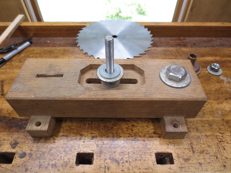
This 8″ Hollow Ground Planer saw blade plays a major role in my method for making paper moulds. Many sharpenings have reduced the diameter of the saw which started out exactly the same as the new one behind it.
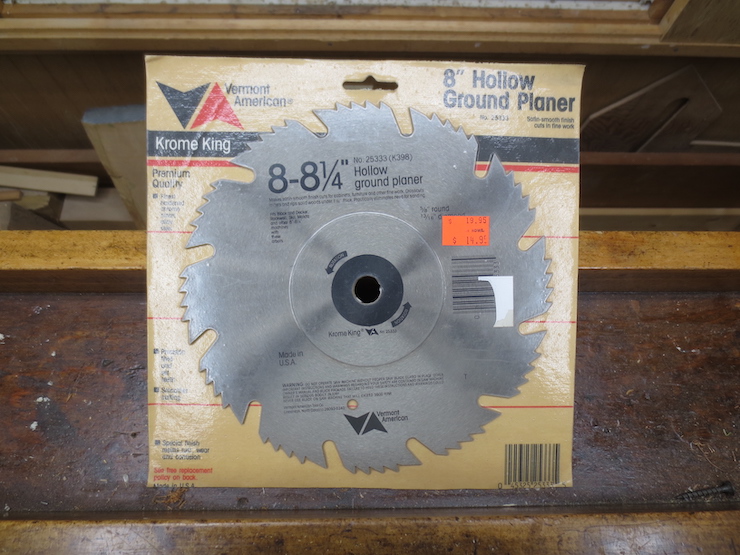
I found a few of these on Ebay. I don’t know if they are still made.
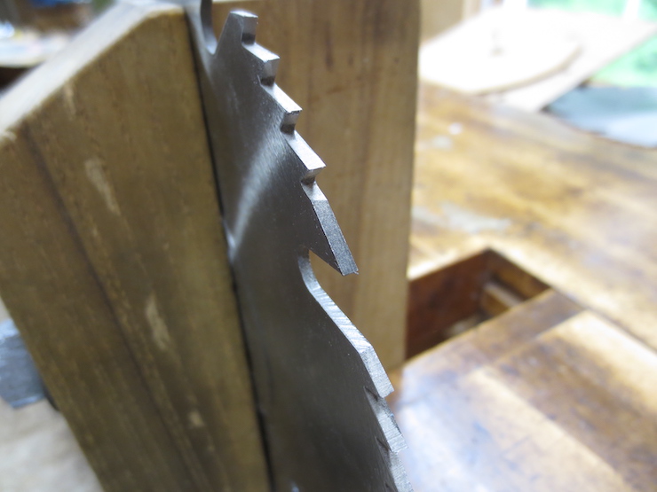
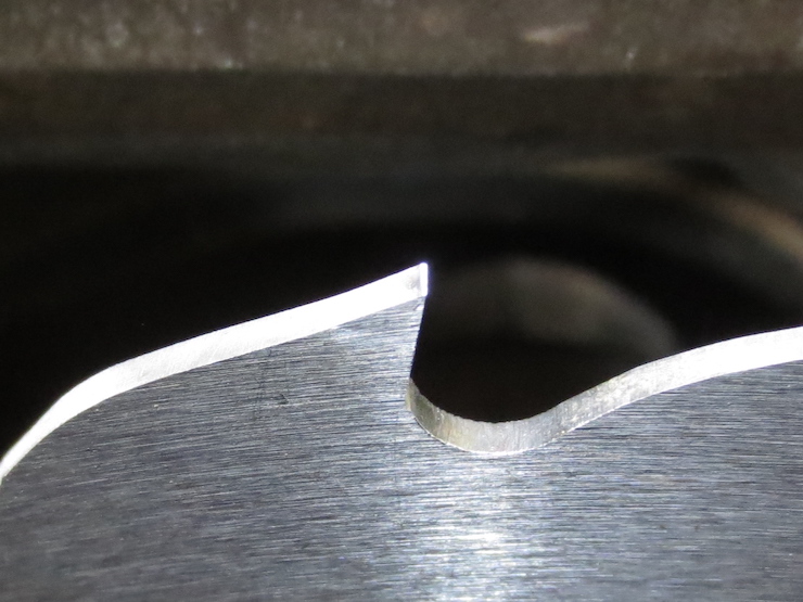
When the saw is new the teeth are all filed nearly straight across like this and it doesn’t cut well.
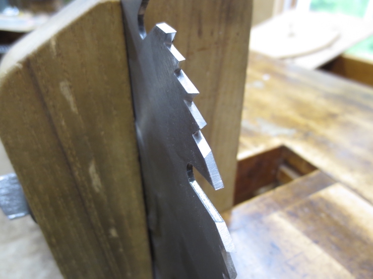
The teeth should be filed at 15 degrees like this. Every fifth tooth is a raker which is filed straight across and at a lower level to cut slightly below the tips of the cross cut teeth. This blade cuts very smoothly and I use it a lot for the finer work making moulds. Steel isn’t as hard as carbide but is less brittle so the the teeth can be shaped to sharper points. It seems to cut more freely and with less chip-out on the relatively soft woods used for moulds.
This is a rip saw. Its teeth are all shaped like little chisels and it is used for cutting wood parallel to the fibers (‘ripping’). I’ve learned how to use it in combination with a sharp, well-tuned jointer to create perfectly straight pieces of perfectly even and consistent thickness. This and the hollow ground planer are the only two saw blades needed for making moulds.
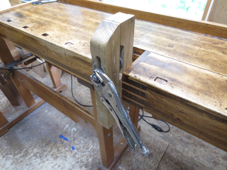
This is my home-made saw filing vise which is used to keep both types of saw sharp.

This is a home-made stake and anvil that I use occasionally to put ‘set’ in the teeth of the rip saw. Used with a hammer and punch this tool is used to bend the tips of the teeth to create set. The cut made by a saw must be wider than the saw’s body to prevent binding. The anvil is just a hardened bolt with its outer edges ground off to provide an angled striking surface.
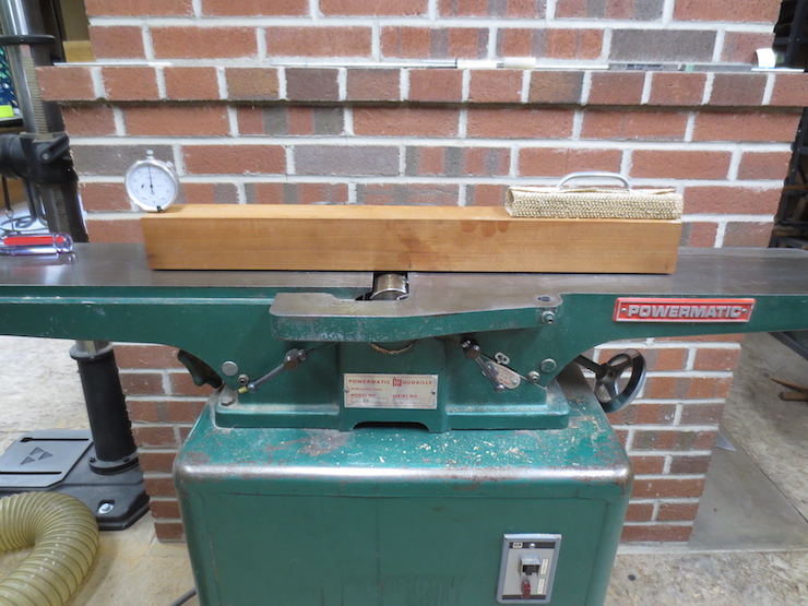
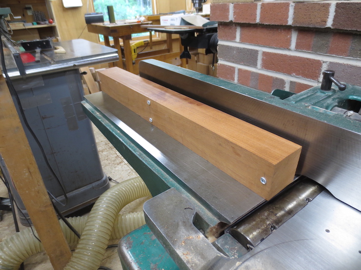
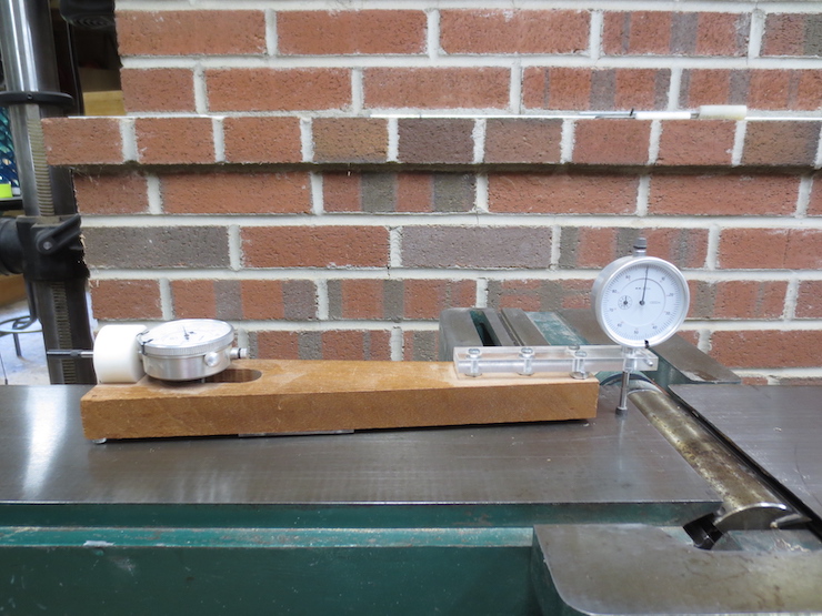
A very sharp, well tuned jointer is essential for this method of making moulds. On top is a very simple tool that holds a dial indicator to check for proper alignment of the in-feed and out-feed tables of the jointer.
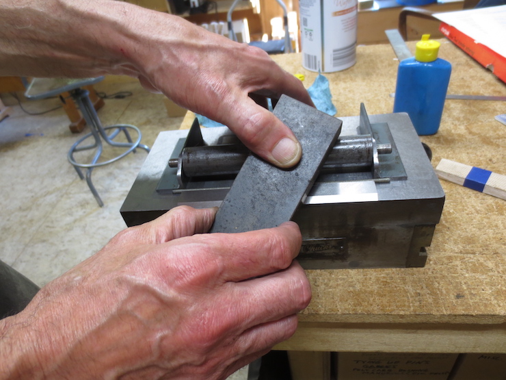
There are countless ways to sharpen. I have recently discovered a very effective way to hone jointer knives. I purchased an old surface grinder some years ago to help me make bookbinding tools. It came with a magnetic chuck, shown here dismounted from the machine. The top surface is perfectly flat and can be turned into a powerful magnet with the turn of a lever. This can hold the jointer knife as well as this roller assembly firmly in place to create a controlled honing angle. A more detailed description is given in the second part of this post.

Another simple shop-made device holds a dial indicator for setting the jointer knives. This tool also gets used a lot for making small adjustments when using the tablesaw, jointer and router table.
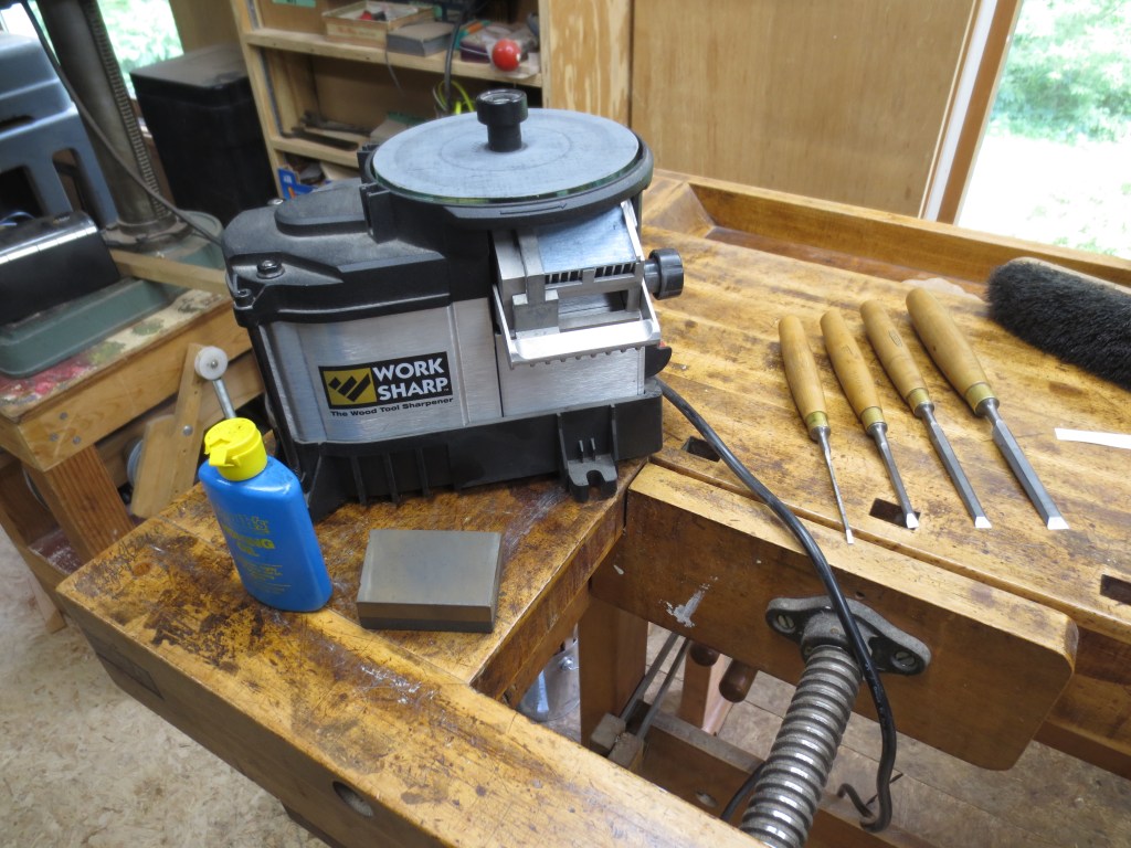
This machine works very well for sharpening the narrow chisels that I use for paper mould work but I wouldn’t recommend it for much else. I’ll use the four chisels shown for paring the dovetail joints of the mould frames and for detail work on the deckle joints.
A Deeper Dive…
The information given above just scratches the surface. Below is more detail for those who are interested. There is still much more to know and to discover.
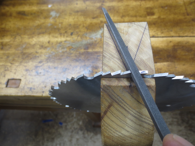
Marks on the saw vise show the correct angle to hold the file. The saw must first be ‘jointed’ on the tablesaw. The saw is set for exactly 90 degrees and lowered so the teeth are just below the table surface. A carborundum sharpening stone is held directly over the saw blade. With the machine running the saw is raised EXTREMELY slowly until a few sparks are visible. (Dim the lights). This will dull the teeth slightly so that all are at the same height. The teeth should be altered the smallest possible amount. Only enough to show a tiny shiny spot on each tooth (minus the rakers).
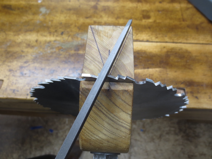
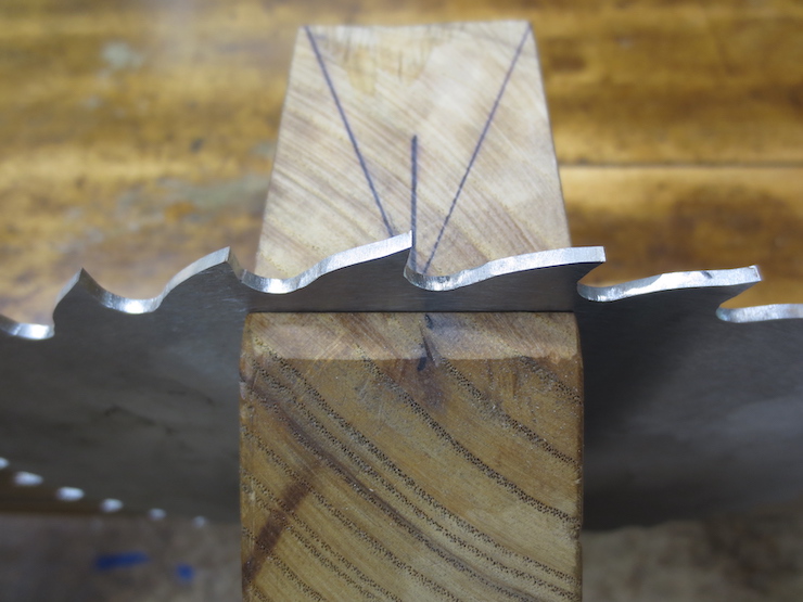
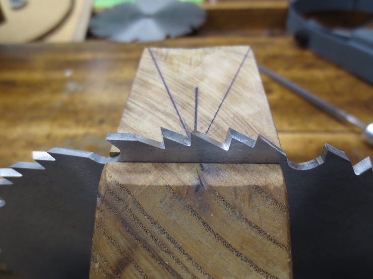
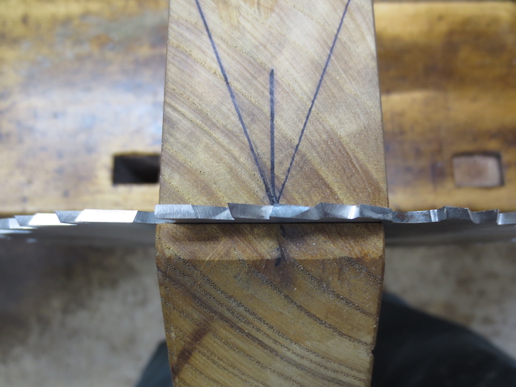
Teeth are filed alternately on both faces until the shiny spots just disappear, leaving the teeth sharp and all at the same height. The raker teeth must be jointed in a different way with each tooth held at top center in the vise. Careful adjustment and a file used with a block of wood joint the cutting edges about 1/64″ lower than the other teeth. Then they too are filed sharp until the jointed spots disappear. The angled teeth slice the wood fibers like little knives while the straight teeth rake out the waste between like little chisels. Since the higher, angled teeth contact the wood first the the fibers are sliced, not torn, leaving a clean surface.
The saw gets reversed in the vise to file alternating teeth.
I rub the file on a file card frequently. I spray a little WD40 on the card which helps the file cut smoother without chattering.
This rip saw is much easier to sharpen. Here, it has been jointed on the tablesaw. You can see the shiny spot that now needs to be filed away.

First the front faces of the teeth are dressed smooth. Here the saw is positioned with a tooth at top center. This way you can angle the file to feel the correct relief angle while filing. The narrow margin visible along the edge of this tooth is where it was jointed. This saw has very little set remaining and that will soon need to be addressed. Less often a saw also needs to be ‘gummed’ which means the gullets between the teeth are filed deeper and the teeth re-shaped as needed.

The tops of the teeth are filed until the shiny part just disappears.

The saw vise can be adjusted for different diameter saws.

The stake and anvil are adjusted with shims so the blade sits flat on the anvil (a large hardened bolt head that has been ground to a slight bevel at its edges). A tooth is positioned to hang over the edge just enough to be bent slightly with a punch driven by a hammer blow.
The center bolt can be moved for different diameter saw blades.
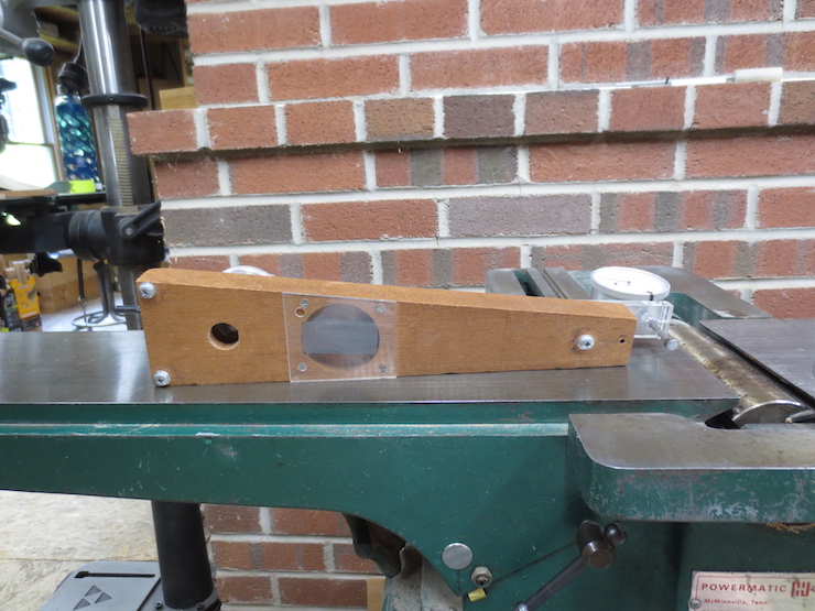
This tool is just a sturdy piece of wood as long as the longest table with three screws on the bottom. A hole at the far end holds a dial indicator which is adjusted to agree with the other three points to define a plane. You can then move the beam around to measure misalignment of the jointer tables. They should be exactly parallel to each other (even when set at different levels). Once you get the machine aligned this step doesn’t need to be repeated. I mention it here because it is important for the machine to be set up well for the precise work needed to make moulds this way.
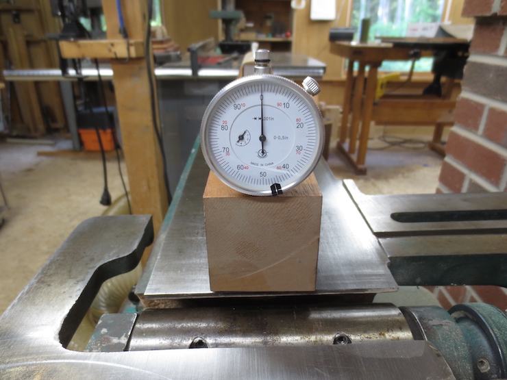
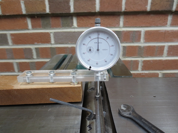
The dial indicator ‘zeroed out’. Assuming the table is flat the tips of the three screws and the tip of the dial indicator together agree to define a plane. The beam can be moved around to check alignment since the spring loaded tip of the indicator will move up or down, measuring differences in thousandths of an inch.

Moving the beam along the in-feed table shows variation from parallel of the out-feed table. Here it registers zero at the front edge of the out-feed table.
Here the indicator registers zero at about the middle of the out-feed table. This is as far as it can go without having a screw drop off the edge. (The pencil mark indicates the location of the two middle ‘feet’). The weight keeps the three screw feet contacting the surface of the in-feed table. By referencing the flatness of the longest table the dial indicator can measure deviation over about half that length.
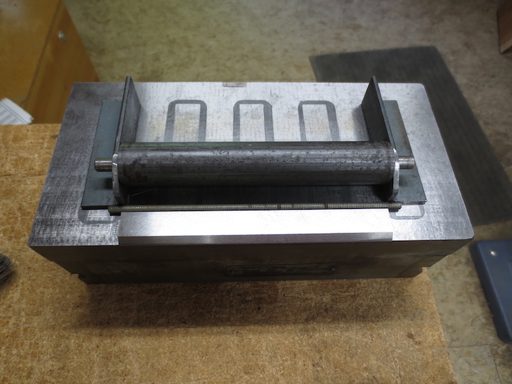
The jointer knife honing jig that relies on this magnetic chuck, mentioned previously. The roller is the core of a defunct printmaking brayer that I found in my scrap box. I carefully drilled the two pieces of angle iron so the roller is held parallel with the flat surface of the magnetic chuck. It is also important that both ends of the roller are set back exactly the same distance from the front ends of the angle irons. These bump up against a piece of rod which in turn rests against the back of the jointer knife being honed. Everything is locked into place when the lever actuates the strong magnets in the chuck. This establishes a honing angle which can later be altered slightly by inserting different sizes of rod. In place above and below is a piece of 3/16″ diameter threaded rod which defines the first (shallowest) honing angle.
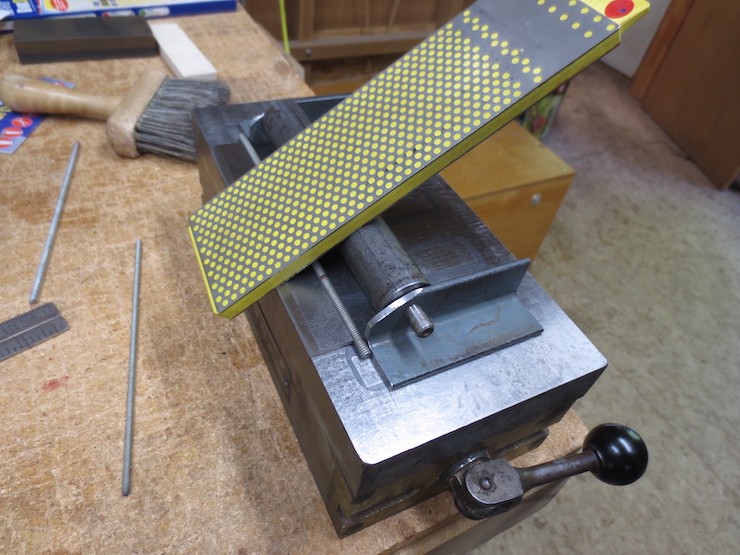
The knife is first honed with a diamond plate.
The results of using the diamond plate.
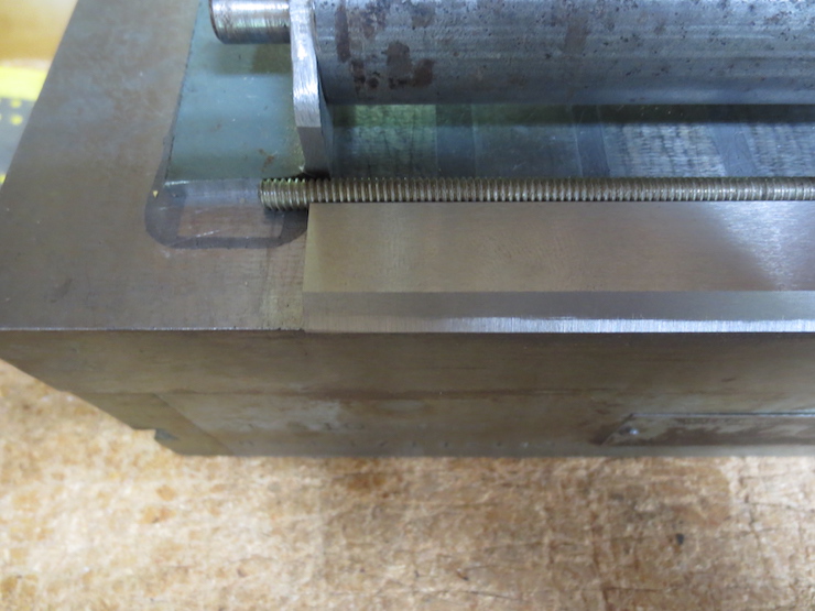
Swinging the lever from right to left de-magnetizes the chuck. This has enabled the first rod to be replaced with a smaller (5/32″diameter) rod. This moves the roller closer to the sharp edge of the knife to establish a slightly steeper angle so this India stone can remove the scratches left by the diamond plate, but only at the very edge.

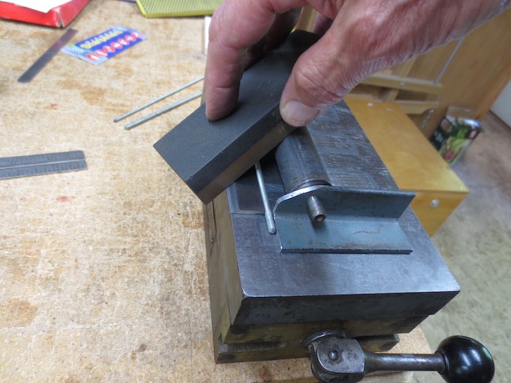
Now an 1/8″ rod makes the angle a little steeper still so this Washita Arkansas stone can polish the edge further.
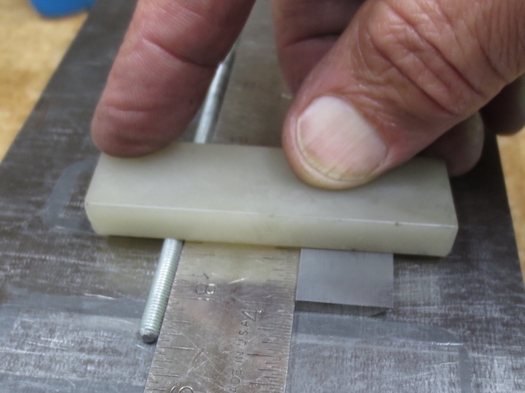
To remove the burr the knife is placed bevel side down. The magnetic base holds the knife, a 1″ wide rule and the 5/32″ rod firmly in place so this Arkansas slip stone can polish a very shallow micro bevel on the flat side of the knife to take off the burr. Few woodworkers will have access to a magnetic chuck. But I thought it deserved mention since it works so well.
A simple home-made dial indicator fixture which I use all the time. Three screws on the bottom establish a plane. A dial indicator mounted at one end measures vertically and one mounted at the other end measures horizontally in thousandths of inches. A magnet helps hold the fixture in place. I often place a weight on the top of the tool for this purpose, too.
The dial indicator is zeroed out on the out-feed table.
Then it can be moved over to set the knives at the same level.
