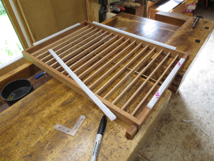
For these moulds both the braces and rub strips are made from polycarbonate sheet.
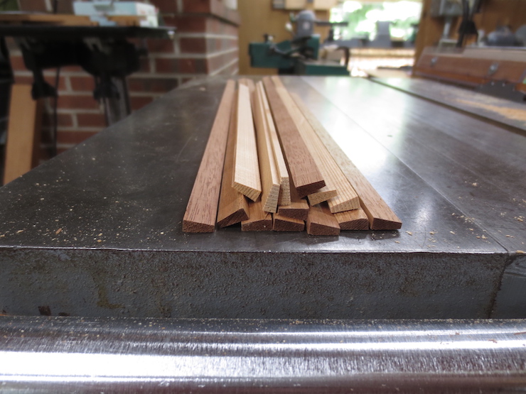
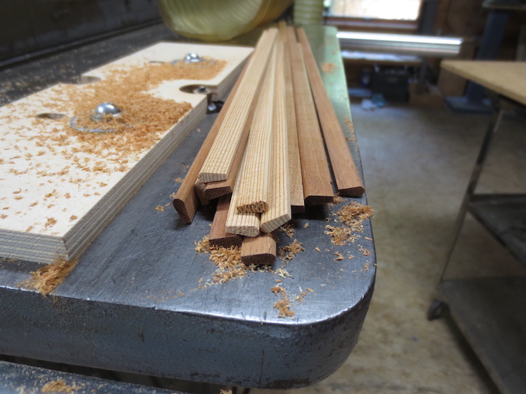
To make rub strips narrow pieces are sawed and cut to length. Like the braces they are made slightly oversized and trimmed off later.
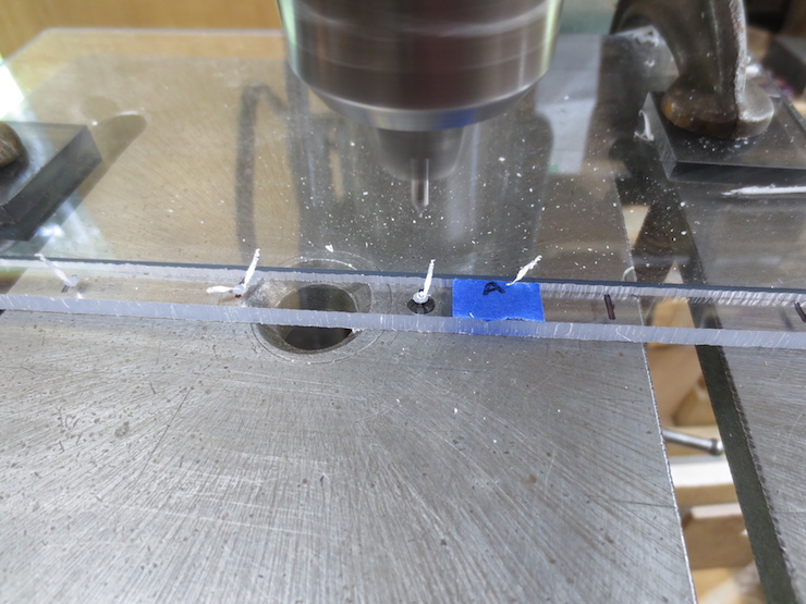
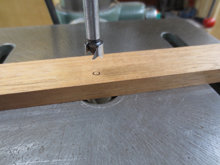
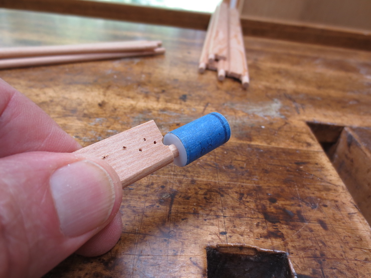
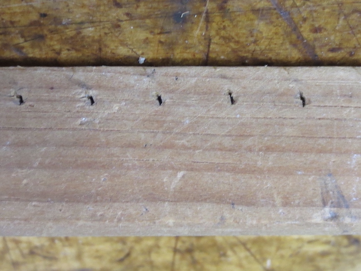
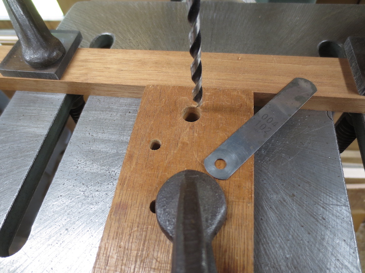
Rub strips are attached with brass escutcheon pins. They are drilled in the same way that the braces were in the last post. First with a #00 center drill…
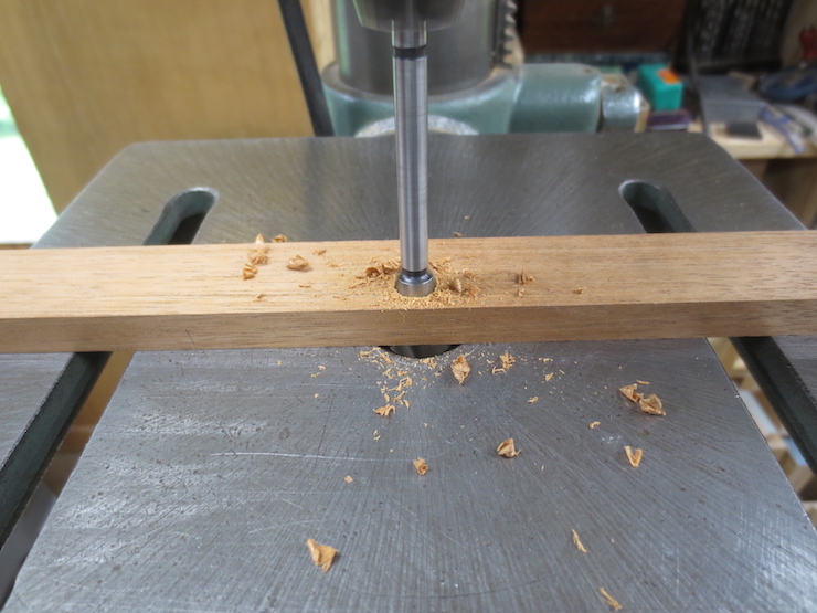
…then with a small number drill.
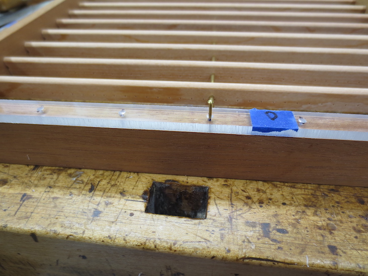
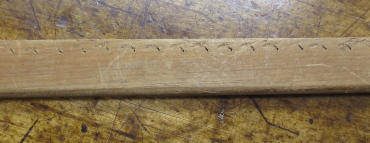
The strips are nailed on with 1/2″ long #18 escutcheon pins.
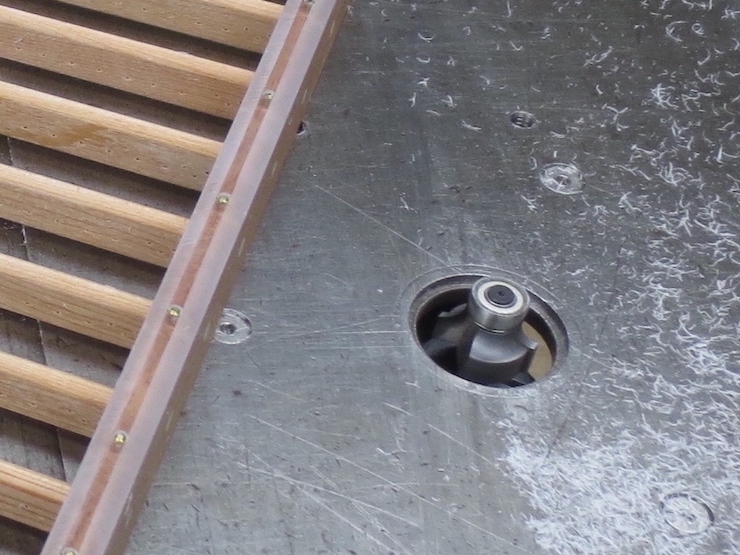
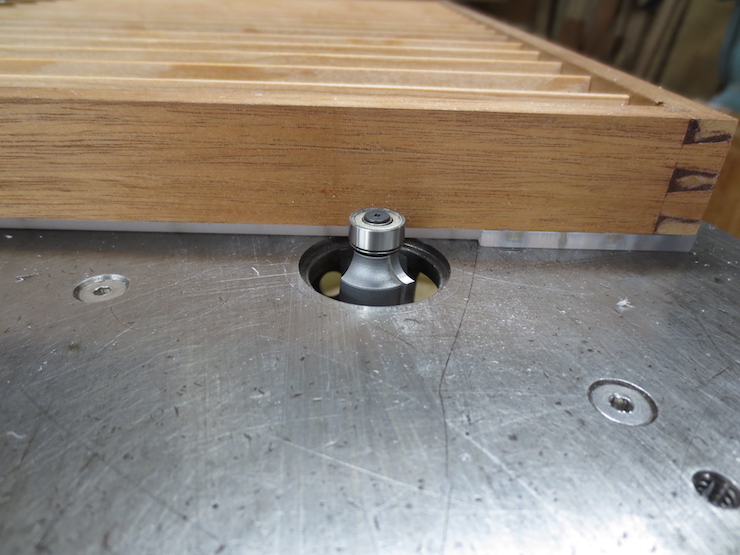
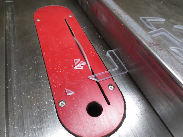
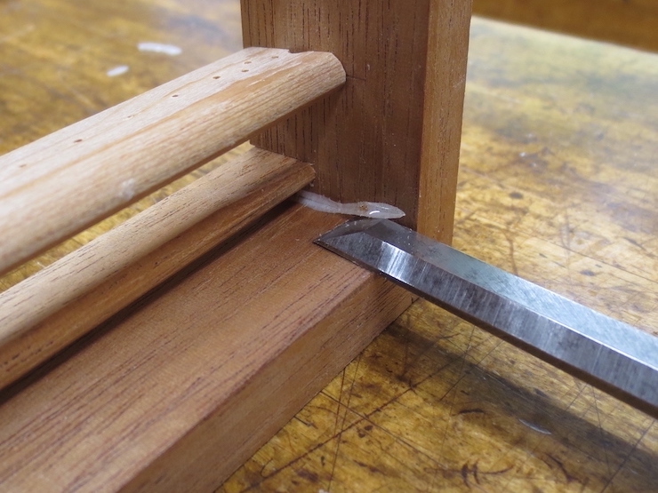
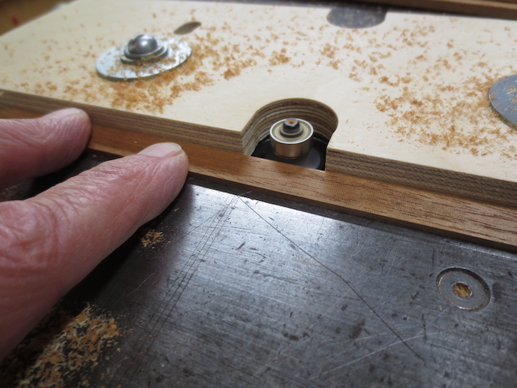
After they are attached the strips are rounded off with a router. This machines off the overhanging material so the ends can be accurately trimmed to fit the braces.
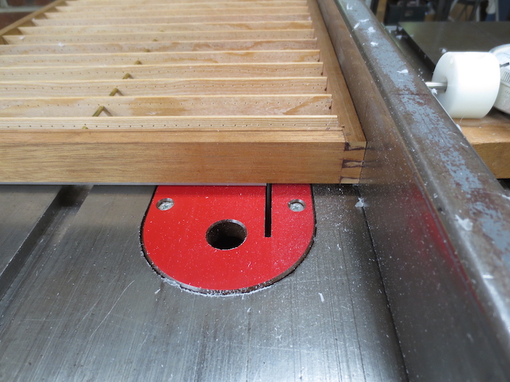
This is how the ends of the rub strips are trimmed square. Once again, the hollow ground planer blade is used.
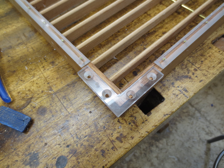
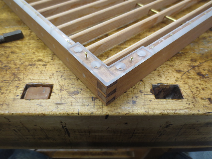
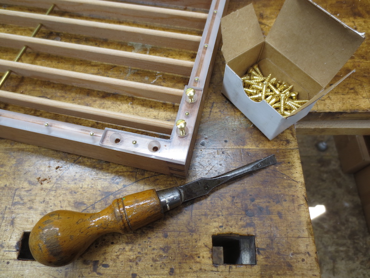
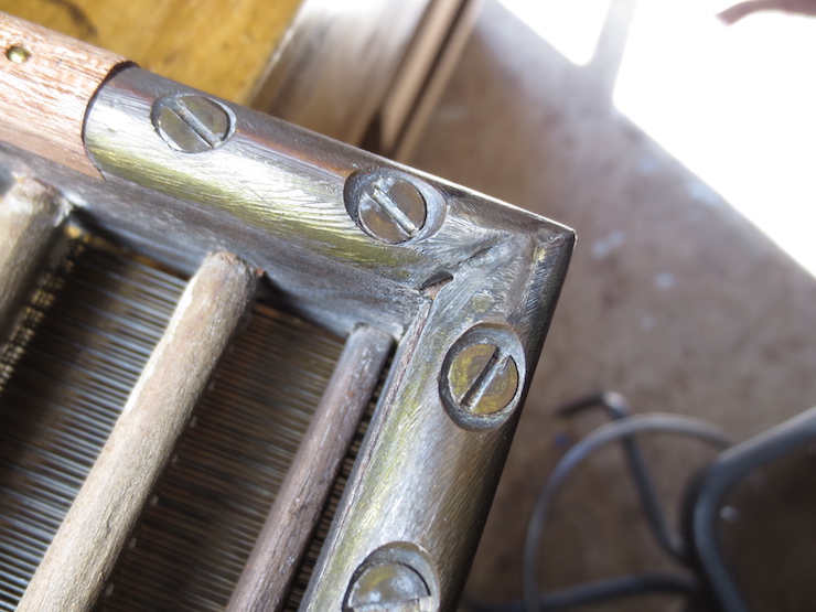
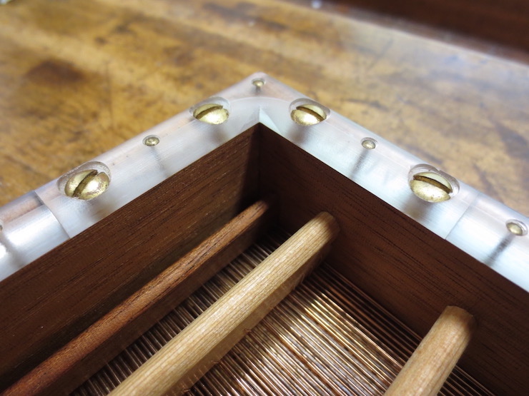
Now the braces can be nailed in place. The heads of the brass pins are driven down into the recesses with a carpenter’s nail set.
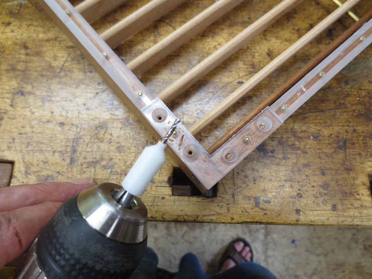
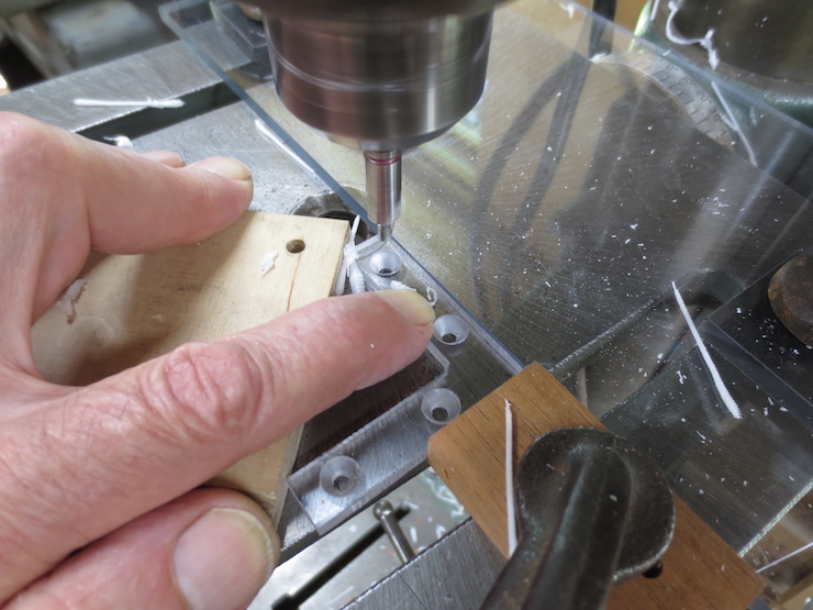
This white plastic guide fits into the countersunk holes to guide the drill so the pilot holes for the screws are centered.
A larger hole is drilled a little way into the wood to accommodate the unthreaded part of the screws.
This tool is just a ‘stop’ to keep the hole from being drilled too deep.
I use these oval head brass screws because I think they look nice though flat head ones would also be fine.
Now the bottoms of the braces are rounded to match the rub strips.
Corner braces strengthen the mould and protect it from shocks. Both rub strips and braces reduce wear on the bottom edges.
The bottom edges of paper moulds are often protected by the addition of corner braces and rub strips. Here is an older style brace made of brass. You can see that this one was made by soldering two pieces together.
The moulds I’m working on for this series of posts have braces and rub strips made of polycarbonate. This is a very tough material. It is used for glazing storm doors and such, shields on machine tools and, lately, for covid shields in stores and supermarkets. Narrow off-cuts (scrap) are usually big enough for making the parts needed for moulds. This plastic can be machined with ordinary woodworking tools. It tends to be very flat and fairly stiff, both good qualities for making moulds.
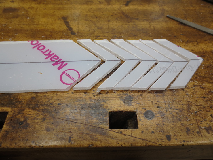
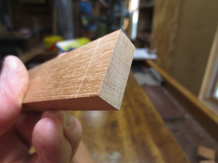
A strip is cut to a suitable width and the center line is marked to show where to stop the cuts when sawing out the L shaped pieces.
The pieces are sawn slightly oversize so their edges will hang off the sides of the mould frame a little. The rough edges will be removed when the bottom of the mould is rounded.
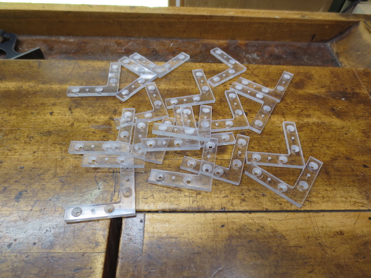
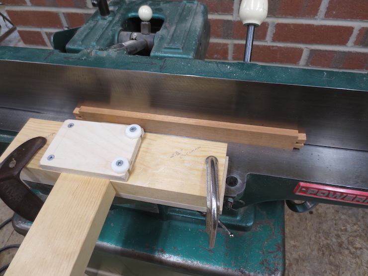
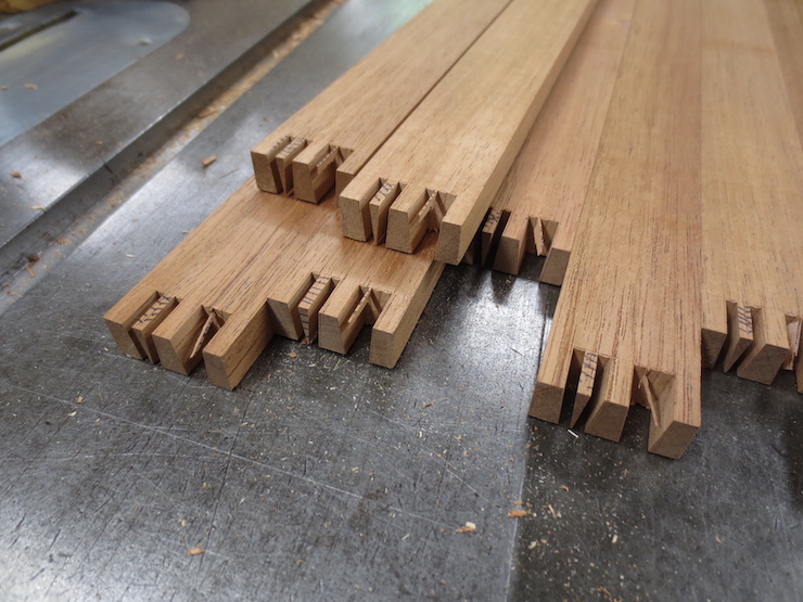
I make enough for several moulds at the same time. The burrs left from sawing need to be filed off before the next step.
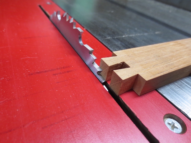
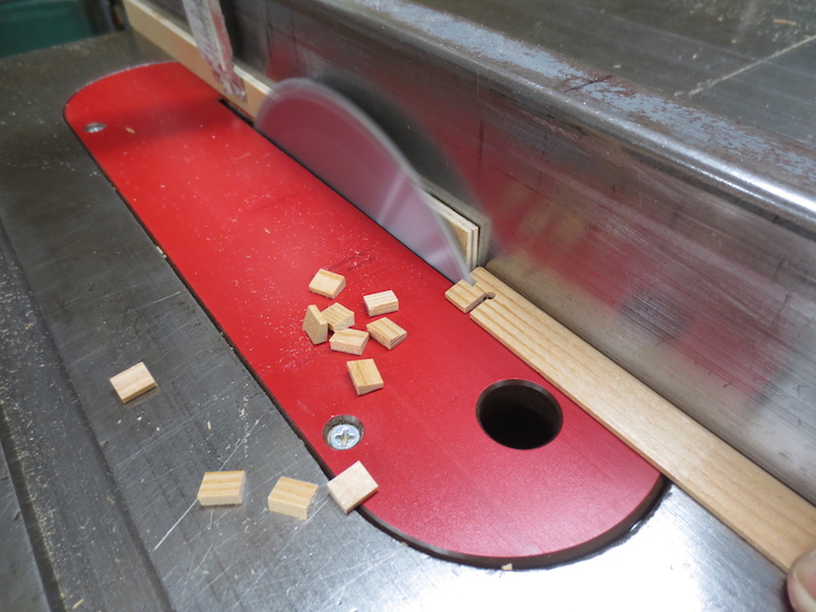
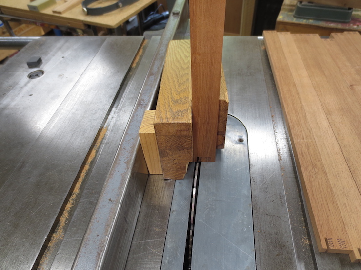
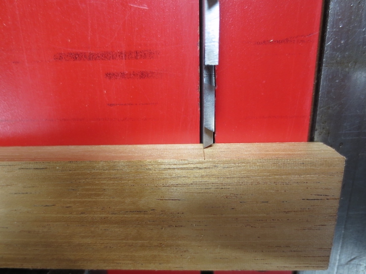
Using the hollow ground planer blade to saw the ends square. These brackets measure two inches on a side.
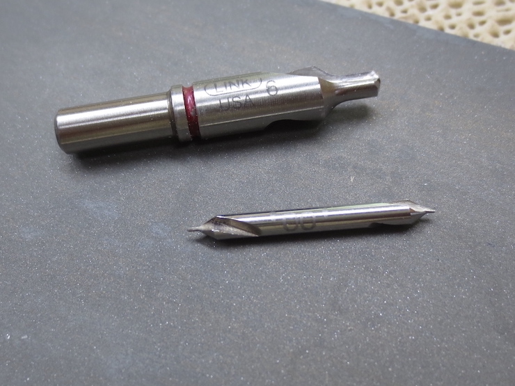
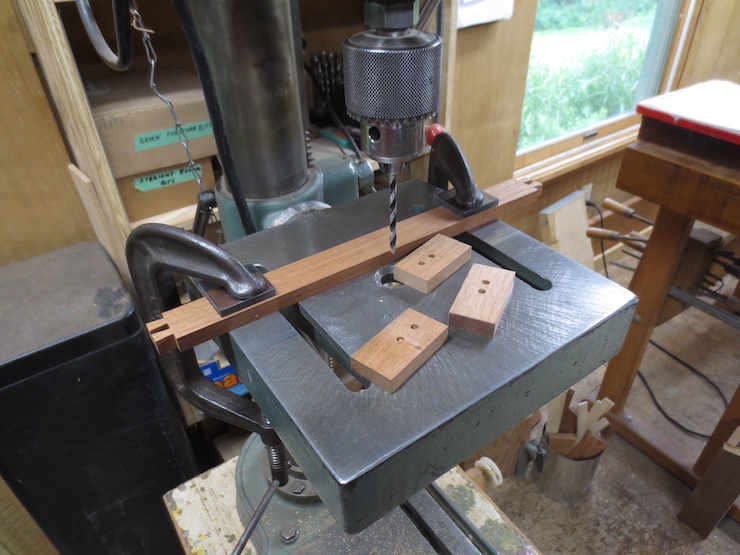
A couple of special tools make things easier. The drill on the top makes a countersunk hole for a standard #6 screw. The #00 center drill on the bottom starts a tiny hole for the #18 escutcheon pins that will be used to tack the brace to the bottom of the mould. The wider part leaves recesses for the head of the escutcheon pins to fit into. Center drills are used by machinists to prepare material to be held between centers on a lathe.
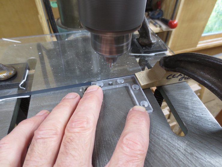
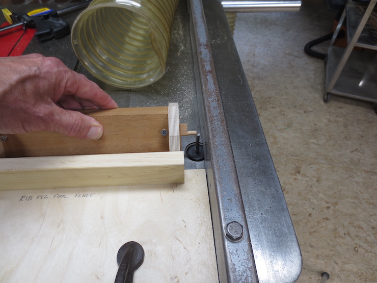
A fence is clamped to the drill press table to keep the holes centered. A stop is set to drill the first hole in all of the parts and then moved to determine the locations of succeeding holes.
These burrs must be removed before moving to the next hole. This can be done by hand using this countersink.
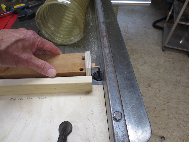
Drilling the last of the four holes. Larger moulds sometimes have larger braces with six holes and screws.
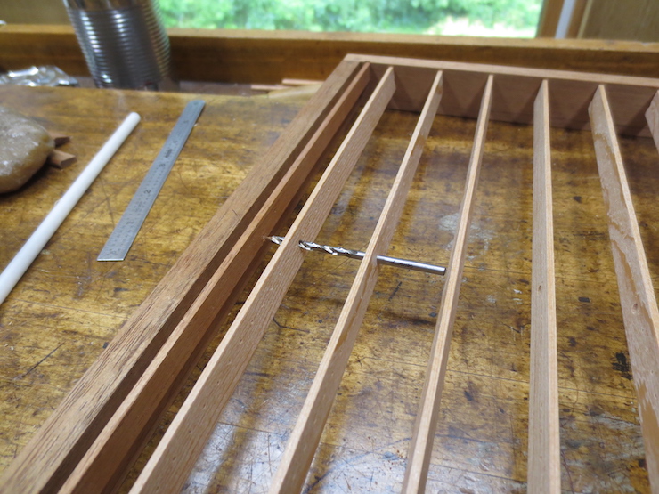
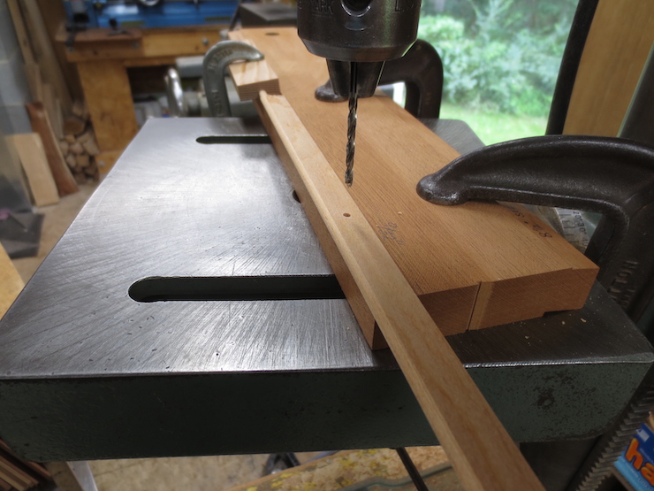
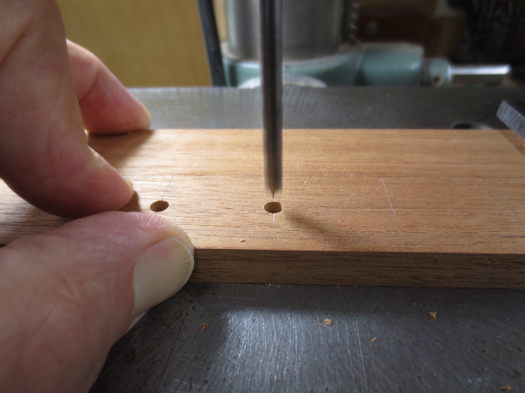
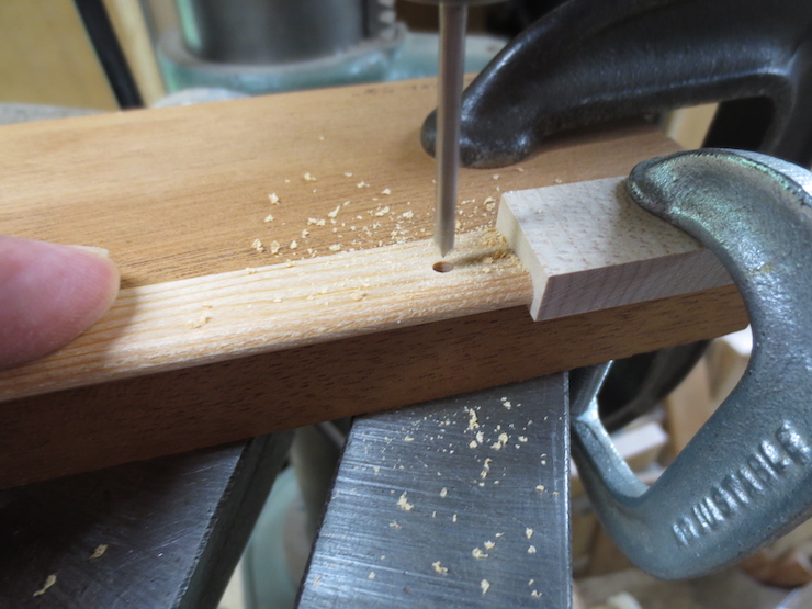
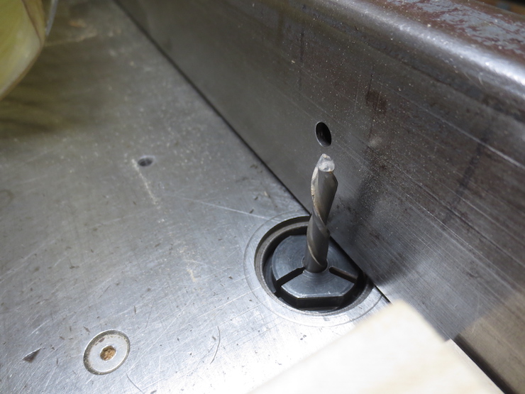
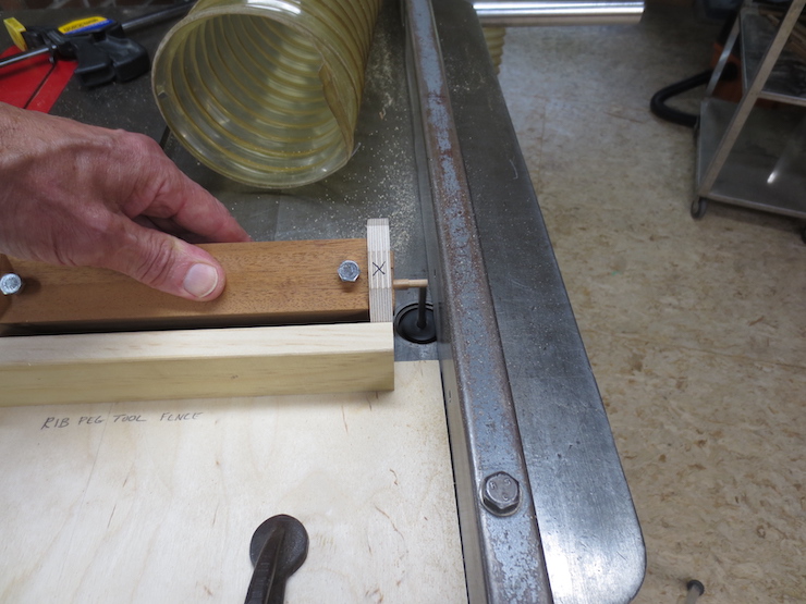
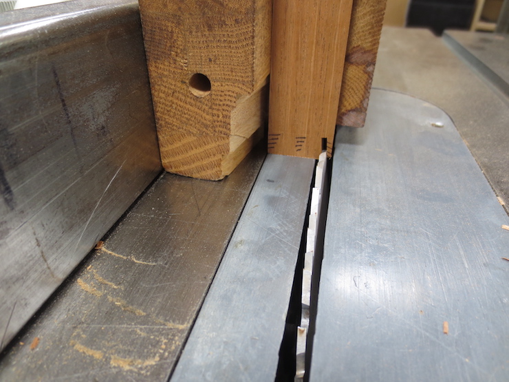
I start drilling for escutcheon pins using the center drill. The pins make it easy to install the braces and, in theory at least, add a bit of grip between the braces and the mould.
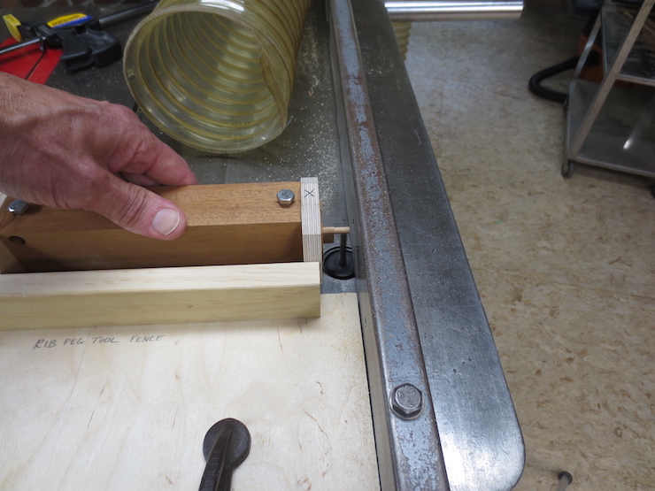
The center drill doesn’t reach all the way through. To drill the rest of the way I choose a number drill that leaves a tight fitting hole to drive the pins through. The tight hole keeps the pins from working out. (Number drills are a series of 60 small drills that range in size from .040″ (#60) to .228″ (#1). )
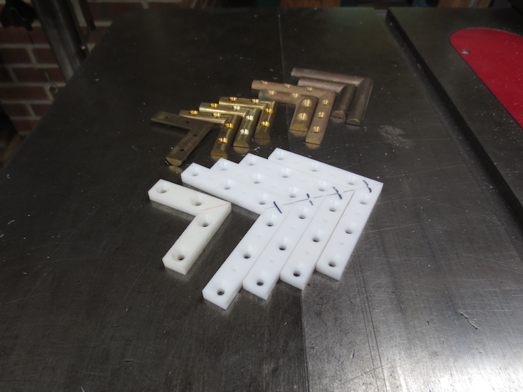
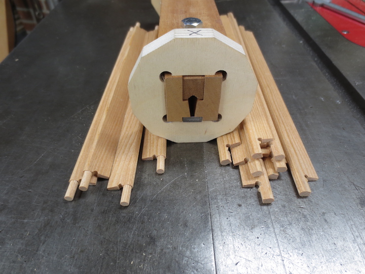
All the braces needed for the five moulds being made.
Many years ago I was inclined to copy traditional moulds more closely. I made patterns and had bronze braces cast for this reason. I believe that many braces on old moulds were castings but I now know that some were made of soldered pieces of half round brass.
In the back are cast bronze braces including one set that are finished and ready for a mould. Making braces this way is a lot of work. The white ones are made of acetal. These are much easier to make, lighter weight and very tough. They were made in the same way as the polycarbonate ones described in this post.
Here is some half round brass that I have recently purchased. At some point I’ll try mitering and soldering this material to make some corner braces.
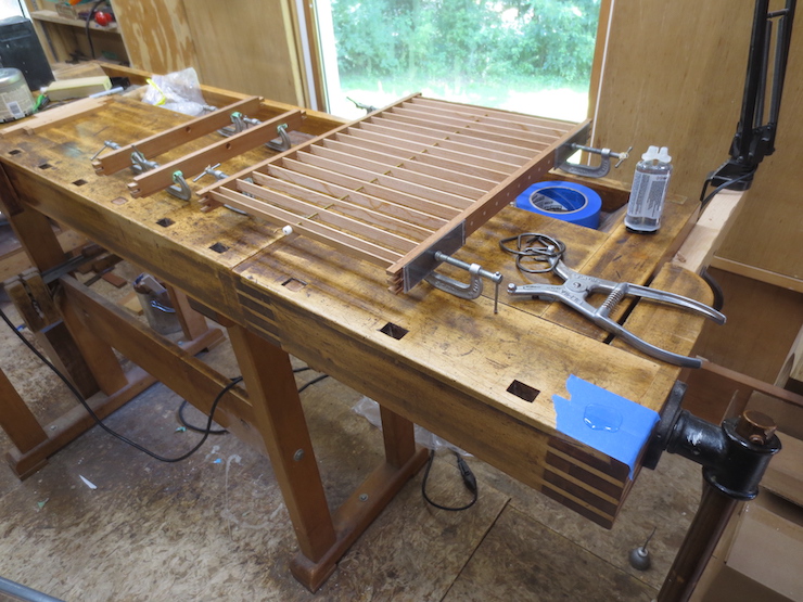
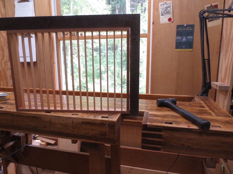
This mould has had epoxy applied to the corner joints and is secured with spring clamps while the glue cures. The dents left by the clamps poking into the wood will be covered by brass sheathing.
Using clamping cauls eliminates the dents for moulds without sheathing. This mould is ready to glue and clamp. At the ready are spring clamps, the clamp spreader and a puddle of epoxy ready to be mixed and applied.
I buy Devcon 2 Ton epoxy at my local hardware store. I mix and apply it with a short piece of 1/16″ brass rod with ends sanded and buffed smooth.
Glue is applied to both parts for every joint.
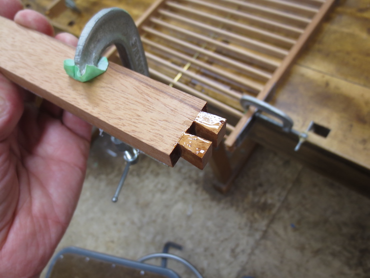
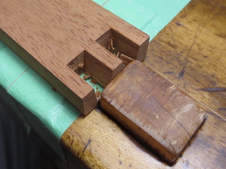
The socket for the brace rod end.
The cauls are made of thin polycarbonate plastic with pieces of sanding belt attached with contact cement. A groove has been cut along each end to engage the points of the spring clamps.
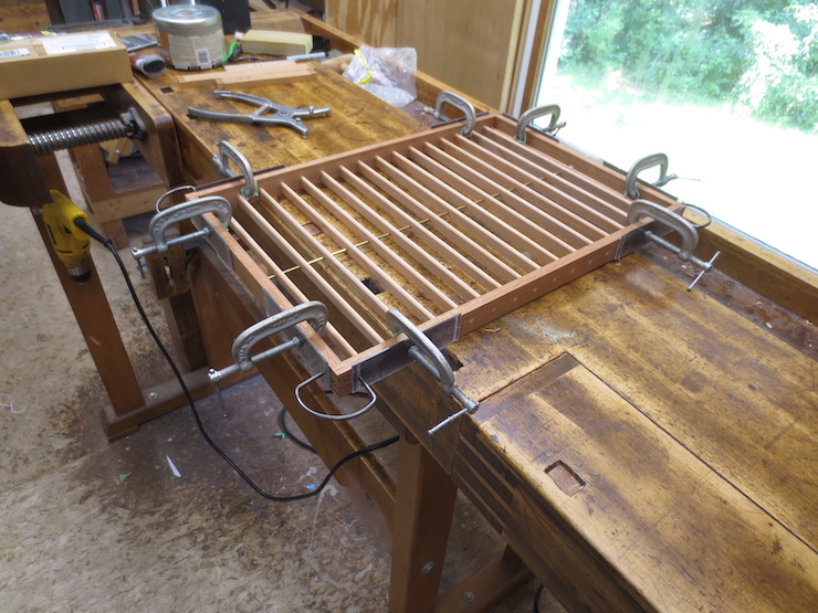
The clamps hold the parts tightly together while the glue cures.
The mould stays in clamps until the next day.
There is always glue squeeze-out to clean up.
Excess epoxy inside a corner.
Epoxy can be pared away with a sharp chisel.
The job is finished with a file.
Squeeze out around the brace rod end is easy to clean off with a chisel.
Applying a little paste wax with a toothbrush after dry-fitting the parts but before gluing helps the excess epoxy come off a little easier.
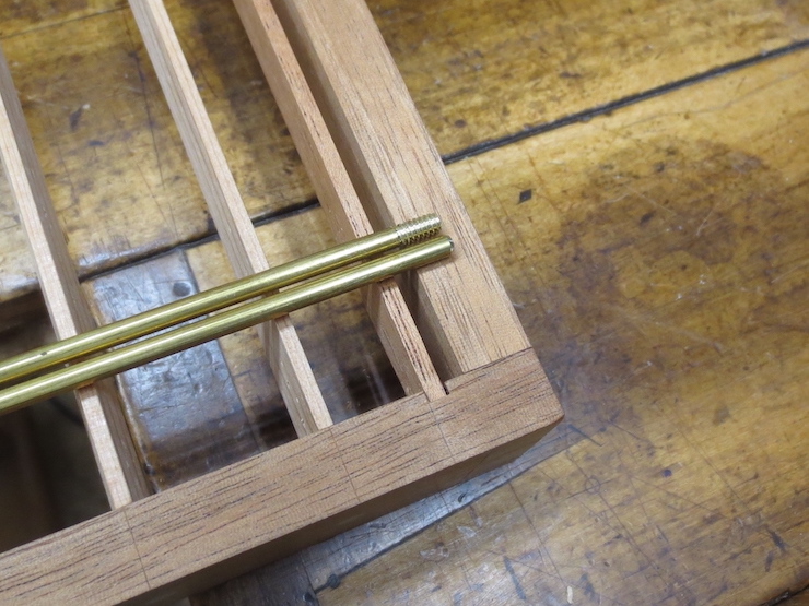
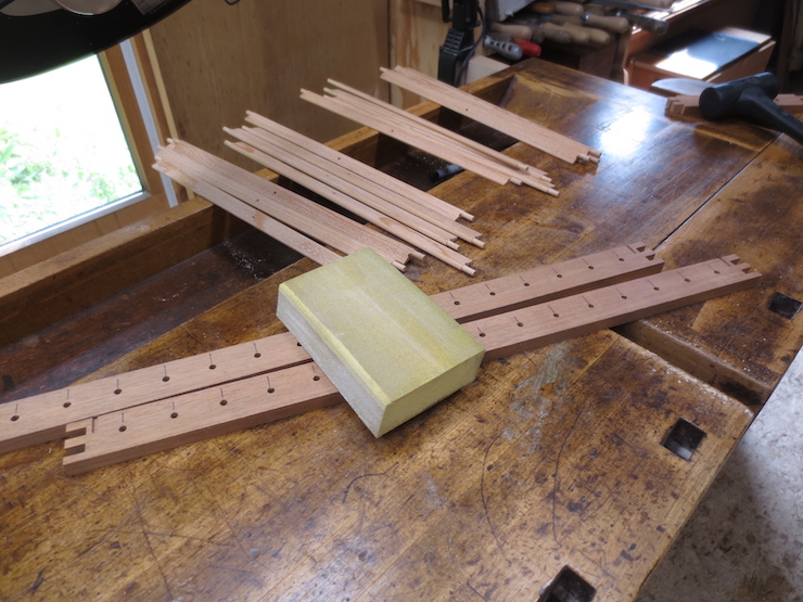
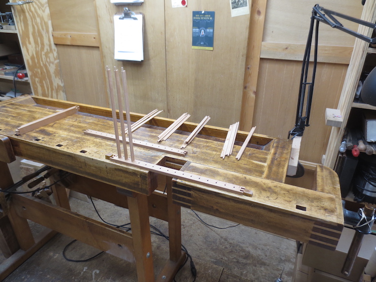
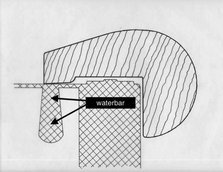
Before the corner joints of a mould are glued one or two brace rods must be fitted. One for smaller moulds, two for larger ones. They will pass through all the ribs and be anchored in the frame at both ends. Waterbars also need to be fitted along the ends of each mould.
The waterbars are really just little ribs and have the function of helping to draw water away to help form a good deckle edge. They are made in much the same way as the regular ribs. I straighten them and cut them to size in only one sequence of steps, unlike the ribs which have been reduced and shaped in two sequences. This might make more sense after reviewing the post on making ribs.
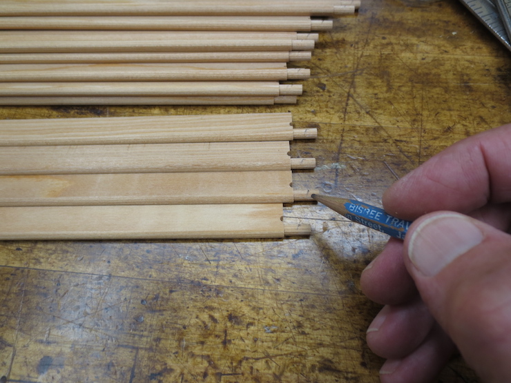
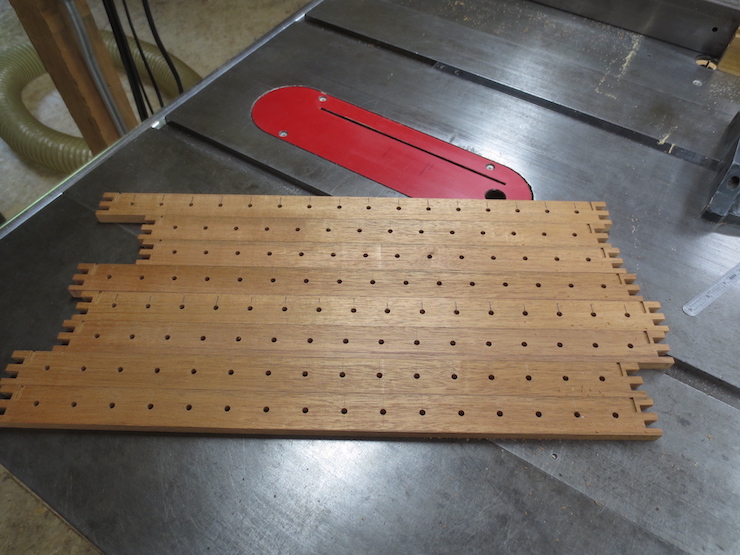
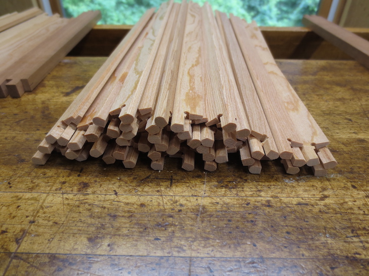
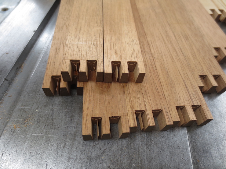
A by-product of roughing the deckle parts to an “L” shape are small strips of wood just right to make waterbars from. The straightest of these scraps were saved to make these waterbars. The lighter colored ones are for the experimental wove mould that is being made completely of Larch.
The bottom edges are rounded just like the ribs were.
These are ready to be cut to length and fitted into notches in the mould frames. They have tapered sides and rounded bottoms like ribs but do not need pegs formed on the ends.
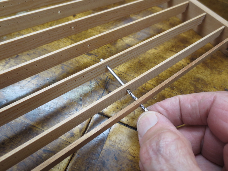
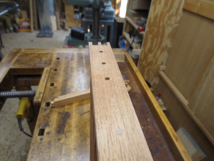
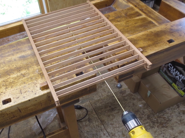
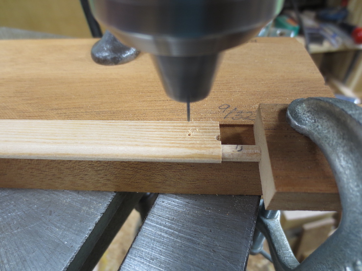
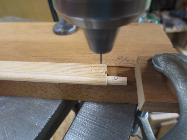
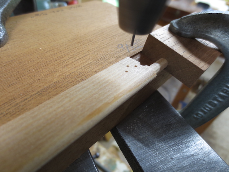
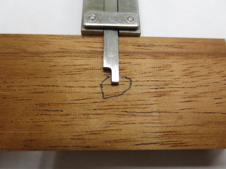
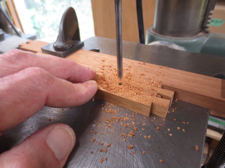
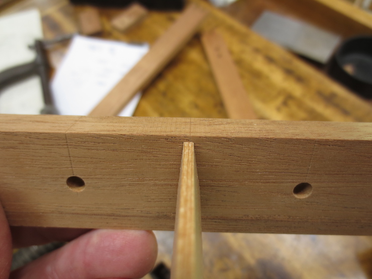
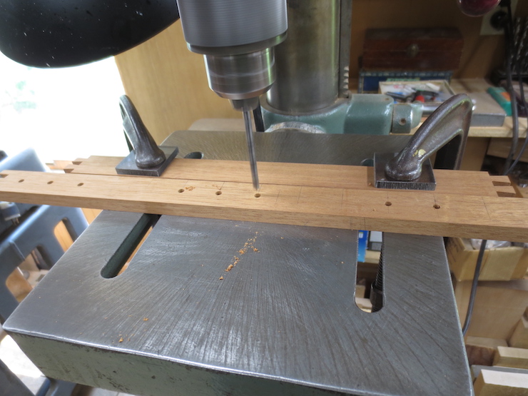
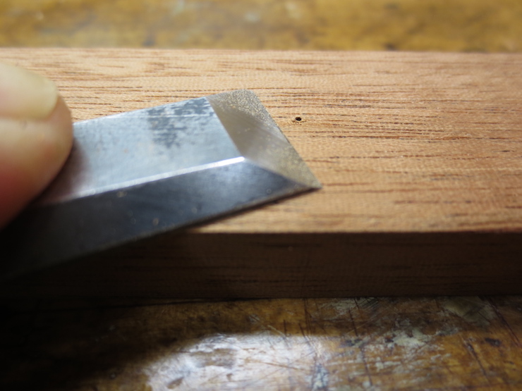
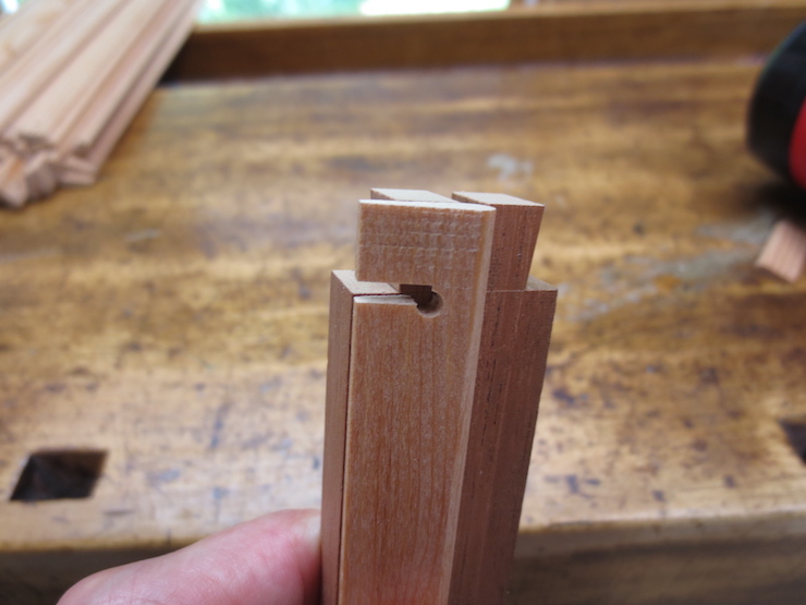
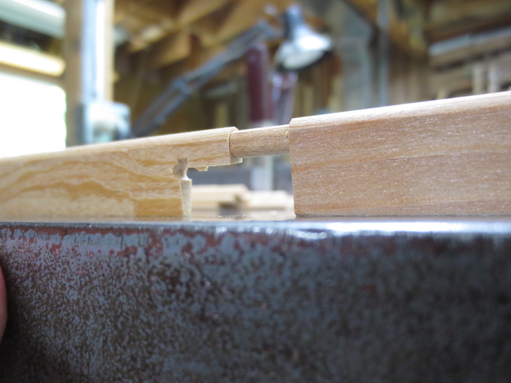
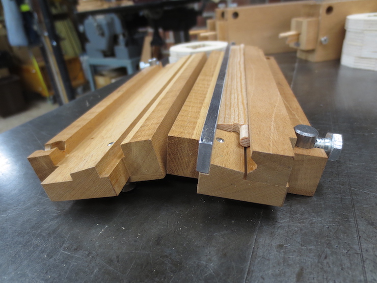
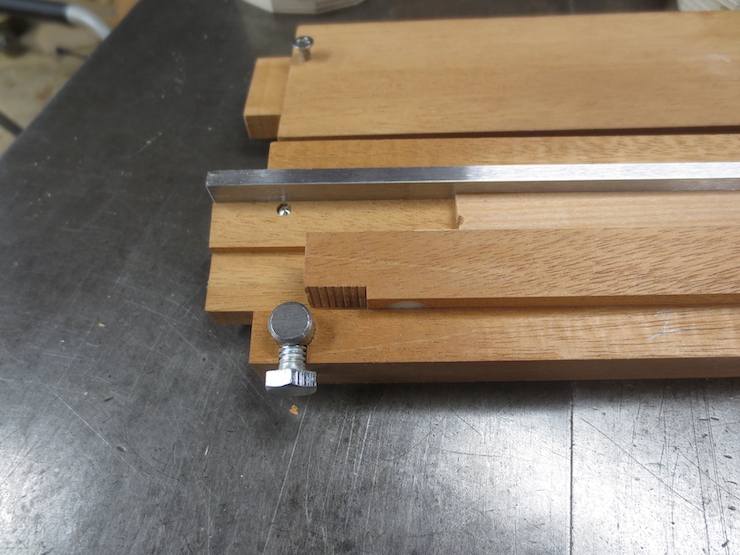
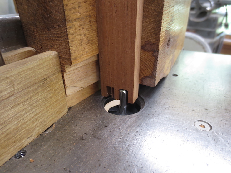
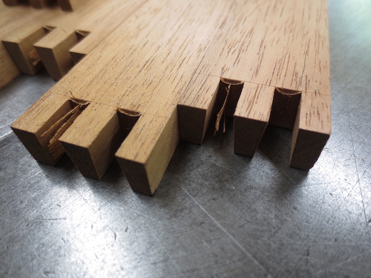
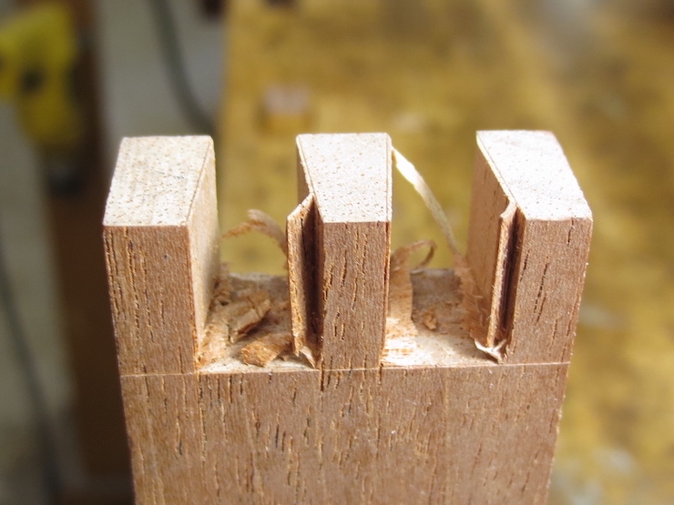
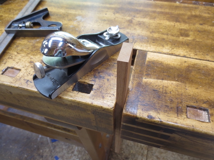
Instead the ends are slimmed down with a block plane to fit into shallow mortises previously routed in the frames. Here a waterbar has been fitted into place and a brad point drill is being used to mark the location of a hole that needs to be drilled for a brace rod.
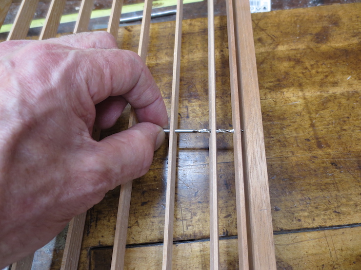
The brad point drill is turned with the fingers until the wings score the wood.
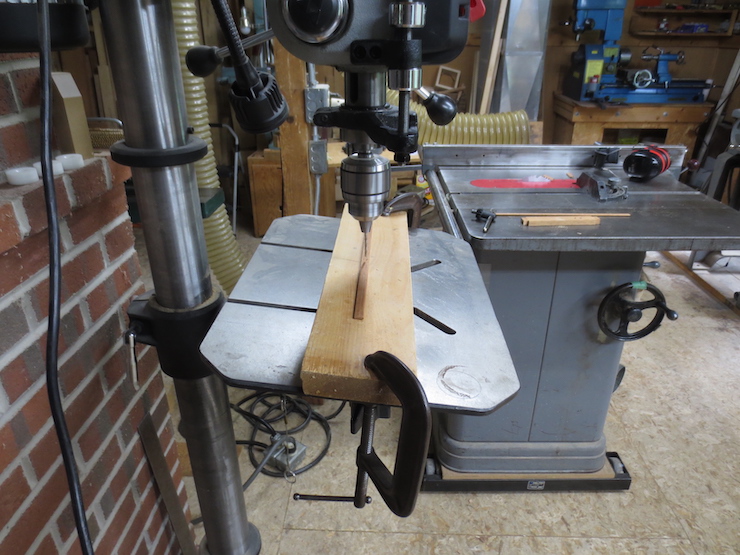
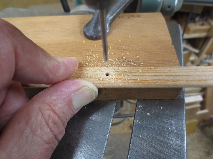
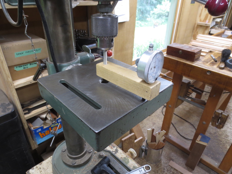
The sides of the waterbars are tapered so the table of this drill press is tilted to drill the hole at an angle. Using the same brad point drill to mark and then to drill is a good idea.
Fitting a Brace Rod
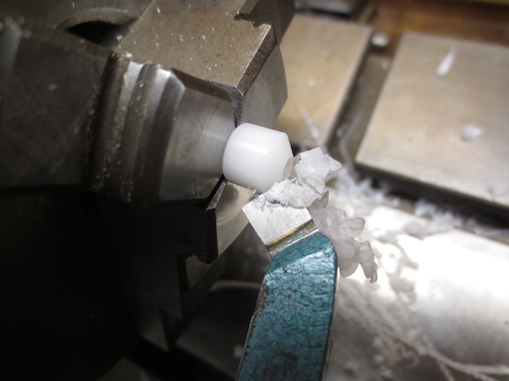
1/8″ diameter brass rods are used to brace the ribs. They are threaded on both ends so larger diameter acetal plastic ends can be screwed on.
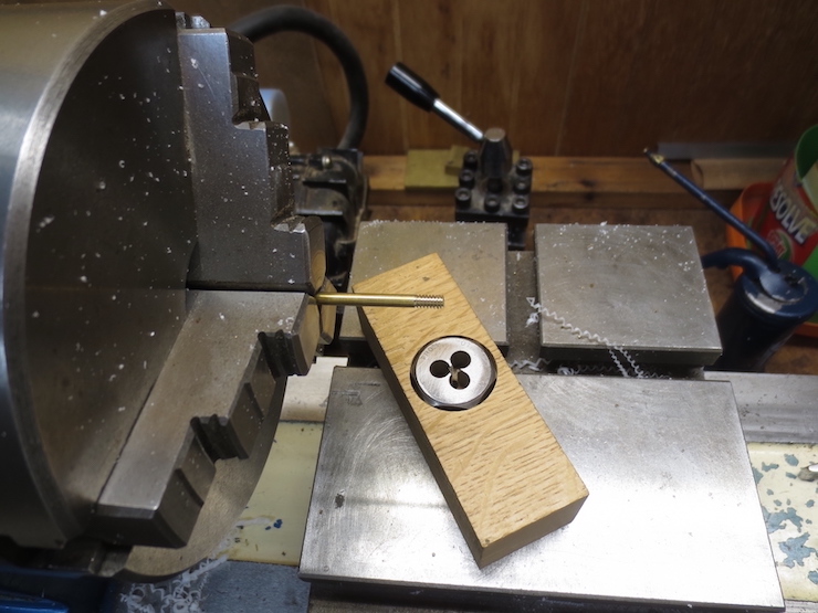
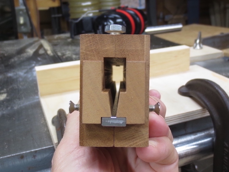
Here, a 6-32NC threading die has been embedded in a block of wood with a 1/8″ diameter guide hole drilled through to the other side. The rod is held in the lathe chuck as the die is turned by hand. The power to the lathe is disconnected.
About 1/4″ of the ends are threaded.
In old moulds these rods are often hammered flat and inserted into slots chiseled into the ends of the mould frame. A small pin at each end anchors them in place. Until recently I glued the ends into same-size holes and then drilled for a 1/16″ diameter pin after the glue was set. This works but is tricky; it’s not easy to ‘hit the target’ and the brass shavings enlarge the hole in the wood as they are carried away by the flutes of the twist drill. And it is easy to break a drill this small. Now I prefer the method described in this post.
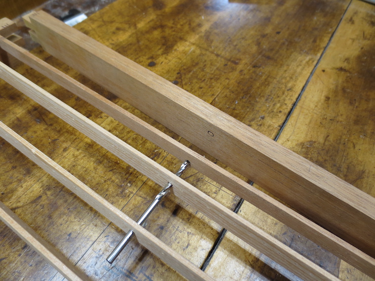
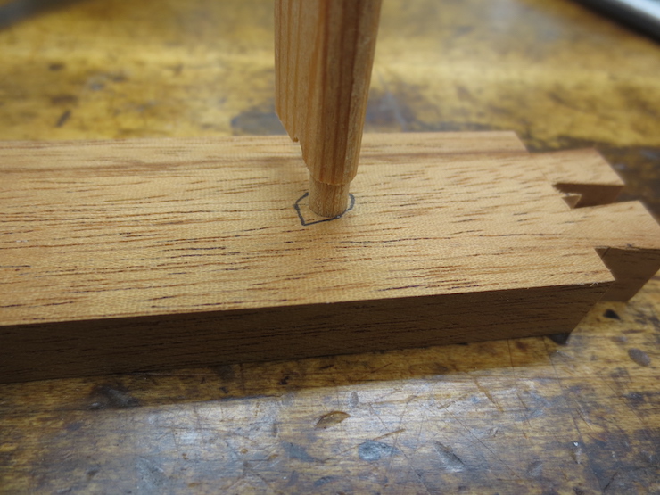
A brad point drill is backed into the holes in the ribs and waterbar in order to mark the place where a hole needs to be drilled into the frame.
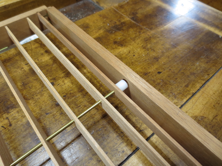
In these moulds the brace rods pass through the waterbars. This is a recent innovation of mine to accommodate the narrow ribs in these small moulds. In larger moulds with deeper ribs (and all other moulds I’ve seen) they are not drilled this way. Usually the waterbars are added after the mould frame is complete. They rest on top of the brace rod(s) and are bound to them with wraps of wire.
The end of the frame is removed to be drilled after the point of the drill has marked it. The inked circle makes the mark easier to see in the photo.
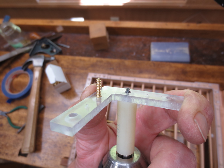
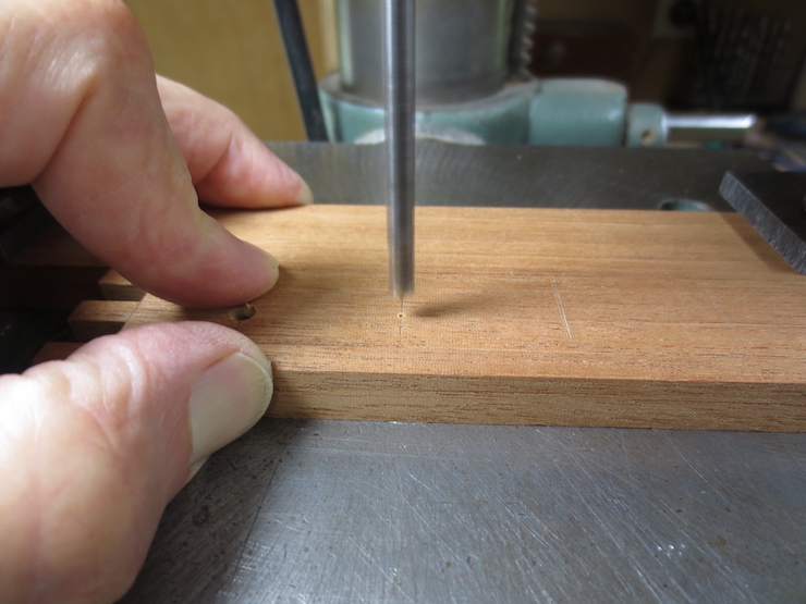
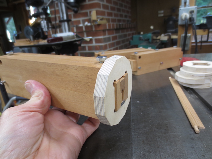
A 3/8″ diameter hole is drilled to fit the acetal plastic cylinders that will be threaded on to the ends of the brace rod. To start the drill I lift the wood up and feel that the point of the drill is in the small hole. (This with the drill press turned off.) Next I move the drill down with the feed handle to push the wood gently down onto the table. Then the motor is switched on to drill the hole.
A forstner bit drills a clean, flat bottomed hole; good for this purpose.
The hole is drilled about 3/4 of the way through.
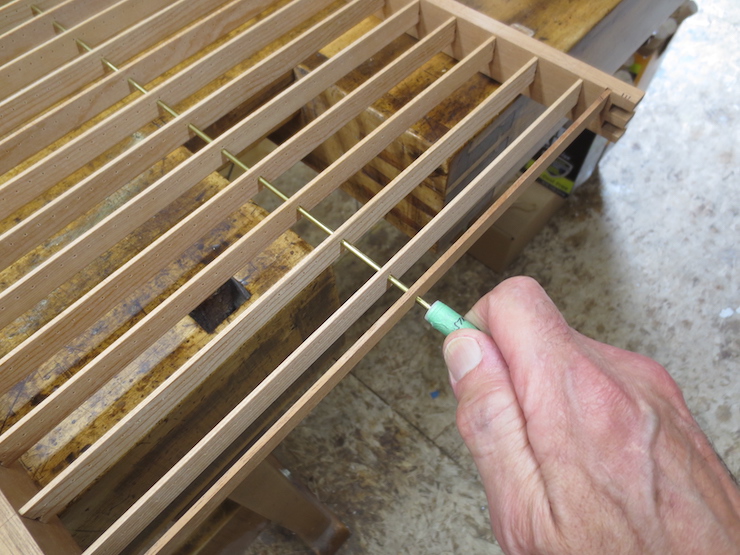
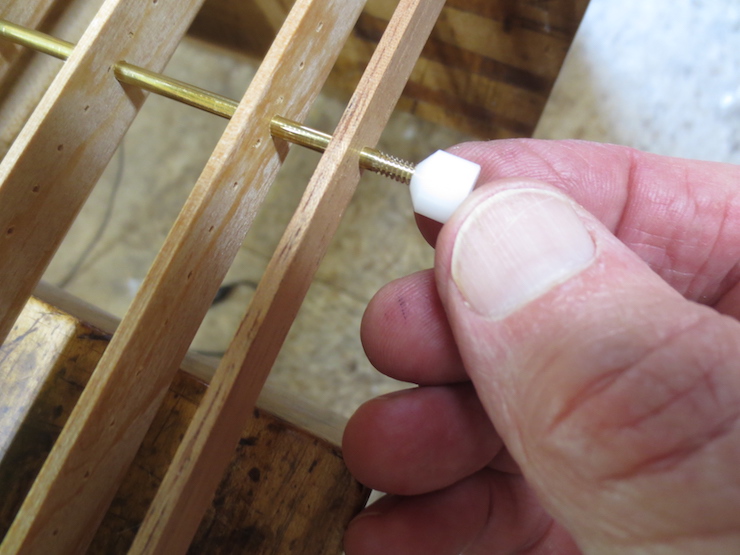
The brace rod is inserted through holes previously drilled in the ribs.
A piece of plastic rod is threaded onto the end of the rod as a sort of wrench. It is used to twist the brace to even it up at the ends.
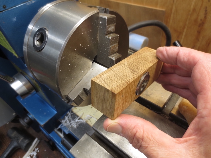
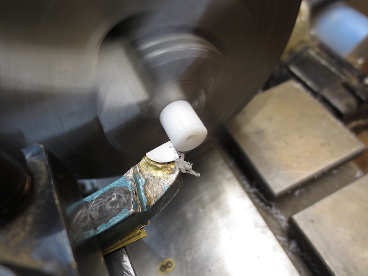
Fittings for the brace rod ends are prepared. Pieces of acetal plastic rod have been cut and surfaced at both ends to about 3/8″ length. Smooth 1/8″ diameter holes have been drilled 1/8″ deep and smaller (#36) holes have been drilled all of the way through and threaded with a 6-32 NC tap. Here the outside diameter is being reduced to fit into the 3/8″ hole drilled into the wooden frame. (The acetal rod is manufactured slightly oversized to allow for machining.) For this operation the fittings are threaded onto a scrap piece of threaded brace rod that has been chucked into the lathe.
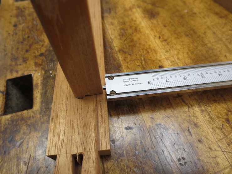
The inner end of each is beveled. The waterbar will rest against this end. The length of the fitting and the depth of the hole in the frame are calculated so the waterbar will end up being held at the right distance from the frame.
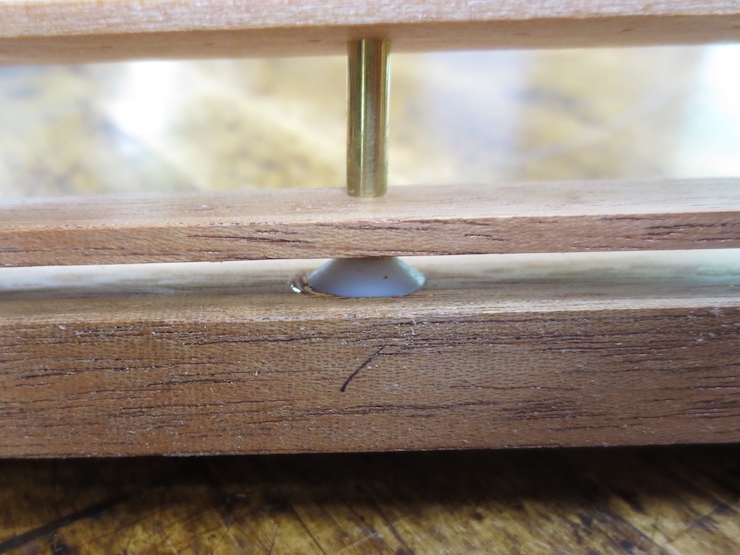
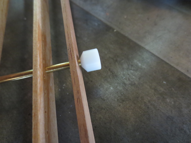
A fitting is threaded onto the brace rod at both ends.
The plastic fitting has a couple of advantages. It strongly secures the brace rod to the frame and holds the waterbar away from the inside of the frame. Waterbars can slide along the brace rods and often shift out of place.
The ends can be adjusted by screwing or unscrewing them a little to make the overall length exactly right so the ends of the frame won’t be bowed in or out.
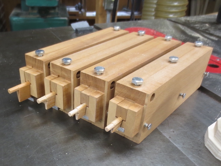
The frame joints and the brace rod ends are ready to be glued with epoxy. After the epoxy has set a 1/16″ diameter hole will be drilled down through the wood and plastic (slightly to one side to just miss the brass rod). A brass pin is then tapped into the hole to make the connection even more secure.
The first step in putting a mould together involves only the ribs and the four pieces of the frame. Other parts; a brass brace rod and extra ribs called waterbars will follow.
You may recall that one edge of each frame piece was intentionally left rough. This bottom edge is now smoothed by a single pass over the jointer.
Compressing the pegs by twisting them into a sized hole smooths out the facets left from the twelve sided rib peg tool. This also makes the ribs easier to fit into the holes in the sides of the mould.
Ribs are lightly sanded mainly to remove the little bits of wood that are left from drilling all the sewing holes.
The inside surfaces of the frame are also lightly sanded.
One end of each rib is inserted into a hole.
The penciled numbers are used to keep the ribs in the proper order.
Four ribs to go.
After all of the ribs are fitted in one side the whole assembly is carefully turned around so the free ends can be started into holes on the second side. One at a time, ribs are gently twisted back and forth while pushing them down. All will end up about halfway into the holes at each end. In this photo only the first and last rib (not visible here) have been moved down.
This just shows how the ribs move down as they are re-positioned. Three ribs have been moved down partway into the holes of the opposite frame piece.
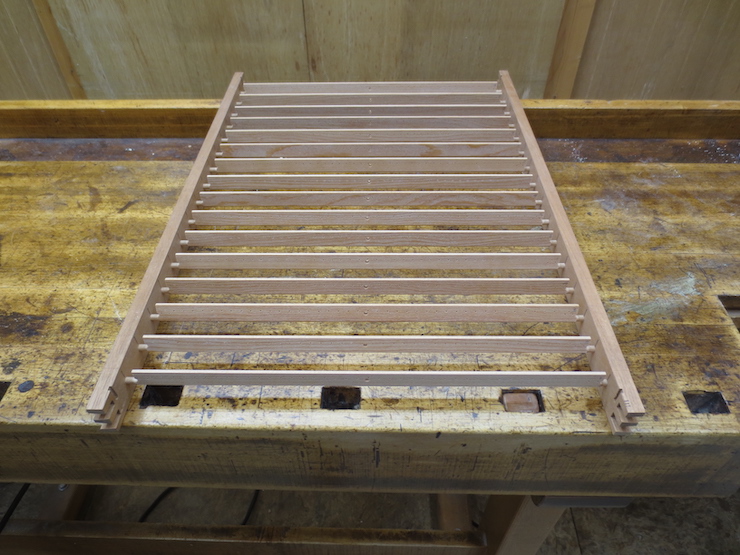
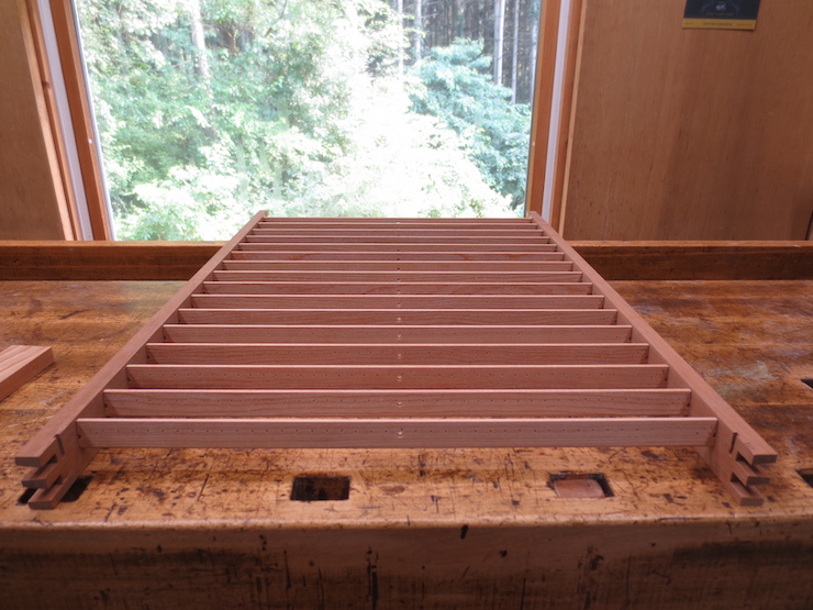
When this step is completed the mould looks like this. The rib pegs are all about halfway into their holes.
Now the frame must be pushed in from both sides. This is done gradually as the sides are gently tapped together in small steps. Care is taken to tap evenly across the length of the frame, keeping the sides parallel. I turn the mould around each time so the sides get tapped from both sides equally.
After each stage of tapping all of the ribs are turned a bit in their holes. This is important. Here the top five ribs have been ‘flipped’ down a little by my thumbs running down the sides. If the mould is assembled without doing this the ribs can become locked in; turned at odd angles. It can become difficult to straighten them and there is even a chance of breaking a rib.
When the pegs are all the way in their ends will be flush with the outside of the mould. Now they are aligned with the scribed marks on top. Both ends are rotated at the same time to make a rib stand nearly straight up; then each end can be individually nudged into position.
The narrow top surfaces should be centered on the scribed lines.
Now the ribs are completely inserted and aligned.
The holes drilled to receive the brass brace rod now line up perfectly.
The ends of the mould can be fitted in place.
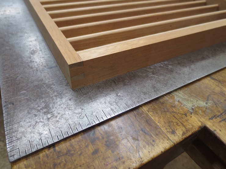
The mould frame should be square, or very nearly so. This is the cumulative result of the care taken to make all of the pieces, ribs and frame, as straight as possible, with ends cut perfectly square; and of being certain to drill the rib peg holes into the frame at exactly 90 degrees.
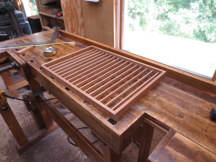
This batch turned out very well!
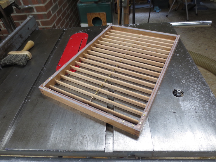
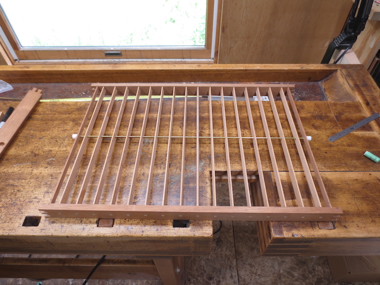
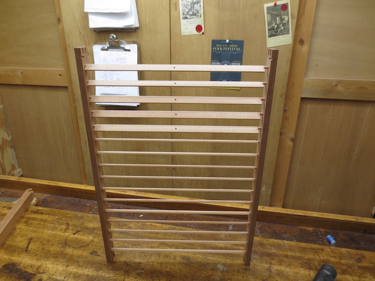
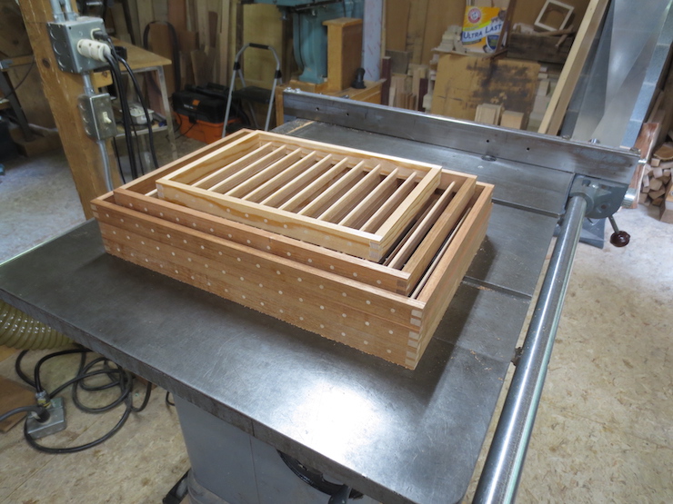
Five assembled moulds, ready to be fitted with brace rods and waterbars.
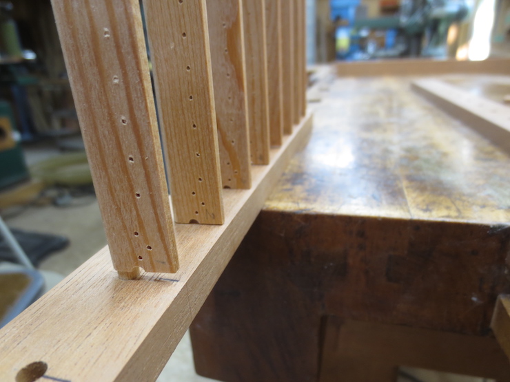
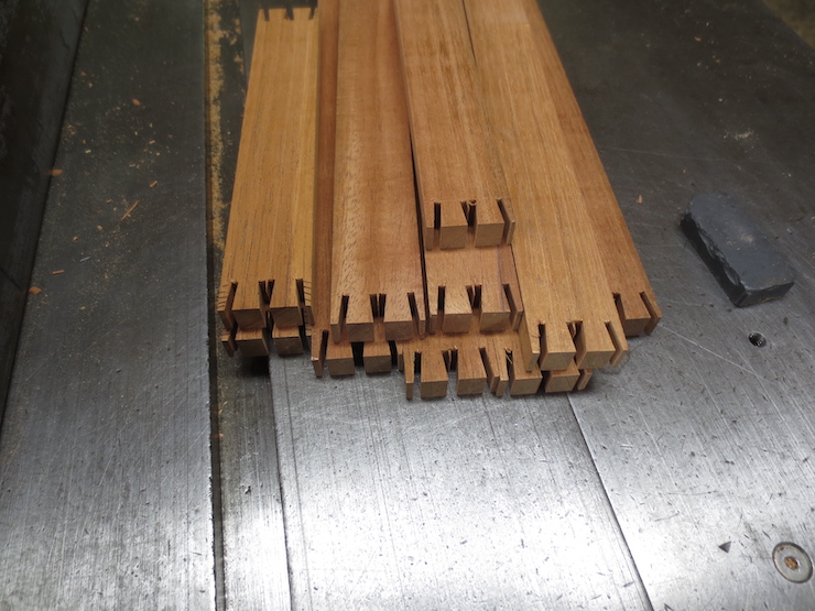
The ribs have been shaped, cut to length and have had pegs formed on their ends. Now each must be drilled for a brace rod and then for sewing holes. The brace rod keeps the ribs lined up and helps them work together for added strength. A row of very small evenly spaced sewing holes are made along the thin upper edge of each rib. These sewing holes must be drilled ahead before a mould is assembled. Later, a single sewing wire will follow a spiral path through all the holes in each rib. Between each pair of sewing holes it will pass up and over the chain wires to attach the wire facing to the mould.
The ribs are all marked on one end. While they are being drilled and later assembled in the mould they must be kept in this orientation with (in this case) the mark always being on the right.
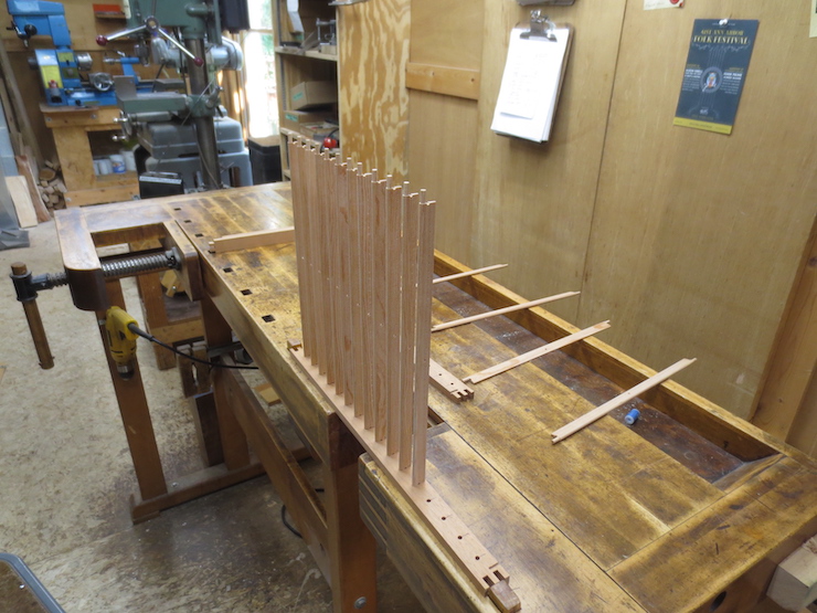
Skipping ahead a few steps shows why this is important. Using care to orient the ribs and holding them against fixed stops while drilling insures that the brace holes line up. In this photo the holes are already there; the drill is the best way I’ve found to insert the brass brace rod.
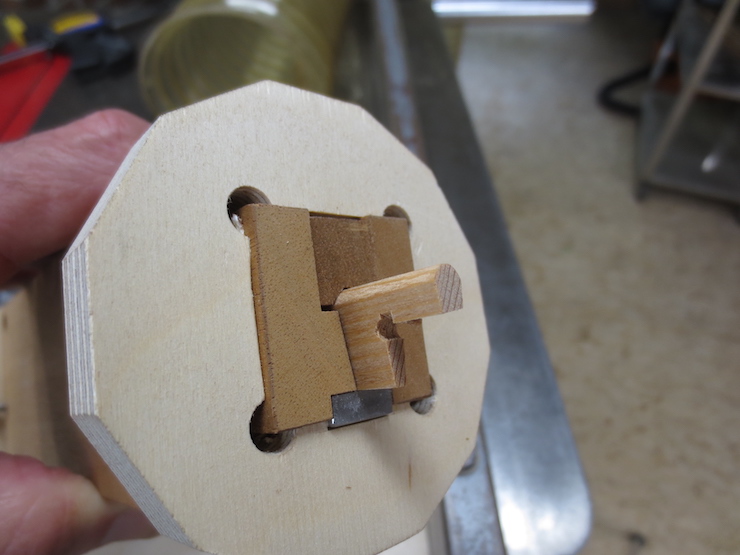
This base has slanted faces so the ribs will stand up straight in the mould after assembly. At the top of the slanted surface is an edge that the ribs are pushed up against; a ‘fence’ that spaces the hole a precise distance from the top edge of the rib.
A stop is fixed at the left to push the ribs against while an 1/8″ brace hole is drilled in the middle of each. Larger moulds often have two brace rods.
Each rib is held in place on the slanted surface of the base and against the stop while a clean hole is made with a brad point drill.
Another view of the drilling set-up.
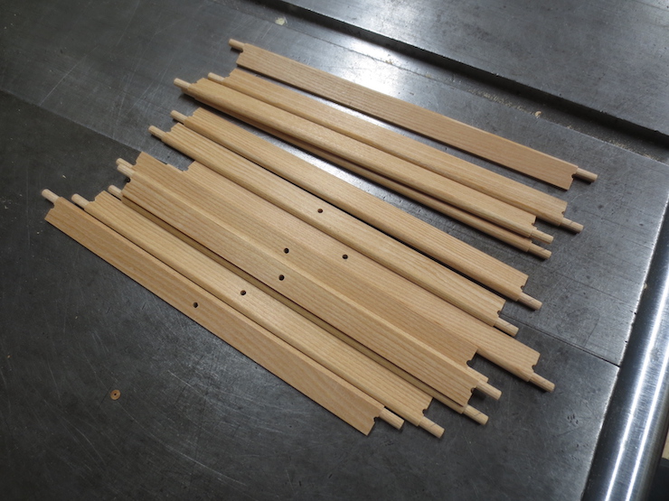
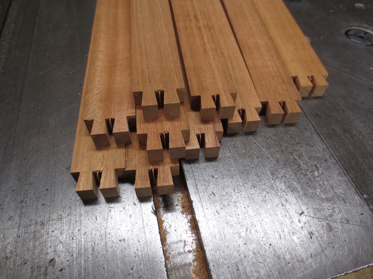
Ribs for a mould. A few still need to be drilled for the brace rod.
Sewing holes are drilled next.
A #60 twist drill is used. The largest wire that I use for sewing is .013″ diameter (for sewing down wove backing) and these .040″ diameter (1mm) holes have proved to be plenty large.
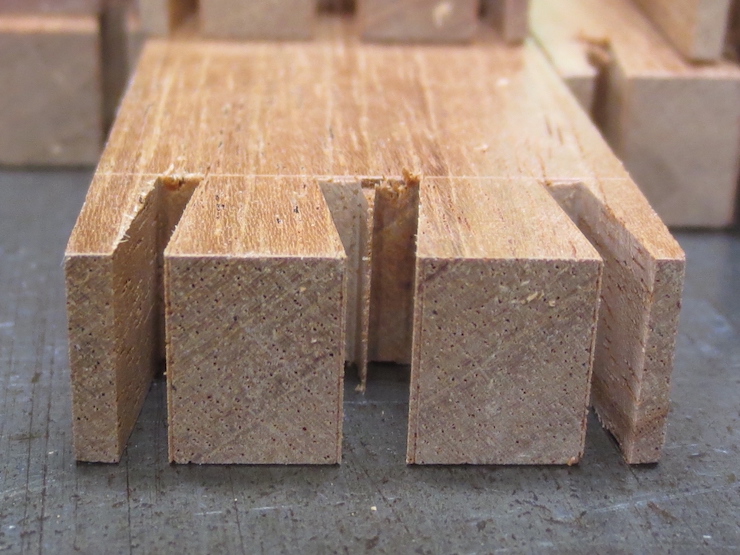
The ribs are given an identical cluster of three holes at both ends. Stitches at the ends of the ribs will be closely spaced; a stitch every other space followed by one each for the last three spaces.
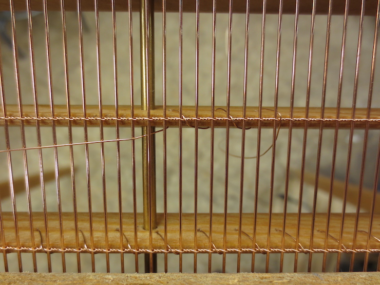
Holes drilled in the ribs of this laid mould have regulated the spacing of the stitches. Along a rib stitches fall between every pair of sewing holes, crossing over a pair of chain wires and between a pair of laid wires. From rib to rib the stitches are staggered so they won’t line up along the laid wires. Both features are pre-determined by the way the holes were drilled in the ribs before assembly. If you look closely you can see where the sewing wires pass through the holes in the ribs, about halfway between stitches.
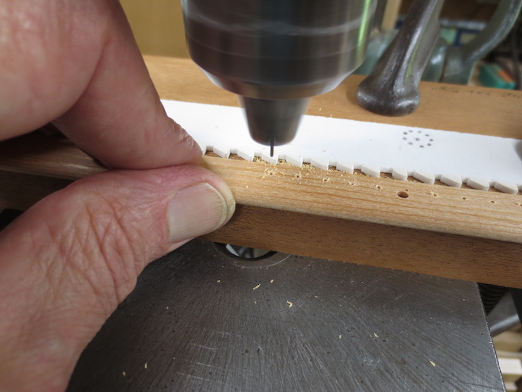
I space the sewing holes for laid moulds at a stitch for every six laid wires. A serrated rack is made for each configuration of laid facing. Above, preparing to cut teeth on a strip of inexpensive, easy to work Sintra plastic. To get the proper spacing a completed laid facing is laid on top and marks are drawn by pushing the pen point down between the wires, every sixth space.
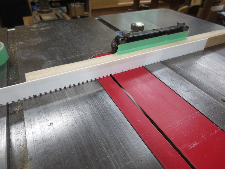
Notches are cut on the tablesaw with the hollow ground blade.
One side of each notch is chiseled away to make teeth, like saw teeth. Once it is finished a strip can be used to make any number of laid moulds that share the same wire spacing.
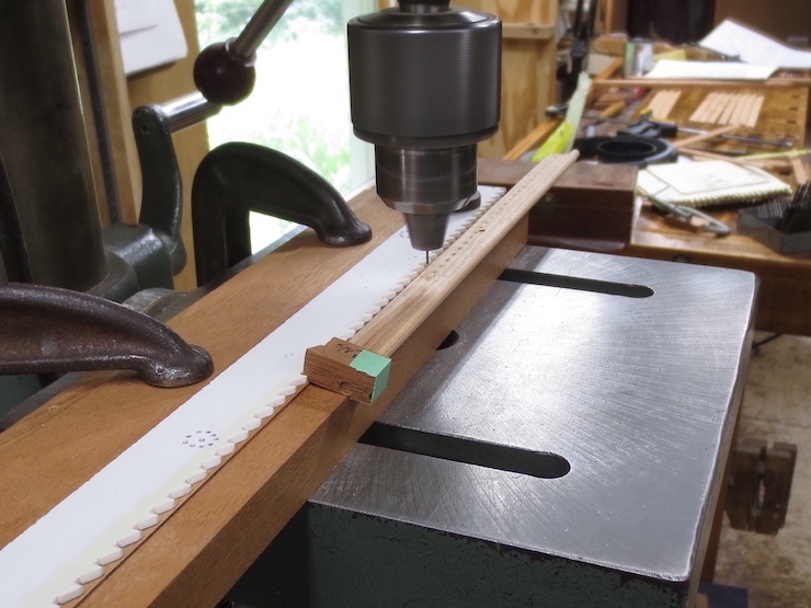
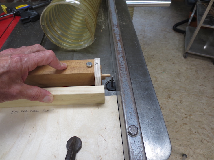
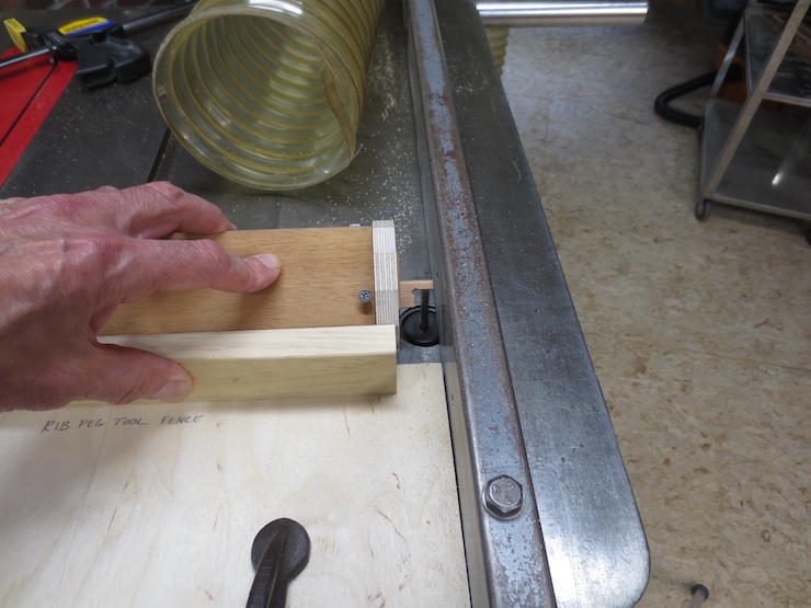
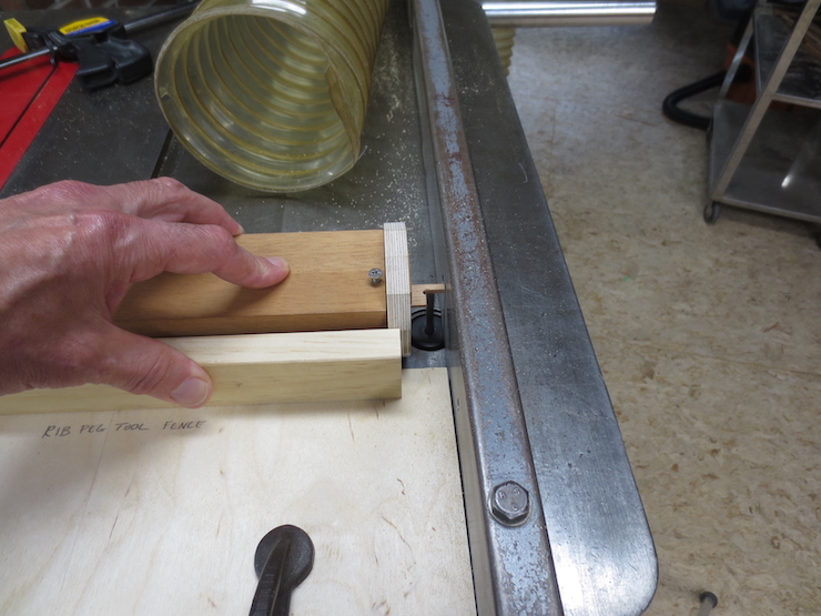
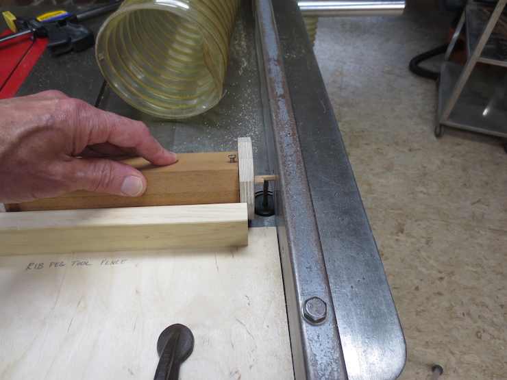
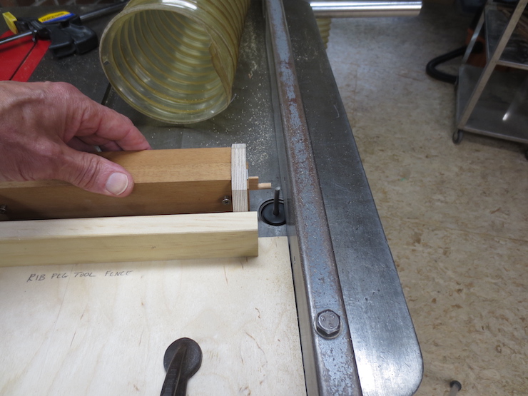
The serrated strip is clamped on top of the base block. A little block (a ‘pawl’) fits over the rib peg to engage the strip. The pawl has a slanted face that clicks in and out of the spaces between the teeth. The rib can be rapidly re-positioned, moving from left to right as sewing holes are drilled at the proper spacing. Holes should be close to the top edge of the ribs so the sewing wire won’t need to be excessively long.
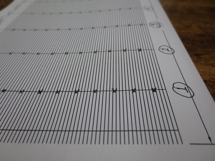
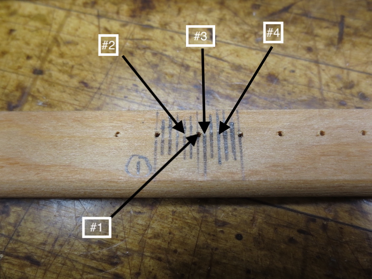
The holes must not be made in the same position on all of the ribs. If stitches pass between the same two laid wires on adjacent ribs it can create a depressed channel in the wires that may show in the paper. This drawing shows a system that helps the stitches skip around without creating an obvious pattern. This random-seeming pattern repeats and every fourth rib is drilled the same.
This laid mould has 14 ribs. I have separated them into four piles and numbered them #1,#2,#3 and #4. All ribs in each pile are drilled the same according to the pattern.
To do this, I drill a test rib (using the pawl and serrated fence) and label it #1. Lines are drawn to divide the spaces between holes into sixths. Each of the #1 ribs is now drilled using this first set-up, creating a row of evenly spaced holes along its entire length . (I’m making four moulds with the same laid wire spacing so all of the #1 ribs for all of these moulds are drilled at the same time, in this case about 16 ribs). Before drilling the #2 ribs the serrated strip is shifted slightly. Using this test rib as a gauge the drill will be set at the mark indicated by the #2 arrow, two increments to the left of the #1 hole. Then all the #2 ribs are drilled, each along its full length between the three-hole cluster at each end. Still following the pattern shown in the drawing the serrated strip is shifted three spaces to the right before drilling all of the #3 ribs. Finally, the strip is shifted two more spaces to the right before drilling the #4 ribs. I don’t know if mould makers would have done this in the past. Perhaps they would just drill (or pierce) the sewing holes by eye to an approximate spacing.
For a different approach see “Post #60 An Alternate Sewing Method.”
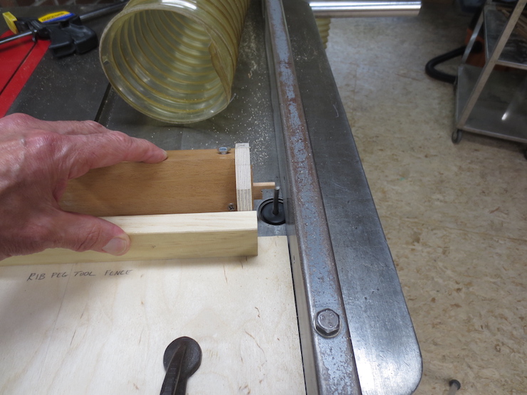
The slanted teeth allow the pawl to climb out and away from one tooth and click back against the next tooth as the rib is pushed along. After each incremental re-positioning with the left hand the right hand advances the feed lever of the drill press to make one hole. Each cycle takes about one second. The drill press is set to spin the drill at a high speed so the chuck and drill can be jammed down quickly after each advance of the rib.
One of each ( #1 through #4) ribs showing the variation in hole spacing. The ribs are placed in the mould in order; 1,2,3,4,1,2,3,4,…
Sewing Holes for Wove Moulds
The sewing holes for my wove moulds follow a simple 1,2,3 diagonal pattern and are spaced to put a stitch between each third pair of laid backing wires. This can be seen in the photo where a wove backing is in the process of being stitched to the ribs. The backing wires will provide a support for the fine wire cloth that will be sewn down in another step. I use the same spacing of laid backing wires for all wove moulds, so one serrated rack is sufficient for all.
Many old moulds show evidence that the sewing holes were pierced rather than drilled. This may have been done with a device which was squeezed by hand to push a steel pin with a wedge shaped end through the wood. The oblong slots are made across the grain of the wood, presumably so as not to split it. These ribs are from old (probably early 20th century) British moulds. I have not tried this.
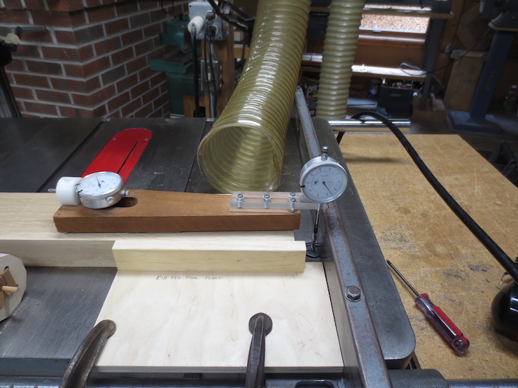
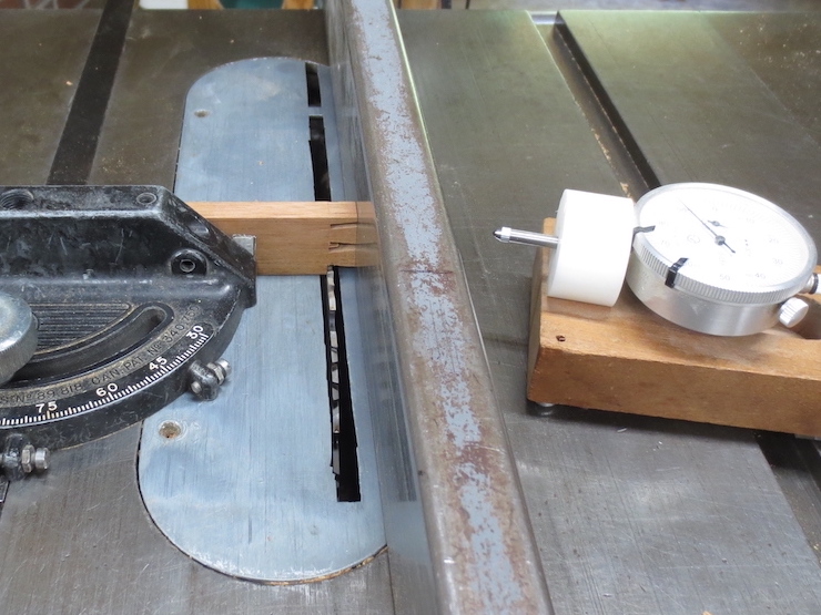
This drill press has a table that can be tilted and is prone to getting out of alignment. A dial indicator mounted in the chuck can be rotated by hand to check this. Small taps from a dead blow hammer are usually enough to correct misalignment. If the spindle is not true to the table (90 degrees in all directions) the holes drilled for rib pegs will tend to push the ribs out at odd angles. This introduces tensions into the structure that may throw the mould out-of-flat and/or out-of-square.
Setting the Drill Press Fence
The center of the rib peg hole, having been calculated, is scribed onto a test block, usually an off-cut or extra piece from the batch of moulds being made.
The hole to be drilled here (in this test piece) has been calculated to make the narrow top edge of the rib end up high by about .010″. This bit of extra wood will allow the ribs to be leveled after the mould has been assembled. Different types of mould will require the ribs to be set at different levels. This is to account for the differing arrangements of laid, bridge and chain wires that will rest on and be sewn down to the ribs. Drawings at the bottom of this post may make this more clear.
A fence is adjusted by eye to drill to the center of the mark. It is clamped to the table with two C-clamps and a test hole is drilled with a brad point drill.
A rib is inserted…
…and the depth of the recess is checked. The drill press fence is then re-adjusted as required before drilling the holes in the actual frame pieces.
Drill the Rib Holes
Try to put the point of the drill exactly in the middle of each mark. I sit on a chair so my eyes are nearly at the level of the table and use magnification to see better.
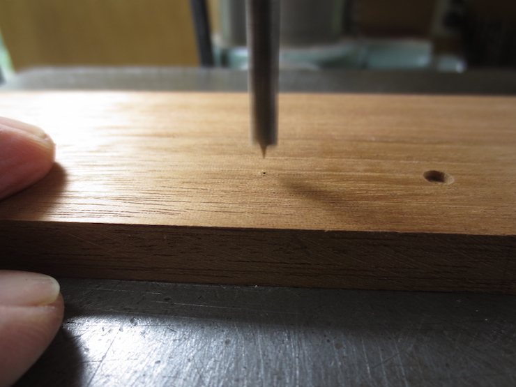
The top edge of the mould frame piece rests against the fence. The hole is drilled from the inside of the mould where the marks have been made. The depth stop of the drill press is set so that only the sharp point of the drill pokes through the other side.
The frame piece has been flipped over to show the tiny hole created by the point of the drill. Using the fence, the piece can be positioned so that the drill point will seek the hole to finish drilling from the other side. This way the hole can be finished neatly without tear out.
As mentioned in a previous post some moulds have blind holes that don’t pass completely through the frame. In my way of thinking a through hole is better. I have repaired old moulds where the shorter blind rib ends weren’t adequately pinned to the frame, allowing the frame sides to spread apart. I also think that a mould with full length rib pegs might dry out a little more quickly after use, possibly helping to prevent decay. There are no concealed pockets to trap moisture (after any amount of use all parts of a mould will be thoroughly soaked) and the exposed end grain of the ribs may actually help wick away the moisture that has accumulated. Moisture enters and exits wood more readily through end grain than it does across the grain.
The sides of the frame are lightly sanded to catch and remove any ragged fibers around the edges of the holes.
Finished rib holes.
A rib seated in its hole in the frame.
The same rib from the other side.
When inserted the ribs should be held square to the frame. Individual ribs will usually curve slightly one way or the other. Turning a rib 180 degrees and checking it twice from the same side will reveal this. If the variation from square is the same both ways the hole is drilled perpendicular to the frame. If not the hole may be slanted.
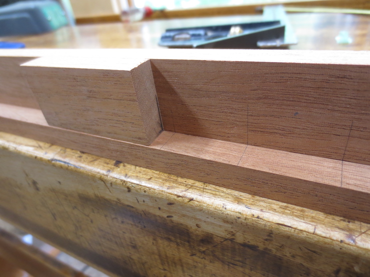
Waterbar notches
A waterbar is a small extra rib that lies closely along the short ends of a mould. The wires of the mould aren’t sewn to it, it just touches the bottoms of the wires that cross it. Notches are routed into the frame to hold the ends of a waterbar. In Britain what I call “ribs” are called “bars”. So “waterbar” might translate to “water rib”. This could be a shortening of the awkward-to-say “de-watering bar”. These little ribs are intended to improve drainage along the short ends of a mould just under the edge of the deckle. Ribs provide pathways for water to flow down and away from the paper being formed on top of the porous wire facing. Including theses small de-watering ribs makes sense for single-faced moulds. These moulds suffer from poor drainage in the areas between ribs so the fibers are deposited on the wires there in a thinner layer. Thicker areas, known as ‘shadow zones’ form along the ribs where drainage is improved by the presence of those ribs. It follows that an extra rib positioned right under the edge of the deckle might improve drainage and help to form a substantial deckle edge there, too. But I’m inclined to think that waterbars are not needed for double-faced laid or wove moulds. In these moulds a layer of backing wires provides more pathways for water to flow along. This more complicated wire structure improves drainage and makes formation very even over the entire top layer of wires and eliminates the shadow zones. I would argue that no extra help from waterbars is needed for these moulds that include an extra layer of wires. Many people make their own wove moulds which must have backing wire of some sort to function well. Most, if not all of these moulds do not have waterbars and don’t seem to need them.
(Though I have long suspected that most waterbars are ‘vestigial’ and unnecessary I do not follow my own advice. Waterbars are still found on all of my moulds.)
This drawing shows the waterbar and how it relates to the inner margin of the deckle.
Mould sides drilled and ready for assembly.
Drilling Sequence
Because the drill leaves a little bump where its point exits the other side of the mould frame I drill only every 5th hole in a pass. This way the bump will hang over the edge of my drill press table and can’t affect the alignment of the next hole as it is drilled. Here I’m on the third round having just drilled the 3rd and 8th holes. (The gap visible between the work and the fence is not normal. My hands are holding the camera and the piece has shifted on the table.)
I don’t like the idea of the bump preventing the frame piece from resting completely flat on the drill press table (having already gone to the trouble of aligning it with the dial indicator). When a side is 1/5 finished I pare off the bumps on the back. Then the piece is returned to the drill press to repeat the process with the next several holes, again every fifth hole (depending on the size of the drill press table). This process isn’t difficult and doesn’t take significantly longer. This is just one more detail that’s intended to improve the outcome.
Making Fine Adjustments
When setting up the drill press the first hole drilled into a test block inevitably needs to be moved a little closer or farther from the top edge of the frame. Here is a simple way to accurately re-position the fence. In the photo I’ve clamped a scrap block of wood with a true flat end tight against the fence. After loosening the two clamps that secure the fence an appropriate shim can be inserted. Then the fence is pushed up tight against the shimmed block and the C-clamps re-tightened, re-positioning the fence BACK by exactly the thickness of the shim. Block and shim are then removed. If the shim is placed FIRST (before clamping the block in place) the fence can be moved FORWARD after the shim is removed.
Waterbar Notches
After waterbar notches have been made in one end of all of the mould frame pieces the stop (shown here clamped to the tablesaw fence) has to be moved to the other side of the router bit.
This is because the notches must be cut from the opposite direction on the other end(s).
Placement of Ribs for Three Types of Mould
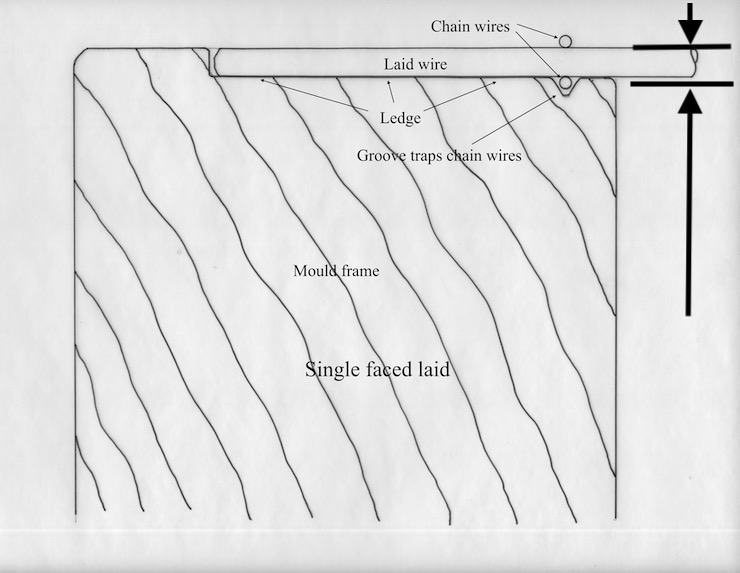
A single faced laid mould will have the ribs set very close to the top of the mould frame. After the tops of the ribs are leveled they should be lower by a little more than the diameter of the laid wires. The level described by the top edges of the ribs is indicated here and in the two drawings below by the lower line and arrow. The upper line shows the top edge of the frame.
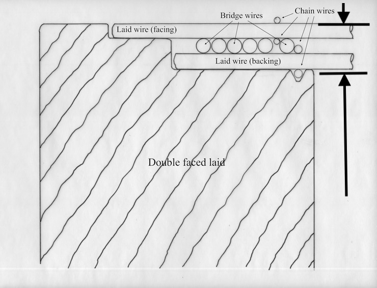
For a double faced laid mould the tops of the ribs should be set considerably lower as shown above.
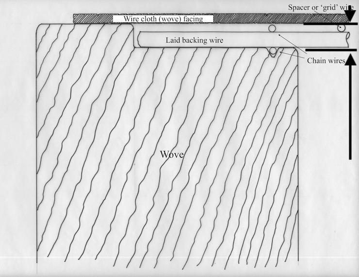
The edges of the wire cloth wove surface generally rest on top of the mould frame. The ribs of a wove mould need to be set at a level to accommodate the diameters of the backing and bridge wires that support the wove facing.
Paper Mould ribs connect with the outer frame by means of small pegs formed on their ends. These rest in holes bored into the frame at regular intervals. The ribs on the left have finished pegs; on the right they are only partly completed. The tool in the middle is used to machine the twelve sided pegs.
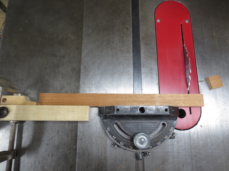
The end of a mould frame is used as a gauge to set the saw fence so the ribs are cut to the exact same length. I drill the rib holes completely through the sides of the mould so the ribs are the same length as the width of the mould. Many moulds are made with ‘blind holes’ drilled only part way into the frame.
A rib is cut to final length. The other end has already been trimmed so both ends are left smooth and square.
1/8″ diameter holes are drilled where the rib peg will meet the shoulder of the rib. This is a stress point and the hole, at least in theory, spreads the stress over a wider area to help avoid splits here.
A cut is made to establish the shoulder of the rib where the peg starts. This is a finish cut and will not be altered when the peg is shaped.
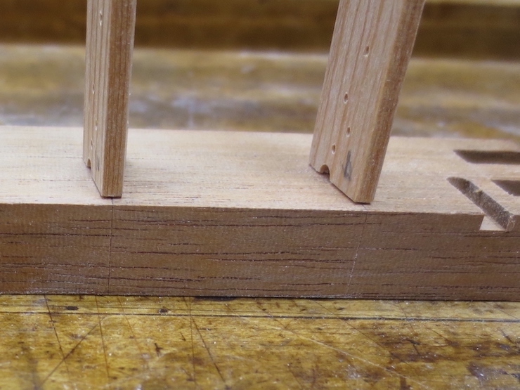
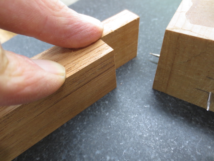
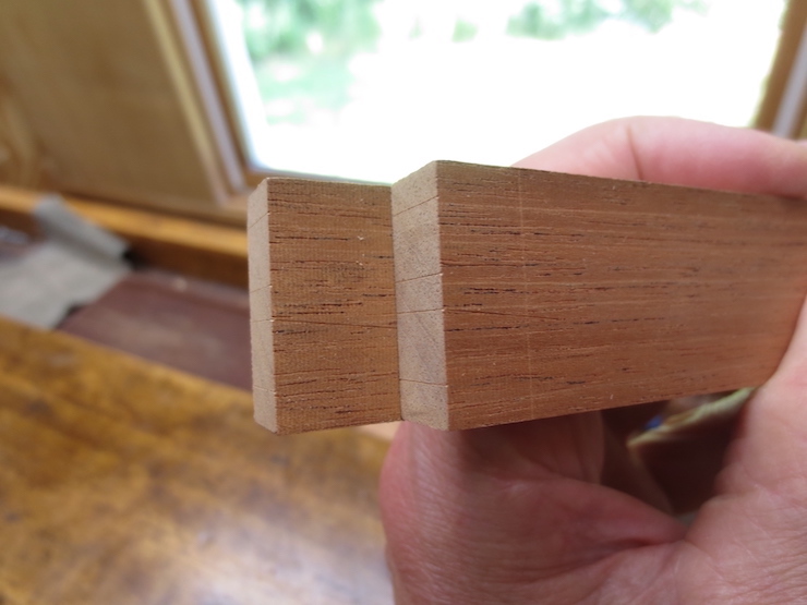
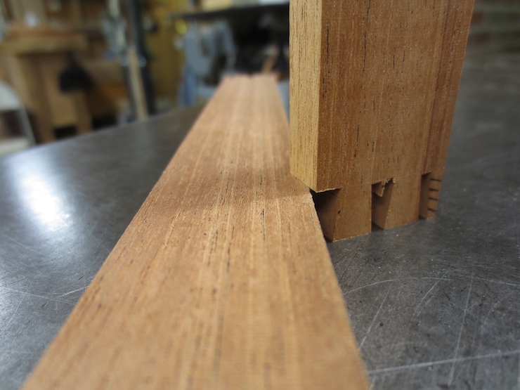
The shoulder is cut back a little so it won’t quite touch the inner side of the frame. You can see that there will be a small space between the body of the rib and the inside of the mould frame. The end of the peg will be exactly flush with the outside.
This is a rough cut made to remove most of the waste before the peg is shaped.
The stub will be shaped into a peg like the finished one on the right.
Ribs for three identical 12″ x 18″ moulds, ready for final shaping.
Shaping the Pegs
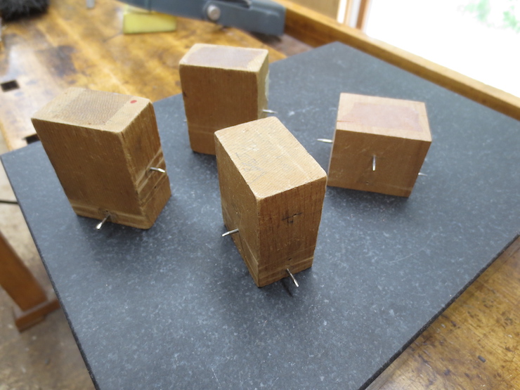
Holes are drilled in a few scrap offcuts. These will be used to test and adjust the fit of the rib pegs. Later the same drill will be used to prepare the mould frame to receive the ribs.
This spiral router bit makes a shearing cut while pushing the fibers upward for a clean cut. The bit is called a down-cut spiral bit but this router is mounted upside-down so in this case a down-cut becomes an up-cut.
The steel table saw fence is adjusted so the peg can be machined for its full length without damaging the previously cut shoulder. The wooden fence guides the rib peg tool while it is slid back and forth and keeps the rib centered over the router bit. The height of the router bit establishes the diameter of the faceted peg.
After making a test cut the dial indicator can be used to make slight adjustments to the height of the router bit to give the peg a good fit with the holes in the test blocks.
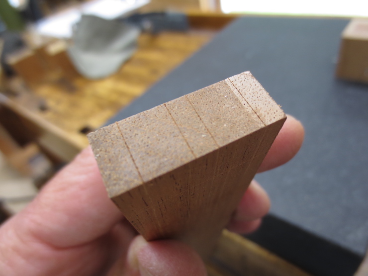
The tool creates a 12 sided rib peg. Later on the facets will be slightly compressed as each peg is twisted into a sized hole in a plastic gauge. This will leave the pegs almost perfectly round and ready to fit into holes in the mould frame.
Details of the Rib Peg Tool
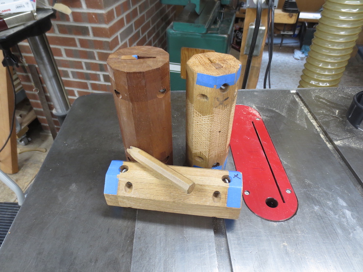
These are peg tools of an older design that I used for many years. Wood shrinks different amounts along and across annual growth rings. For this reason the rib pegs turned out oval instead of round during part of the year. Thus the blue tape added to the two oak tools to correct this problem. The darker tool made of mahogany (which is more stable and shows a smaller difference between radial and tangential shrinkage) was less troublesome. The small wooden ‘scewdriver’ is used to tighten the two recessed thumbscrews which clamp the rib while it is being shaped.
The new tools have ends shaped from plywood which doesn’t change dimension with seasonal humidity.
These are the cores for four different rib peg tools. Each is made for a different size rib. From left to right 15/16″, 3/4″, 5/8″ and 1/2″.
The parts of the tool are held together by the plywood ends.
Another improvement is that the tops of the ribs rest on a ground steel plate.
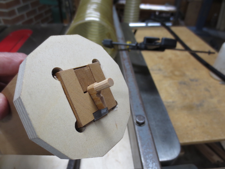
The heads of the hex bolts are tightened with finger and thumb. This works well and no separate tool is needed unlike in the older design. The pressure bar has been slid to the right to show the inserted plastic pad. The bar is correctly aligned in the previous photo.
The two flat head machine screws have smooth rounded ends that can be adjusted to keep the rib centered over the steel plate. You can see the shiny ends in the two photos above.
The grooved pressure bar centers the thick (bottom) side of the rib while the peg is being shaped.
This slide show illustrates the steps of routing a peg on the end of a rib. Notice how the tool makes a complete rotation in 12 steps; each corresponding to one facet of the peg. Keep in mind that for each step the tool is slid back and forth so the router can shape the complete length of the peg (this doesn’t show well here). The router bit only machines the facets of the peg and doesn’t quite touch the shoulder of the rib.
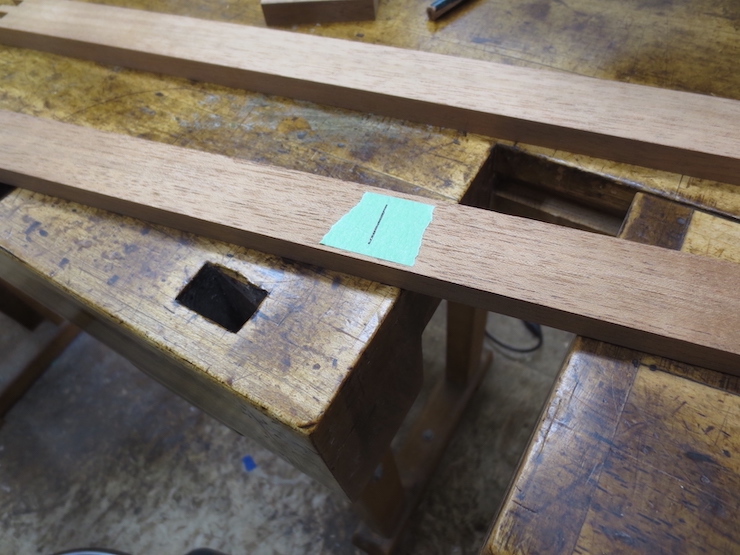
This step is not too exciting but is important. The two long sides of a mould need to be drilled to receive the rib pegs. Marks are made to show the locations of the holes to be drilled. If the hole spacing is erratic or not symmetrical the mould can be thrown out of square. And for a laid mould the notches made in the rim of the deckle should match up with all the chain wires whichever way the deckle is set on the mould. For a pair of moulds sharing one deckle it becomes even more important to lay out the spacing accurately since the deckle should fit either mould equally well, both ways.
First the exact center is found and marked on the inside face of one of the two side pieces.
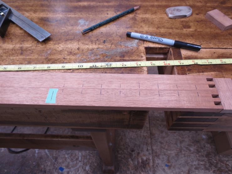
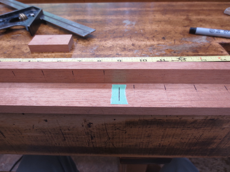
The sides are clamped together so the ends line up exactly and the upper sides touch each other. Then the rib spacing is carefully laid out using a square and a sharp hard pencil. This is done from the middle to one end, marking across both pieces. I am right-handed and tend to hold the square with my left hand and the pencil in my right, working from left to right as shown here. I have accentuated the marks with ink so they’ll show up better in the photos. Notice that the (marked) center of this mould will lie halfway between two ribs. Thus the measurement between the center mark and the first rib line is half of the rib spacing. This mould has 1-1/8″ rib spacing so the first mark is 9/16″ from the center.
One piece is turned end for end and inverted so its top edge rests against the side of the other piece. Once again the ends are clamped between blocks. The blocks are offcuts from the mould frame pieces.
A scrap block with a true 90 degree end is used to carry the pencil marks from the lower piece over to the one that is set on its edge. Using a hard, sharp pencil (I use a 6H) it is possible to locate the point of the pencil partly by feel (where it has indented the wood) so that the square block can be snugged up against it, helping with accuracy.
In this photo I have set one frame piece behind rather than on top of the other. Sorry for any added confusion here; either way works the same. Marks should extend all the way to what will be the inner top edges but need only extend far enough down to cross the place where the rib peg holes will be drilled.
The marks have been transferred and now one piece is fully marked.
Both pieces are turned end for end and laid flat to finish marking the other side piece.
The reason for going through this process is to make the marks along opposite halves of the mould mirror each other (from the center out). This is important because a deckle can be laid on a mould in two possible ways. If the rib spacing is truly symmetrical the little notches under the rim of the deckle will fit neatly over the chain wires either way. If the chain wires are erratic some of the notches will need to be widened or doubled. This might be OK but does not look good!
If a pair of identical moulds are being made for use with one deckle the four sides of both moulds will be exactly the same length. The marks can be carried over to the second pair using the method shown in the photos above.
The last step of the marking process is to carry the marks over and onto the top edges using a marking knife. These marks will be used to help align the ribs and later the chain wires of the laid facing.
To check your work slide one piece over to offset the marks by one space. This will reveal errors in the spacing. I once made the mistake of making a mould with one narrow rib space. This test would have caught the error in time.
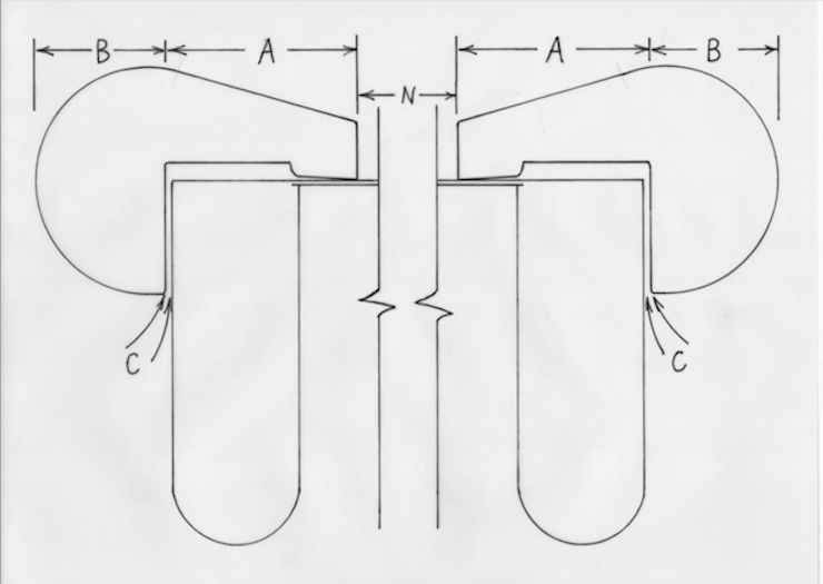
To make the mould and deckle fit together properly you need to know the deckle overlap (A), the width of the deckle (A+B) and the amount of space to leave between mould and deckle (C). More detail on this will follow later in this post.
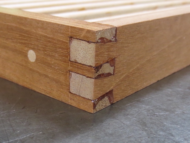
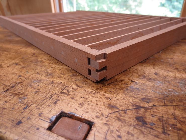
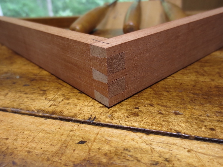
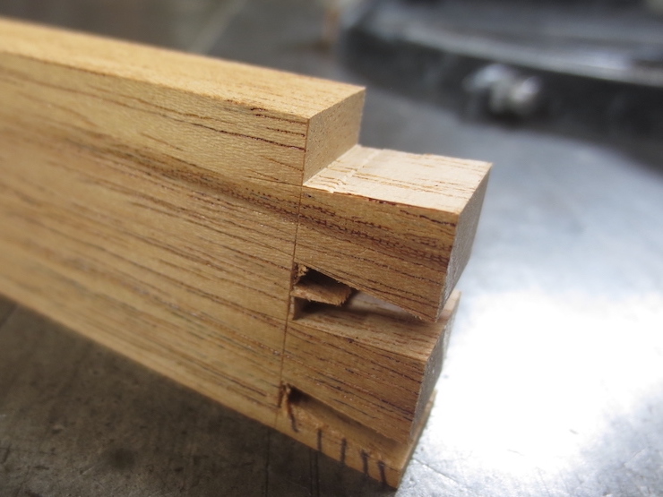
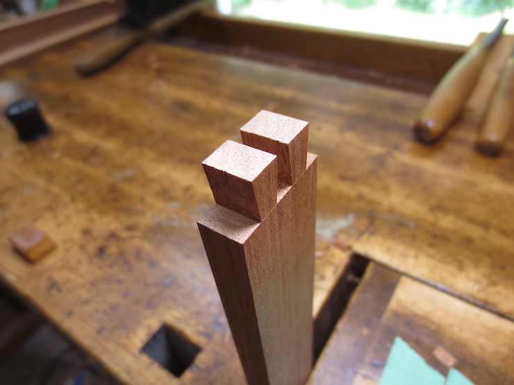
The mould frame is joined at its corners with dovetail joints. The two protruding parts on the left are called ‘tails’ and the three parts on the right are called ‘pins’. Remembering this will make it much easier to understand this post.
Using the hollow ground planer blade the mould frame pieces are cut to exact length with ends that are square.
Using one piece of a mould frame to scribe a line on another. All pieces are scribed this way to begin marking the dovetail joints. Those with tails (the short sides of the mould) are scribed on all four sides and those with pins (the long sides of a mould) are scribed on two sides.
The scribed line defines the bottoms of the joints.
I use a small block of wood with four sharp steel pins to mark the dovetail spacing. The marks are made on the outsides of the long pieces to mark the pins…
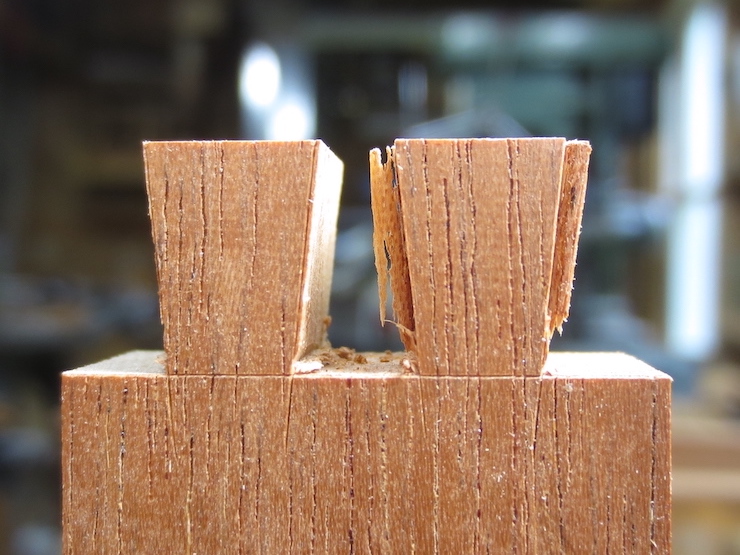
…and on the ends of the short pieces to mark the ends of the tails.
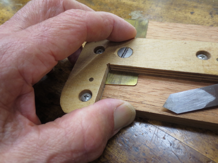
This gauge is used with a marking knife to scribe angled lines for the dovetails. Above, the long side of a mould is being marked on its end for pins; below the short side of a mould is being marked on its side for tails. The longer side of the gauge is always pressed against what will become the top of the mould frame. Since the bottom surface has been left rough, from the saw, it is easy to identify the smooth top reference surface.
The tails are marked the same on both sides; the pins only on the outside. The tool is carefully set to make a slanted mark that matches up exactly with the previously scribed straight mark (where they meet at the corner). After the tool is set it is used to mark all of the joints being made; pins and tails, often for multiple moulds. After all parts are scribed the brass blade is re-adjusted to mark the second dovetail and the process repeated. Then the blade is flipped to reverse the angle and the process is repeated to scribe the other two sides of the dovetails.
The short pieces which will form the ends of the mould showing the tails marked with parallel marks on their ends and angled marks on their sides.
The long pieces which will form the sides of the mould are marked with parallel marks on their sides (difficult to see) and angled marks on their ends.
Rough out waste wood
I usually make a few moulds at a time. If the joints are identical it is easier to do some of the work by machine. When making one mould at a time it might be easier to do more of the work by hand.
This tool is used to hold the parts straight up at 90 degrees to the table so accurate cuts can be made at the ends using the hollow ground blade. Here a block of wood is screwed to the side of the tool to hold the pieces at an angle that matches the dovetails on the pins (6 degrees here).
You have to keep your wits about you to keep from making mistakes. The pieces must all be oriented the same way with the (smooth) tops on the same side and the outsides facing forward. The fence of the tablesaw is re-set for the cut between each pair of pins. The block that establishes the angle is moved to the other end of the tool to reverse the angle for the other sides of the pins.
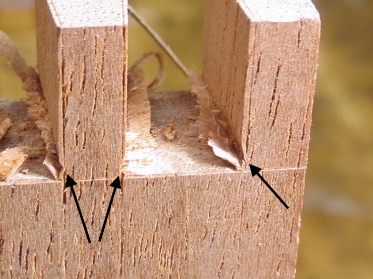
Notice that the scribed lines are still clearly visible. They will be used to guide the chisel when the joints are pared by hand to their final fit.
Removing the block holds these pieces at 90 degrees to the fence. Now the saw is tilted to 6 degrees to cut the angled sides of the tails.
The short pieces on the left are extras. I always make a few shorts that are used as test pieces when making adjustments.
Again, the scribed lines are left to guide hand work.
Machine trim tails and pins
Now the shoulders of the tails are trimmed using the hollow ground blade (now set at 90 degrees). This is not a rough cut; it will be the final cut for this part of the joint. The dial indicator makes it possible to make very fine adjustments. Once the fence is set all of the parts are trimmed exactly the same.
The machine work is finished for the tails.
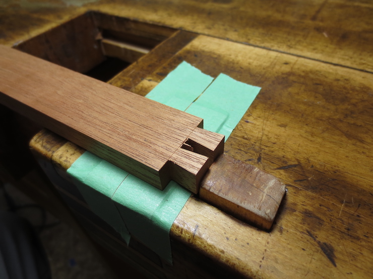
The space between two pins is being routed out to establish surfaces at the bottom of the joint. The router bit is set to exactly match the thickness of the frame parts. The block of wood at the far left is a stop that is clamped to the tablesaw fence to limit the cut.
The pieces are only routed out a little bit…
…from both sides. The little ledges make it easy to position the chisel to trim out the bottoms between the pins.
Final fit by hand
Now the joints will be pared by hand using the scribed marks to guide the chisels.
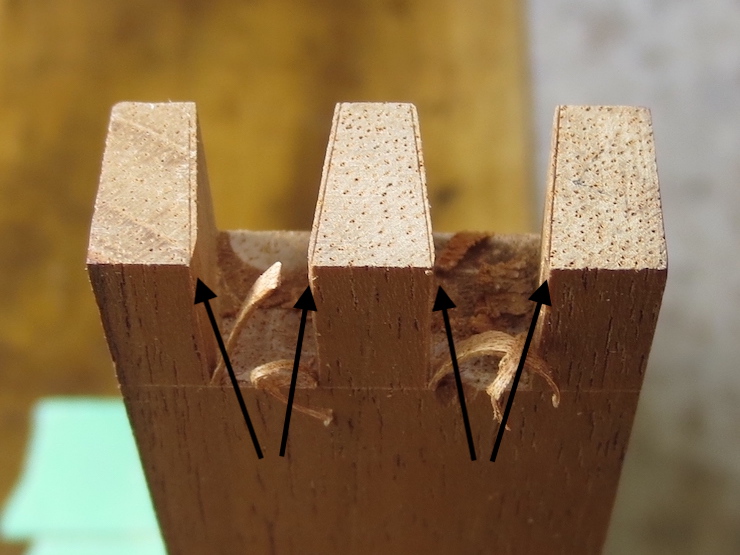
The flats between the pins have been chiseled out using the routed surfaces as guides. These surfaces should ideally be flat but it is more practical to make them ever so slightly hollow. When the back of a chisel is laid flat there it should not rock on any high spots. (Better to have low spots). Using the scribed parallel lines to start the chisel, the sides of the pins are refined, using the slanted lines as guides. The photo above shows two sides just started. The pins are pared from one side only; there are no lines scribed marking the back side of the joint.
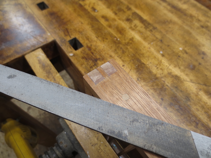
The tails are pared in a similar way after the flat between the tails is chopped out at the scribed line. The chisel is started in the angled marks and the parallel marks are used as visual guides. The chisel can be located in the scribed marks partly by feel, though I have to use my head mounted magnifier for most of this hand work. The tails are pared halfway from each side; the angled marks have been scribed on both sides.
The finished joint. It is usually necessary to pare little bits off here and there to get the joints to fit just right. Some folks would want to cut the joints entirely by machine which is certainly possible. But a slight miscalculation using a machine makes it easy to make a lot of scrap in a hurry. I prefer a safer approach and find it satisfying to do this part by hand.
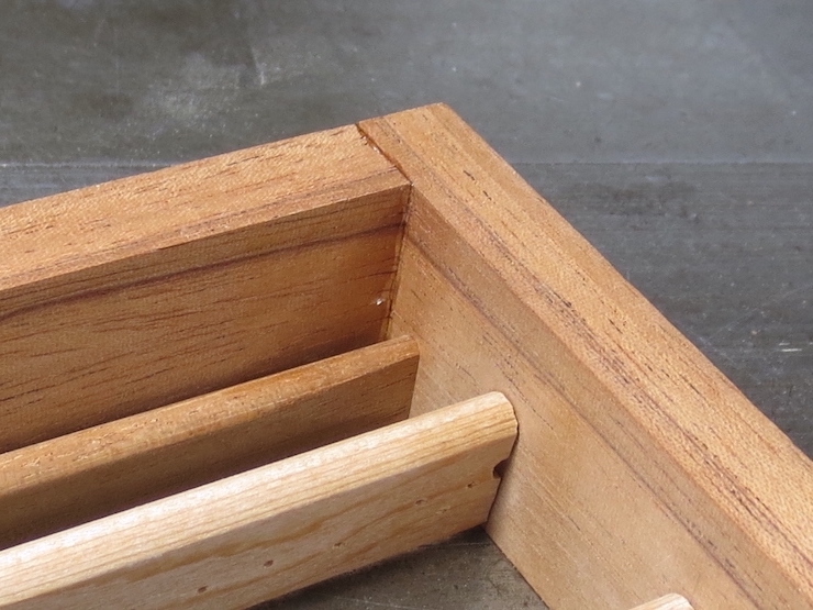
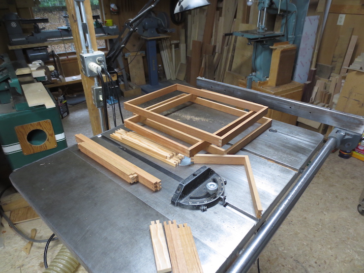
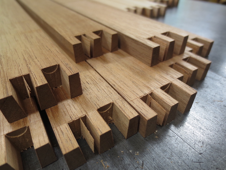
Mould frames after final fitting. There are a few extra pieces here that won’t be used. The four pieces of lighter colored wood are an experiment. They will make an A4 size wove mould made entirely of Larch.
More detail and a few tips.
For most of my career A (the deckle overlap) measured 3/4″ and B measured 1/2″. The total width of the deckle was 1-1/4″. For the space between the mould frame and the inside of the deckle (C) I use .015″. If a mould was to make a sheet 12″ x 18″ the drawing would work like this: For the short side 12″ (N) would be added to twice the deckle overlap (A) to give 13-1/2″. From this twice the desired space (C) is subtracted. The result for the two shorter frame pieces would be 13-1/2″ minus .030″. Calculating the length of the deckle pieces is easier; they would measure 12″ plus twice the deckle width (2-1/2″) or 14-1/2″. The same calculations are made for the longer pieces, substituting 18″ for 12″ at (N).
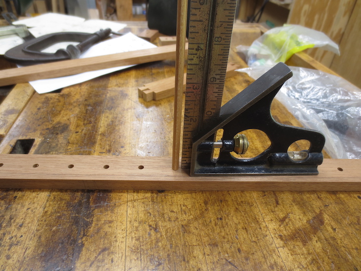
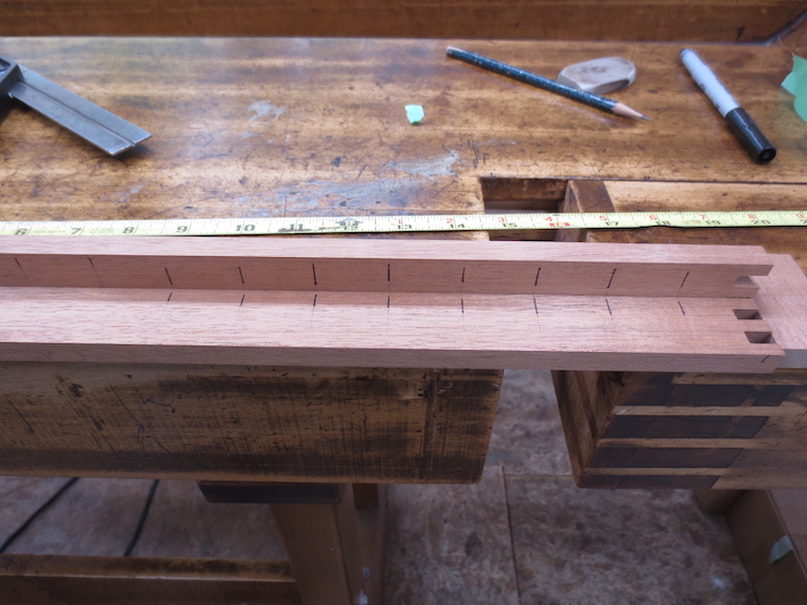
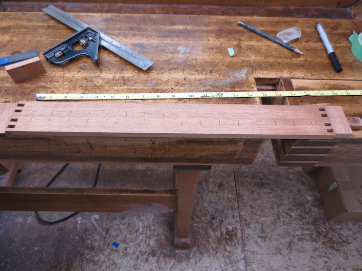
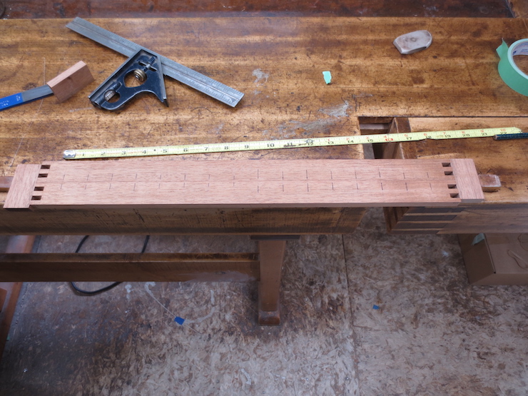
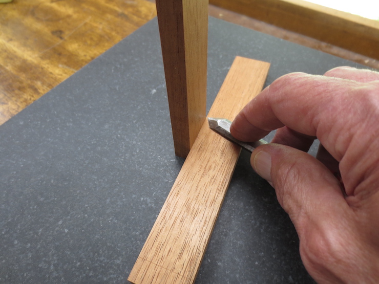
This measuring tool is better than using a tape measure. The beam is scribed in 1/2″ increments and should be long enough for your largest mould. The small block with white plastic guides is clamped so that its near end aligns with the desired mark. The trimmed end of a mould part can be pushed against the block on the left and scribed at its other end for an accurate measurement.
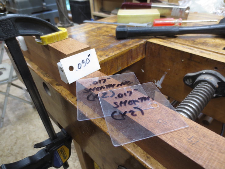
Here the tool is set to mark the long side of a 12″ x 18″ mould so the moveable block has been set for exactly 19-1/2″ (using the above calculations). The .030″ shim reduces the length to create the .015″ space at both ends.
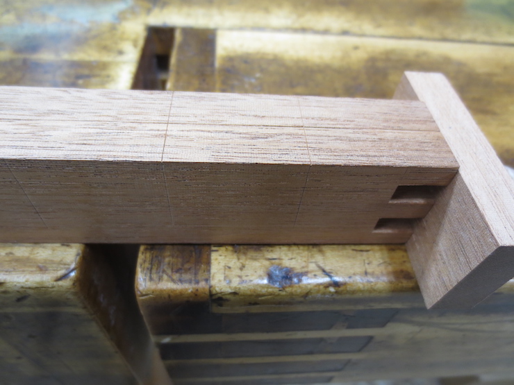
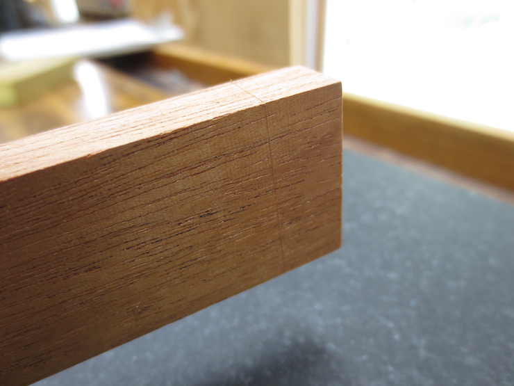
This is a rough piece of wood, used as an example. But if it were an actual frame piece the left end would contact the shim. This would reduce the length by the desired .030″ when the length is scribed as shown here.
If the mould is to be sheathed with brass sheet two additional shims are added. They are the same thickness as the brass that I use (.017″)
The saw is being set to cut at the scribed mark made using the measuring beam. If the deckle pieces and mould frame pieces are all measured with the same device the results are more predictable and the fit is likely to be better.
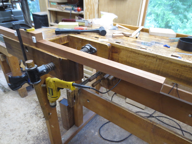
Since I use epoxy to glue the joints they will be rigid. If slightly out of square pieces are clamped and glued they will likely force the frame out of flat. To avoid this problem any out of square pieces can be corrected with couple of swipes using a block plane and the method below.
The blade is very sharp and set for a fine cut. The middle is planed hollow as shown above. Then the bed of the plane behind the cutter is set firmly down on the low side and a fine cut taken off the high side. Check for square and repeat if needed. This adjustment only needs to be made for the longer dimension as shown above. The short dimension isn’t as important.
Different dovetail spacings each need a scribing block.
When trimming the shoulders of the short sides you can check the fit like this.
Raising the saw just enough to score barely across the scribed lines leaves a visible line that helps when paring the sides of the tails.
Before routing between the pins the router bit is set at exactly the thickness of the mould frame pieces using the dial indicator.
Note: (This batch of small moulds is made with different dimensions than my old standard; the frame pieces are 7/16″ thick (.437″ on the dial indicator shown above). For years the small moulds I have made seemed over-built. I now make smaller moulds a little lighter. These moulds have 11/16″ deckle overlap, 1-1/8″ x 3/4″ deckle parts. The frame parts measure 7/16″ x 1-1/8″. The ribs are 5/8″ deep with 3/16″ diameter pegs. The space between mould and deckle stays the same at .015″ all around.)
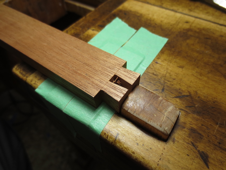
These routed ledges make it easy to trim the bottoms of the joints flat between the pins.
The frame piece dogged flat on the bench for trimming between the pins.
The joints of the pins are not scribed on the inside. Chiseling off these corners keeps the chisel from splitting them off when the joint is pared from the other side.
It helps to cut these grooves (with a small chisel held at an angle) before paring the sides of the pins. Then the chisel is kept just above these grooves so the parings can easily fall away. If the grooves aren’t there the uncut fibers of the wood at the bottom will pinch the chisel there making it harder to control. The corners can be cleaned out after sides are made flat.
A sharp chisel’s edge can be started right in the scribed line…
…and pushed straight down to trim between the tails. The piece is flipped and the process repeated from the other side.
With a little careful guidance (and visual magnification) a sharp chisel will seem to find its own way into the scribed lines to start the paring cuts.
A finished pair of tails.
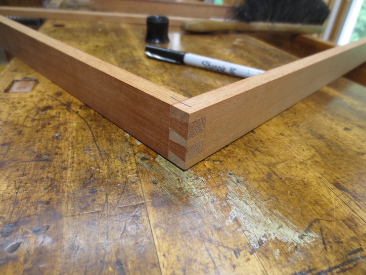
Pins and tails fit together to make a very strong joint.