This is the last of four posts describing this way of shaping a traditional deckle joint.
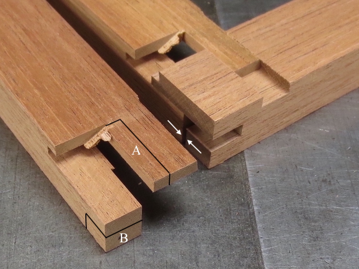
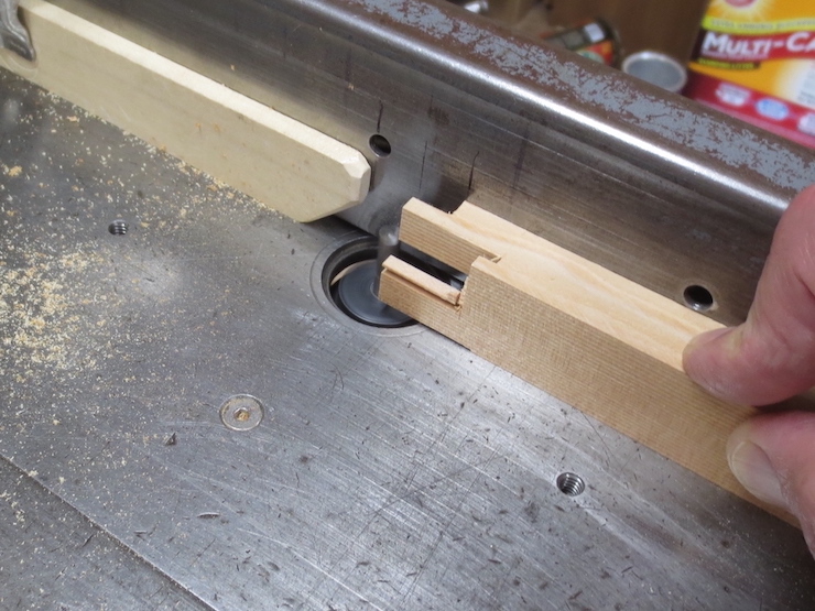
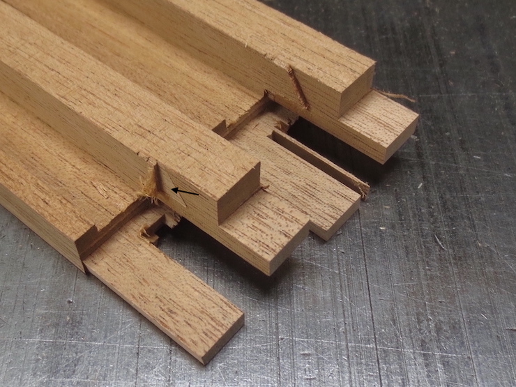
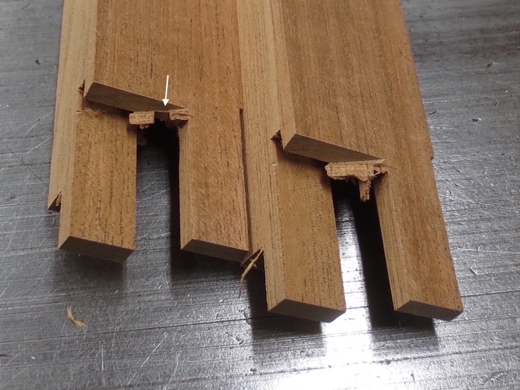
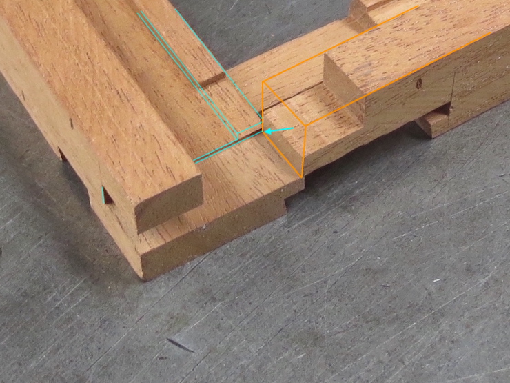
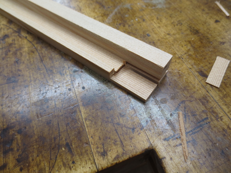
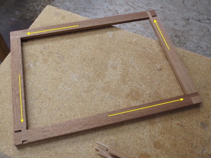
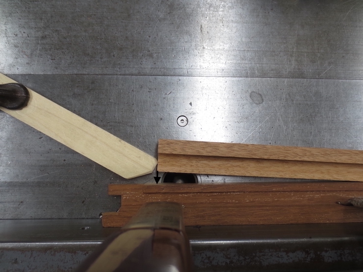
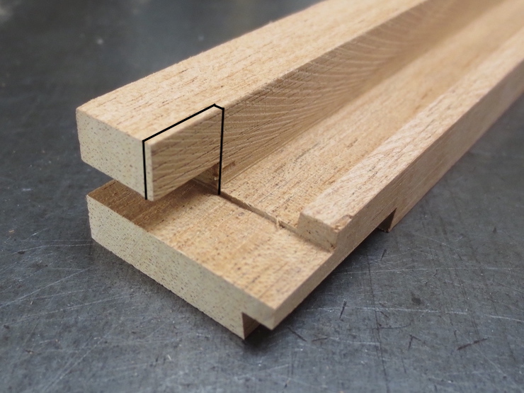
At the end of the previous post we left the joint at the stage shown at the back. Cutting away the part labeled “A” has made it possible for both tenons to slide partway into the joint but the end of the lower tenon (marked “B”) will bump against another part before the joint can close very far. The two white arrows show where this will happen. Cutting away the area marked “B” will let these parts lap over each other to enable the joint to close farther.
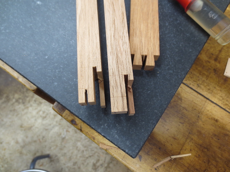
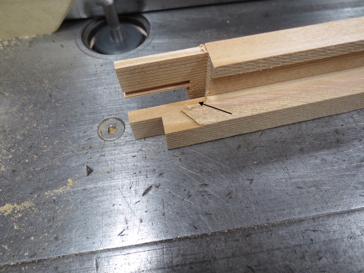
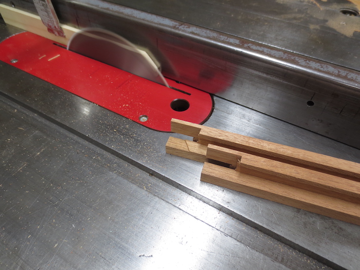
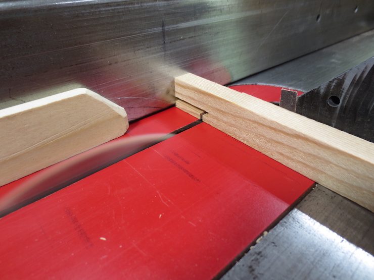
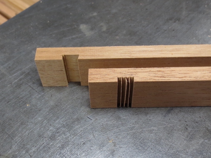
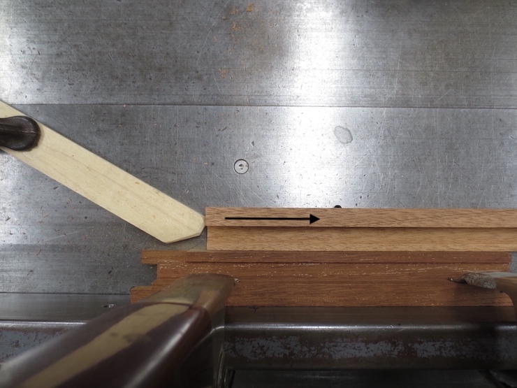
The piece at the left has received a saw cut, the first step in removing ‘area B’ (above). A line has been scribed with a marking knife to reduce chip out.
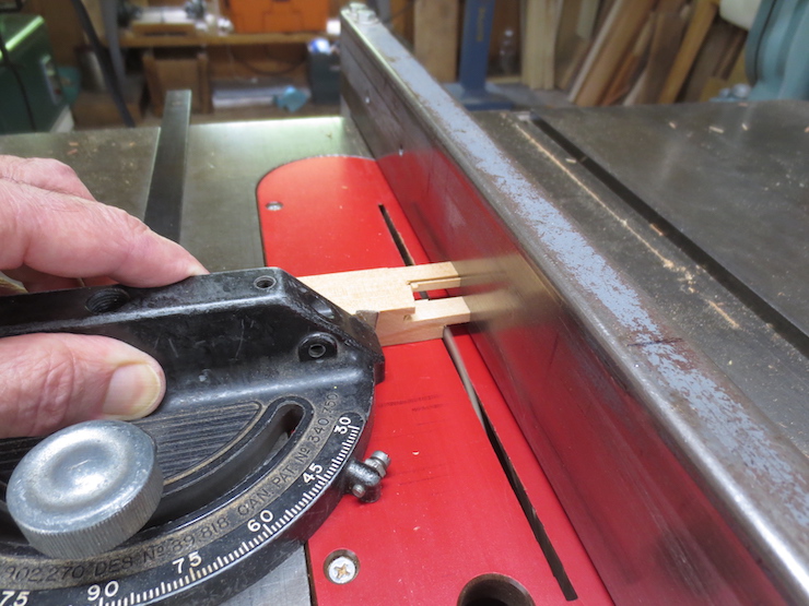
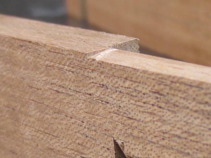
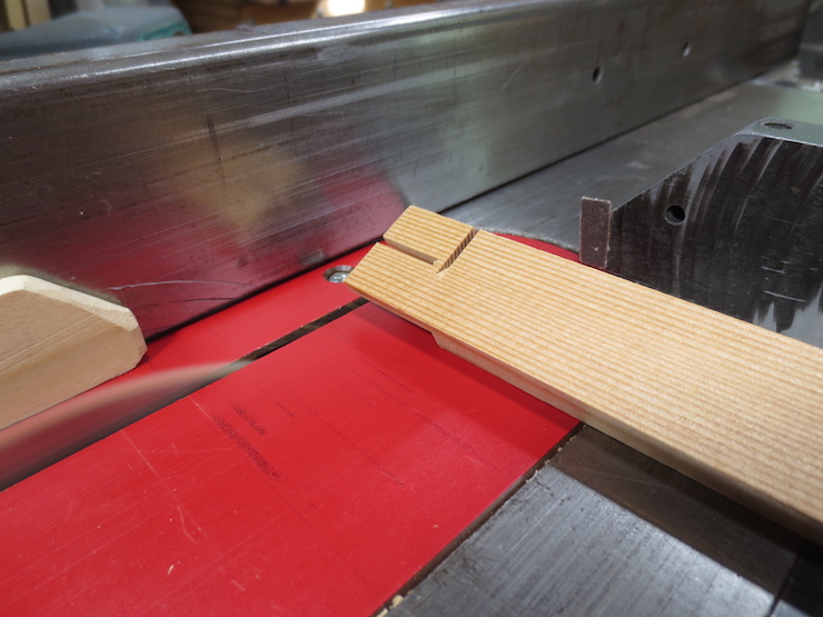
A cross cut finishes this part of the joint so it can lap over the other half.
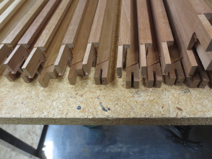
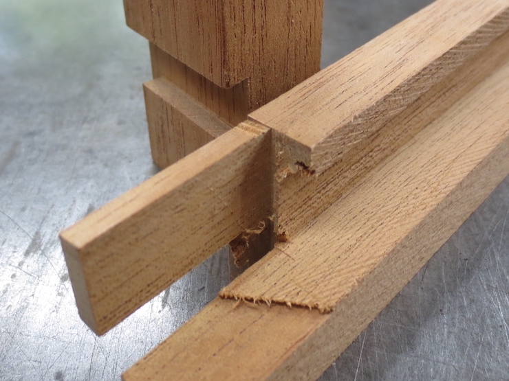
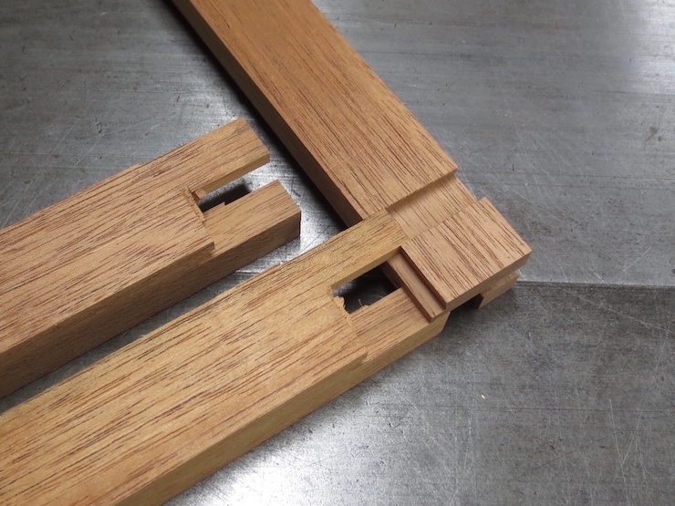
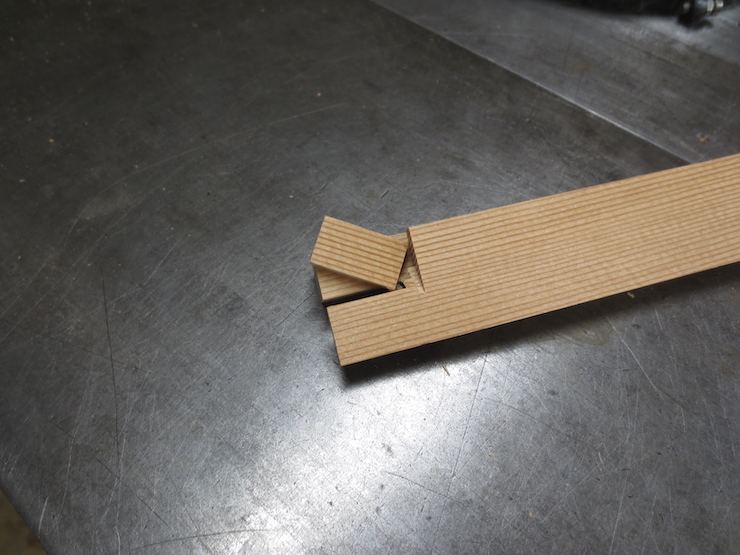
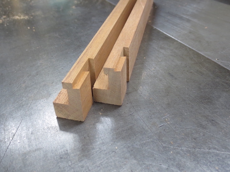
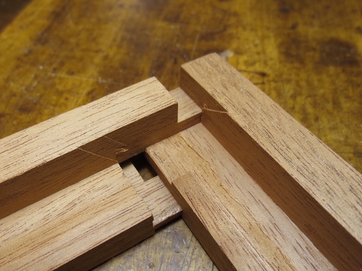
The parts on the left have completed lap joints; at the right the cross cuts haven’t been made.
The following five illustrations show unnecessary steps. The updates are indicated below in boldface along with three more illustrations of a better method.
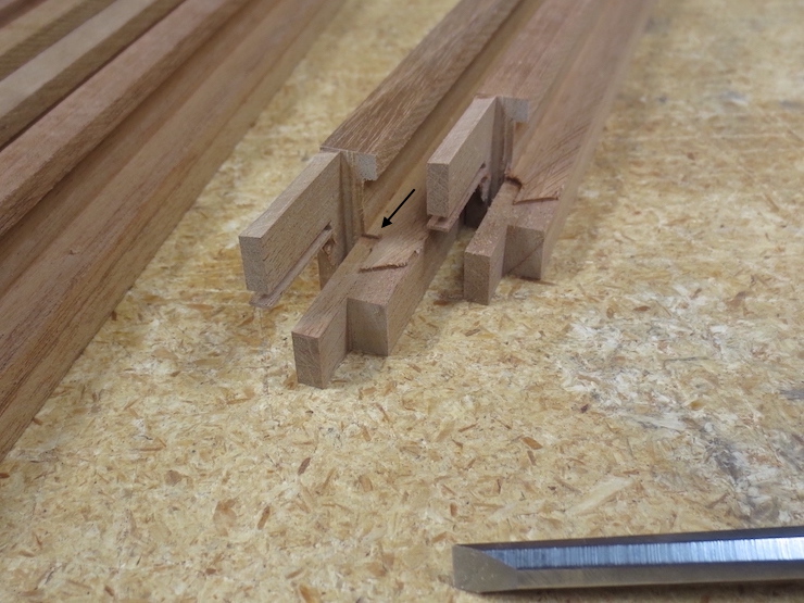
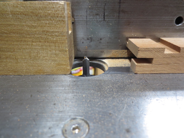
This step routes away the next area that needs to be removed.
After the cut it looks like this. If not removed, this area would be the next hindrance to closing the joint; the next place the parts would ‘bump’. Note: routing away the deckle rim ahead of time or merely chiseling away one corner makes the cut shown by the arrow unnecessary. (See photos at end of post)
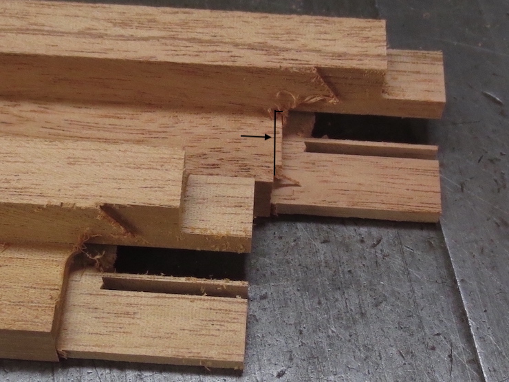
The radius left by the router is chiseled square (at the arrow).
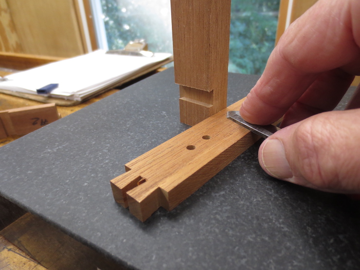
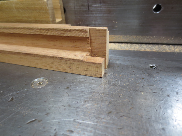
Next the shoulder is widened on the underside of the dovetail tenon. When finished (as shown in front) it lines up with previous cuts made across the deckle rim and at the slanted side of the tenon. You may recall that these were both cut to the exact width of the deckle pieces. The line and arrow show where the part in the back still needs to be trimmed. Note: Altering the joint a bit to put the bottom of the deckle groove in the same plane as the slot eliminates the need to trim this waste.
This is how this cut is made.
Photo updates: (There is always more to learn).
For this batch of deckles the joint has been altered to put the top of the slot at the same plane as the bottom of the groove that runs around the inside of the finished deckle. In the photo above the deckle rim on the left has been cut back to its final shape. Doing this step now rather than latermakes the previous steps unnecessary.
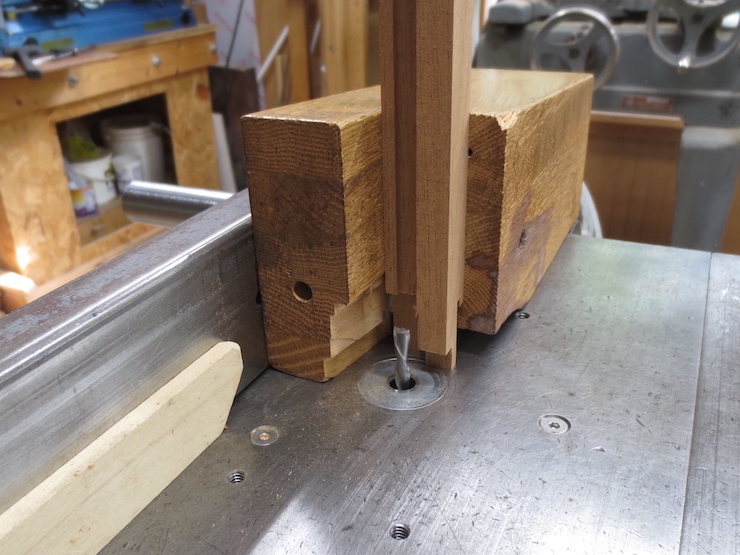
The set-up for routing away the waste part of the deckle rim.
The saw blade is tilted 9 degrees for the next cut.
This allows the part to be cross cut at a 9 degree slant. The black arrow indicates the finished cut.
This shows how this slanted ‘dovetail’ face fits with the other side.
For this batch I made one more small cut from the bottom. This was not truly necessary but made it easier to chisel away the waste. Below the arrow you can see the routed area extending down into the waste.
This is the set up used to route away the area shown below by the arrow.
The same cut seen from the other side.
The uncut portion in the corner is pared away from both directions until the cuts meet and the waste falls away.
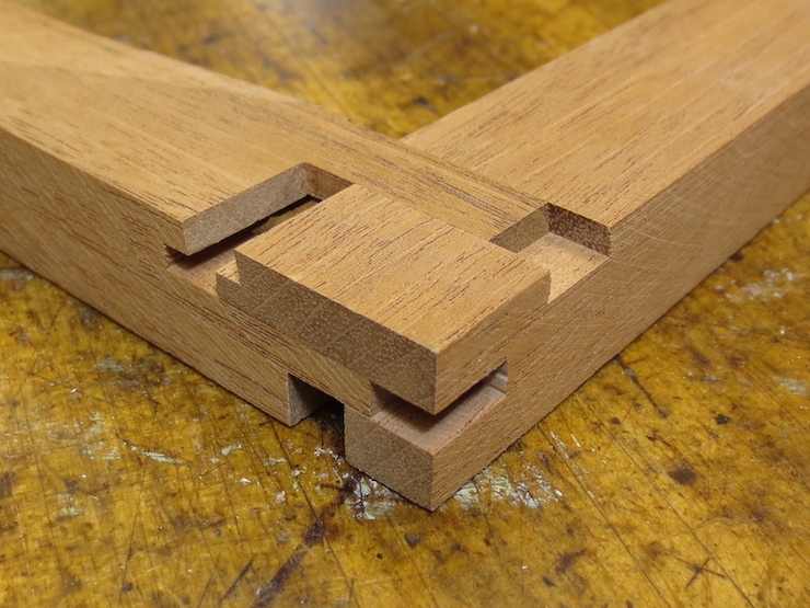
The joint is finished!
The parts of the joint now fit nicely together but several more steps remain to complete the deckle.
Edits to this post:
Chiseling away the corner makes routing a groove unnecessary.
After final trim the bottom of the deckle groove will be an extension of this surface of the joint.
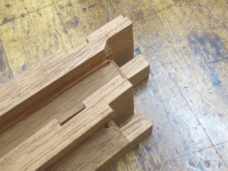
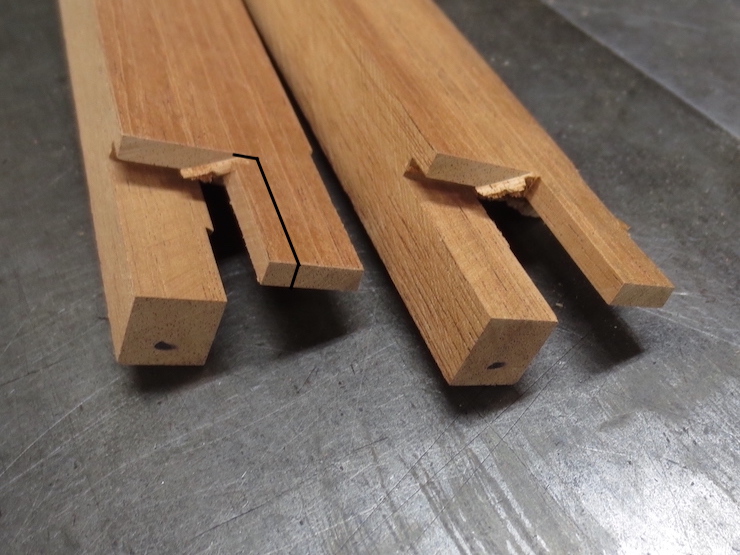
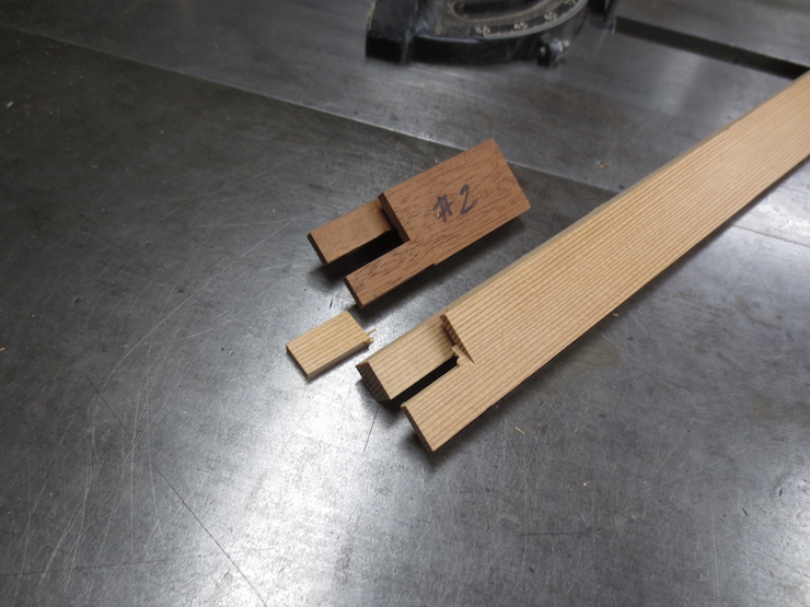
The end of the last post left us with two tenons ready to be fitted into spaces left in the other half of the deckle joint. Both tenons were cut to the correct thickness and now both need to be trimmed to width.
The simpler lower tenon is the first to be fitted. It only needs trimming on one side. The finished width is indicated by the black arrow.
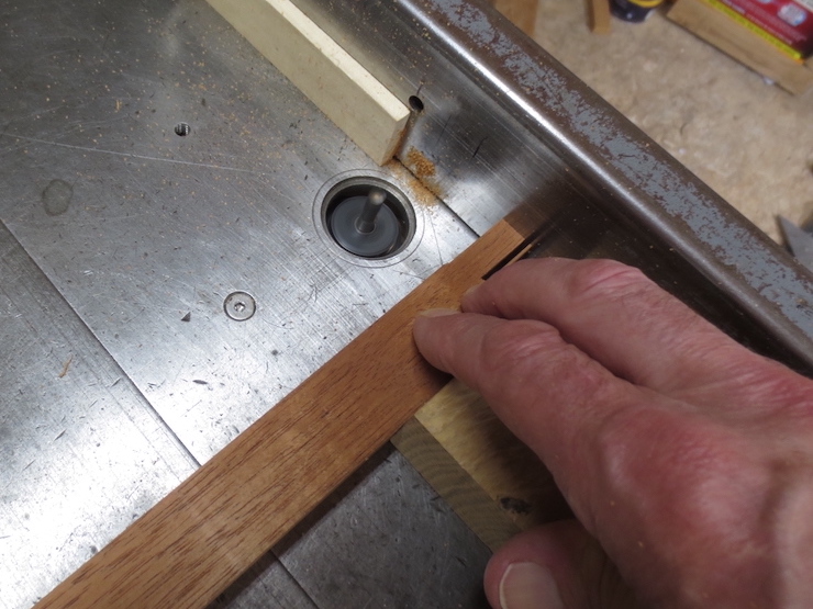
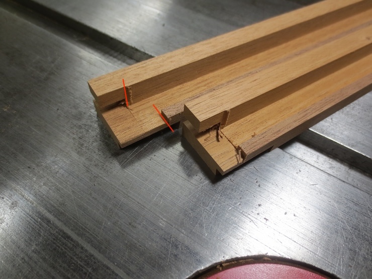
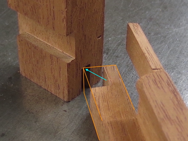
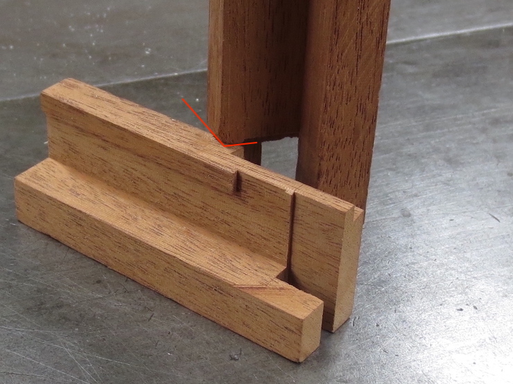
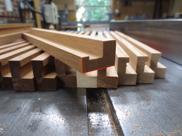
This is a view of how the width is tested. The corner indicated by the arrow should slide into the opening in the other piece. Since I neglected to photograph this step the orange lines have been added to show what the part would have looked like.
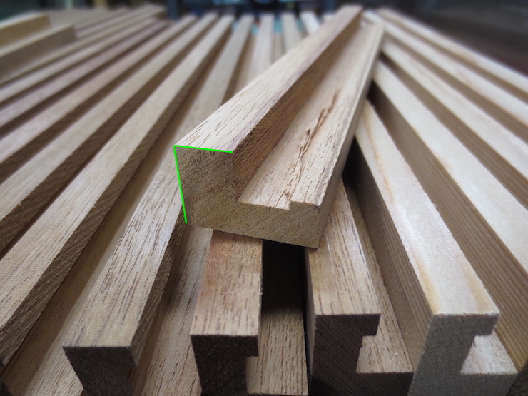
This photo shows how the width of the tenon must be sized to fit alongside a narrow edge in the other part of the joint. Again, the orange lines show how the part would have looked. The arrow points to the bottom corner of the inner vertical surface being fitted (hidden in the photo). The blue lines show how the other part would have looked at this stage. In practice the fit would be tested with the part on the left standing on end and both pieces resting on the flat surface. (This was difficult to photograph).
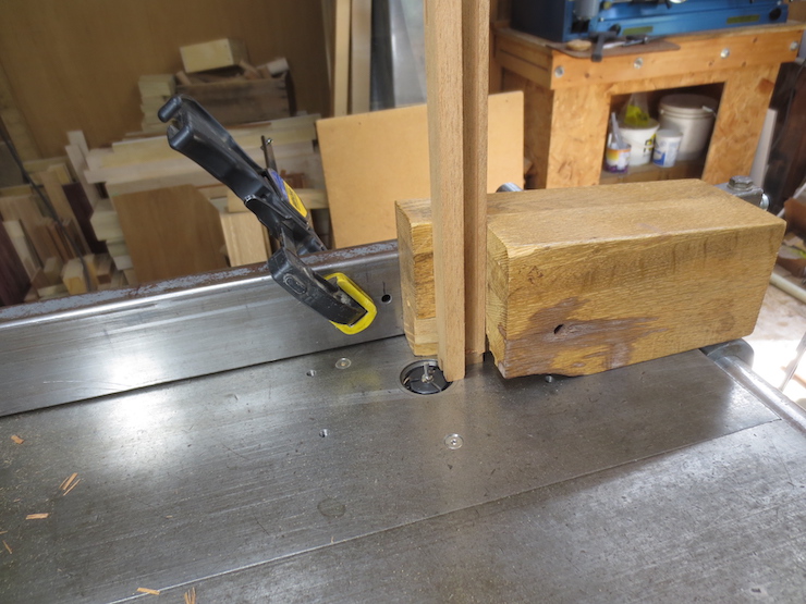
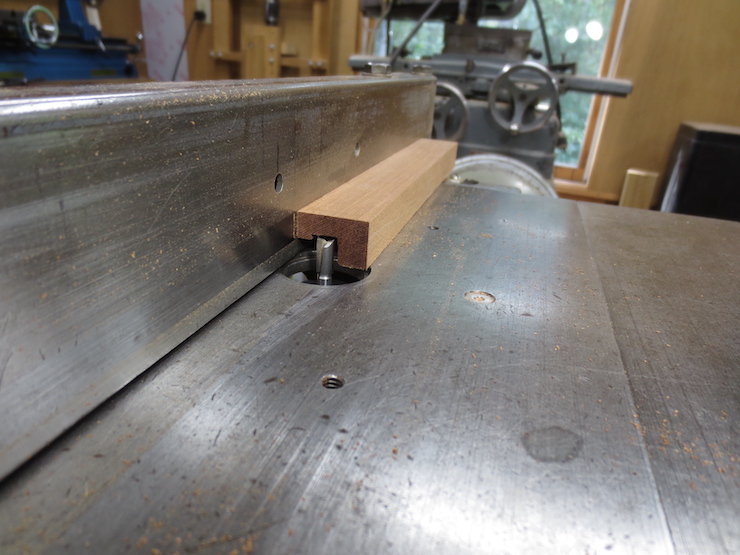
Here the fence of the table saw is set to trim the proper width and a stop keeps the cut from going too far. One part has been left un-sawn to show what the cut looks like. Fitting this tenon first allows the lap joint parts to slide past each other so the more complicated sliding dovetail part can also be tested, trimmed and fitted. If left untrimmed the lap joint would block the sliding dovetail from ‘starting’ in its groove (which is essential for testing its fit).
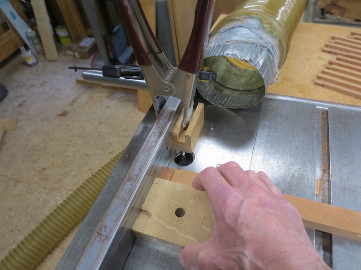
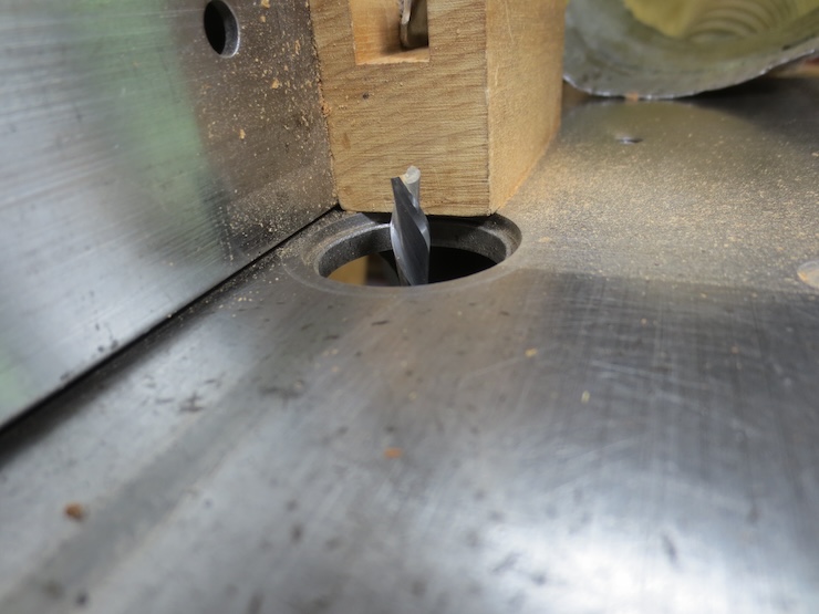
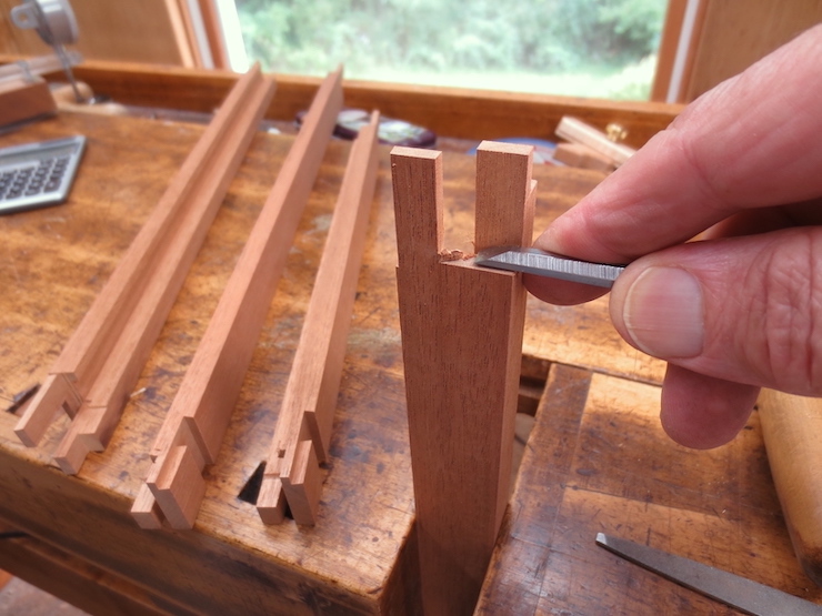
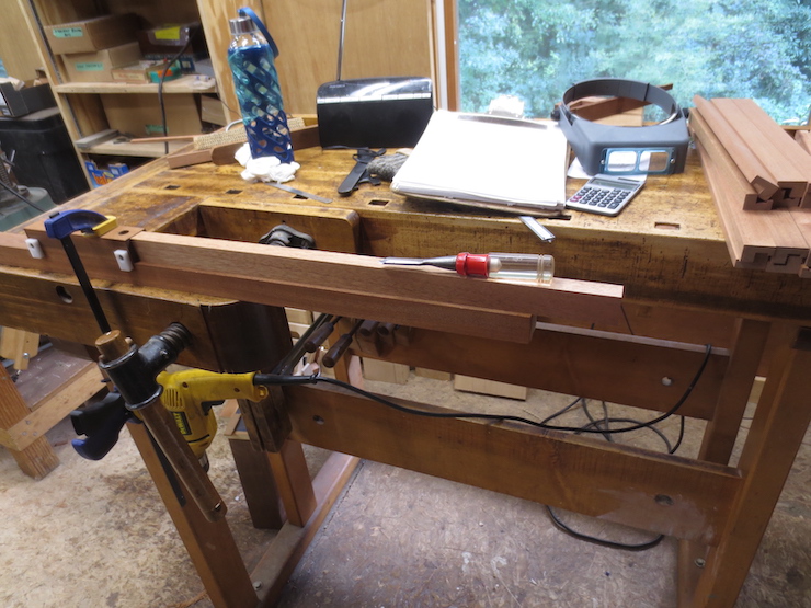
A very small cross cut is now made to establish the shoulder of the sliding dovetail tenon. It should line up perfectly with the previous finish cut across the deckle rim. (In the photo the fence still needs to be adjusted to make the cut a little further to the left). The saw blade is set to barely protrude from the top of the table saw and a ‘stop’ is used. The blade setting and the position of the stop must be ‘fiddled with’ more than usual to get the adjustments right before giving all of the deckle parts these tiny cuts.
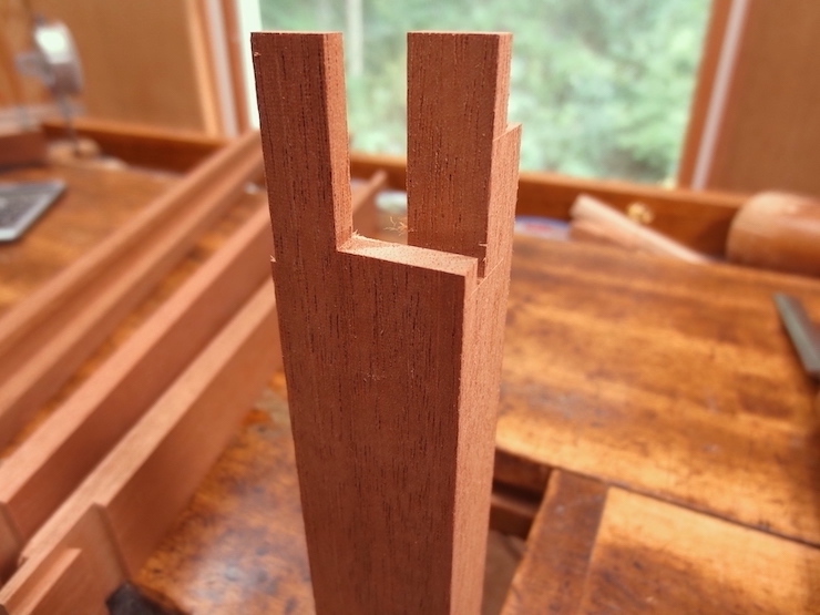
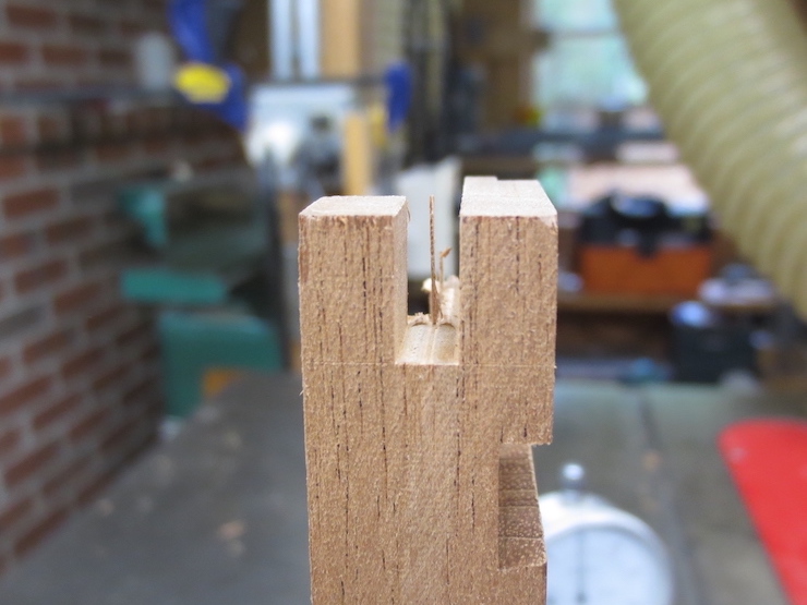
The shoulder now lines up perfectly so the sliding dovetail will be able to reach full depth in the groove after its sides have been trimmed.
The right angle block is canted 9 degrees by a special block screwed to one end. This enables the side of the tenon to be sawed to match the angled face of the dovetail groove.
The part on the left has had its 9 degree angled face sawn; the part on the right has not yet been trimmed.
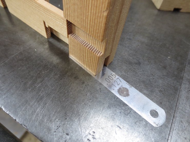
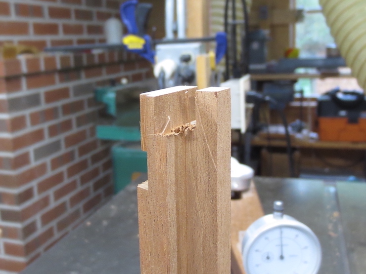
As a first step the slanted edge of the dovetail tenon has been left a little ‘fat’. This photo shows a way to determine how much more needs to be cut away. The fit turns out to be good when the previously cut half of the joint is elevated on a .005″ shim (this has been determined by trial and error, the shims being in .001″ increments). This means that .005″ more needs to be trimmed off of the slanted side of the tenon. With the help of the dial indicator fixture the table saw fence can be moved precisely this amount to re-saw the part and correct the cut.
When all parts are trimmed a chisel easily removes the little bits that are left at the shoulders.
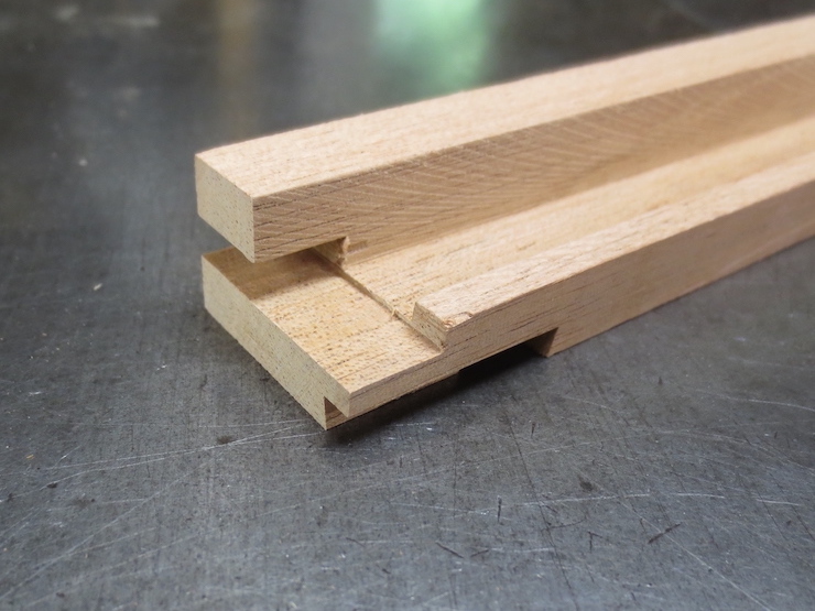
The slanted face has been correctly fitted and now the tenon needs to be cut to width so it can slide into the groove. The black lines show the part that needs to be cut away. The piece on the right has already been trimmed.
Using the dial indicator to adjust the table saw fence, the width of the tenon is reduced in small increments until the test part slides nicely into the half dovetail groove. Then all of the parts are trimmed the same. Before the joint can close completely a few other areas must be trimmed away. This will be described in the next post.
The next three posts will show how the other half of the deckle joint is made. This half of the joint takes longer so the process is broken into segments.
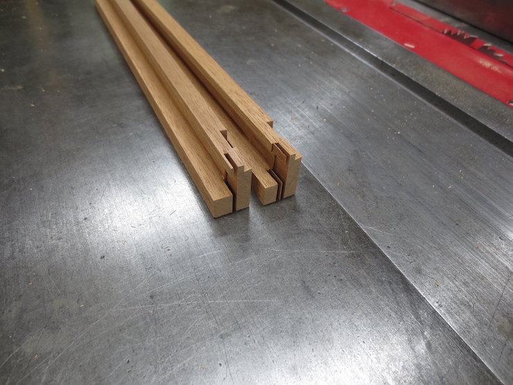
One side of a saw cut establishes the bottom surface of the sliding dovetail; making it the right thickness to slide into the dovetail groove. The same saw cut starts a slot to fit a tongue that has already been made. Since both tongue and slot are the full width of the deckle, a deckle part can be used as a gauge when scribing the part (above) to prevent ‘chip out’ when the saw exits the cut.
Here is how this slot is cut using the right angle block.
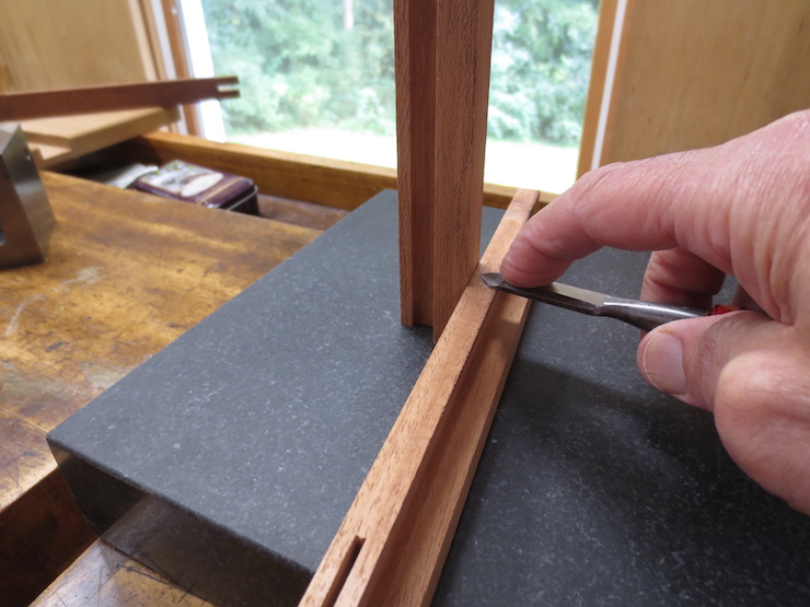
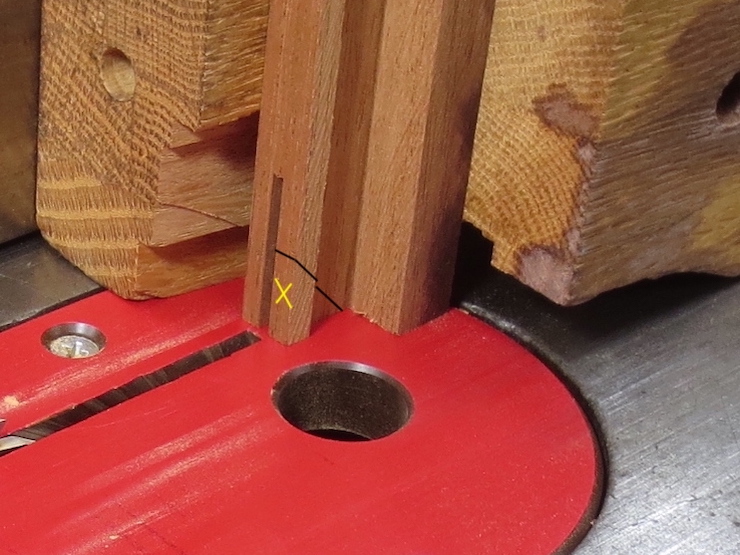
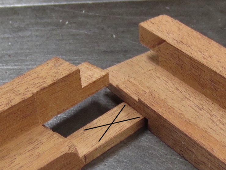
Some waste can be sawn or chiseled away after removing the test part from the saw. The black line shows the imaginary saw cut and the waste is marked by the yellow “X”. Removing this bit of waste (only on the test piece) makes it possible to test the end of the dovetail tenon against the slot it must fit into. (See photos at bottom of post).
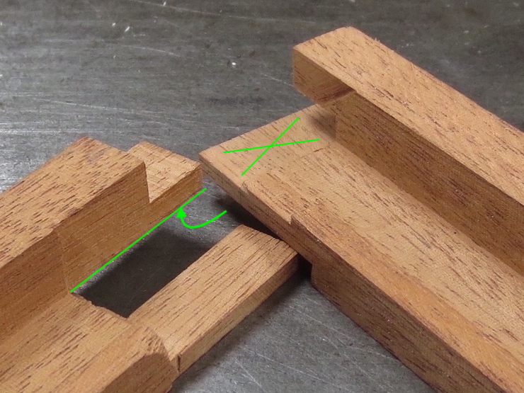
The thickness of the sliding dovetail (indicated by the black arrow) can now be tested and trimmed to fit the groove. The first cut leaves it slightly thick on purpose. In one or more tries, the table saw fence is reset (with the help of the dial indicator fixture) to improve the fit of the scrap test part. When the fit is good all of the deckle parts are cut the same, finishing this step. Next the slot must be widened (by moving the fence and making another saw cut or two) to fit the ‘tongue’ that was previously shaped on the other end of all the deckle pieces. The green line shows how the slot will be widened.
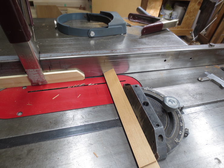
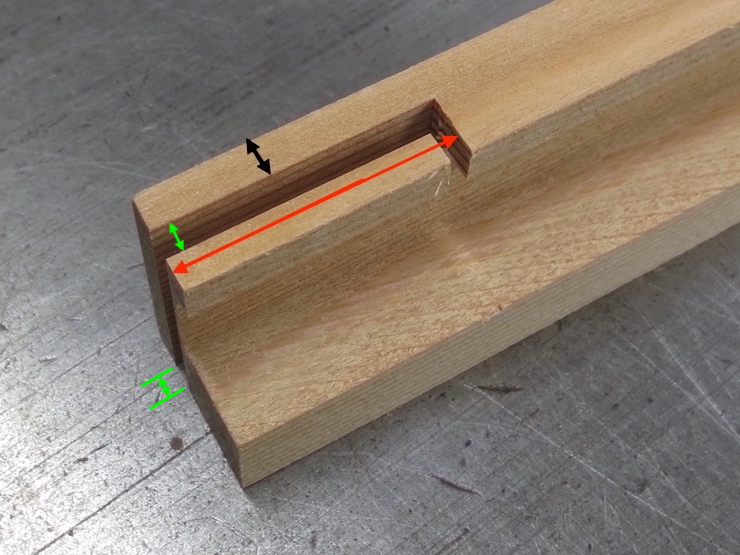
Next a small cut is made across the rim of the deckle. In the photo below the right end of the red arrow points to it.
The partly finished joint now looks like this. The dimension indicated by the black arrow is now exactly the same as the depth of the dovetail groove that was cut in the first half of the joint. The dimension indicated by the red arrow is the same as the width of the deckle parts. The slot shown by the green arrows has been widened to fit the previously shaped tongue on the opposite joint. Each of these finished surfaces have been tested against the appropriate parts of the other side of the joint. (The photos at the end of this post show how this is done).
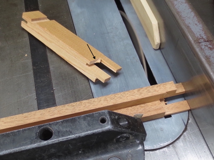
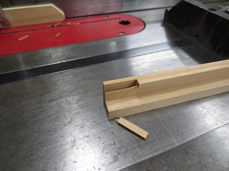
The next few steps rough out areas that need to be ‘cleared out’ to allow the dovetail tenon and lap tenon to be fitted more easily (in the next post). The first piece of waste can simply be broken off (above).
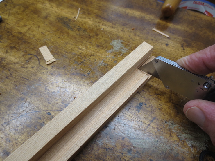
The next part can be cut off by hand with a utility knife. The shoulder near the tip of the knife will be trimmed to exact size later.
This cut is not exact either, but the first step in removing another waste area.
The same cut shown from below.
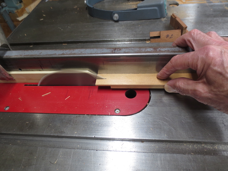
Another roughing cut is made. The height of the blade is set to cut across the waste without touching the ‘good’ part.
The two roughing cuts seen from above.
Now this part can be broken away on all of the pieces.
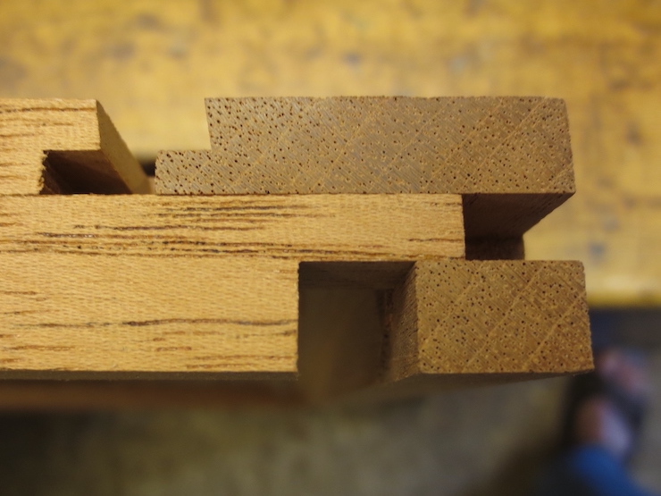
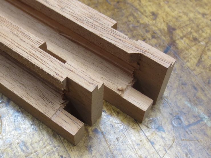
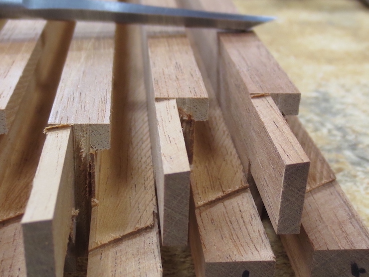
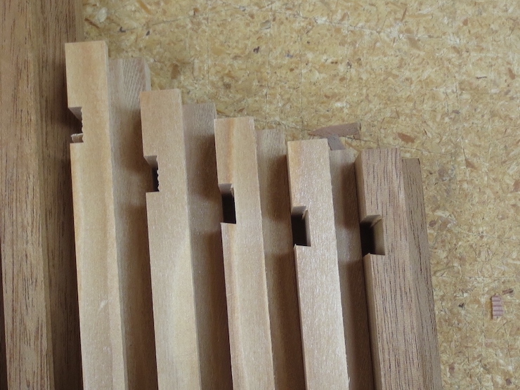
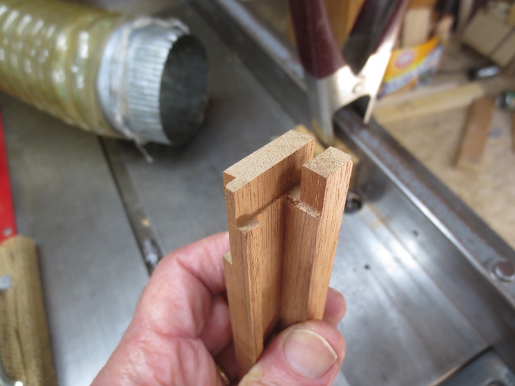
Removing the waste frees up the two tenons so they can be trimmed to fit into their corresponding groove and slot (covered in the following post). The sliding dovetail tenon (on top) is now the right thickness but needs to be trimmed on both sides. Parts of the lower tenon will be cut away to form a ‘tongue’ to fit into the slot prepared for it (see the previous post). Shaping this tongue creates a notch that will receive a lapping part, also shown in the previous post.
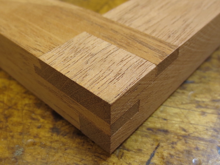
A completed example of the joint is shown for comparison above.
Testing the fit
As parts of the joint are shaped they are tested against the (previously finished) first half of the joint. The examples shown below have joints that have been completely shaped but serve to demonstrate the method.
The thickness of the sliding dovetail tenon is tested against the groove it must fit. If the parts are held firmly against a flat surface the mating surfaces should be able to slide past each other with little resistance. The surface that is being adjusted is indicated by the black “X”.
Likewise the other side of the slot can be tested against its mating surface. The green arrow points at the (hidden) surface that is being trimmed to fit against the surface indicated by the green “X”.
The cut across the rim of the deckle can be tested by standing the test piece on end. The red lines indicate the surface that is being trimmed to fit.
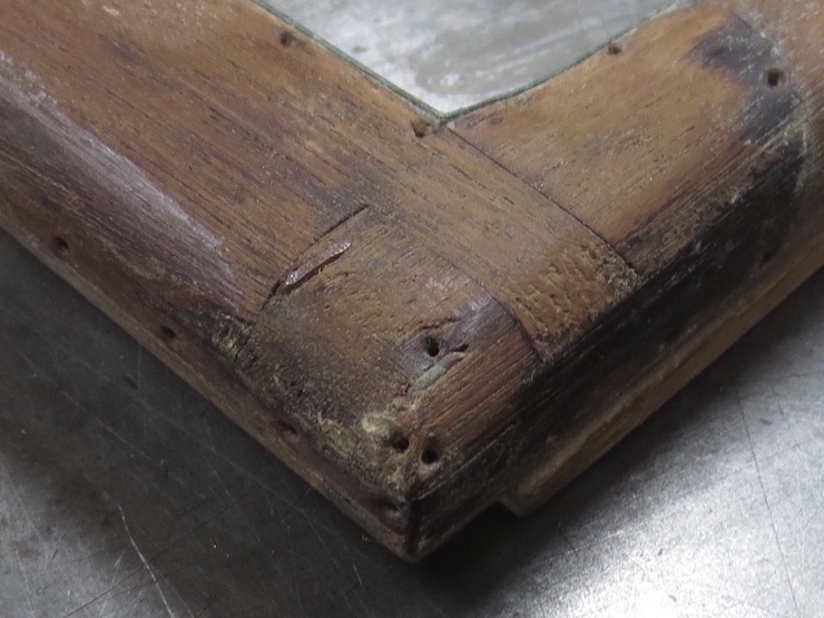
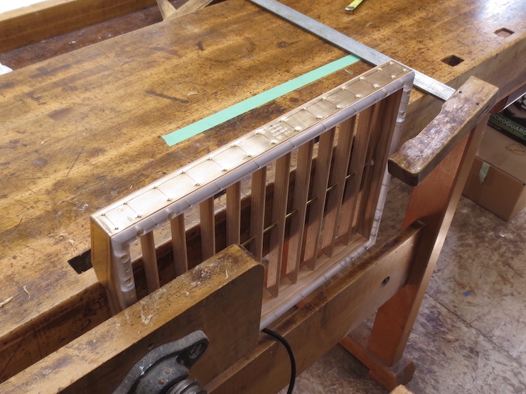
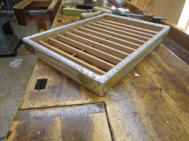
I will now try to explain the making of a traditional British deckle joint; mimicking the form but using non-traditional methods. Its elaborate form must have evolved from the necessity of creating deckles that could stand the abuse of being ‘slapped’ onto moulds hundreds of times a day while being constantly in an out of water. This joint can function without glue; water swells the parts, locking them together. Brass sheathing and a copper wire staple at each corner add additional strength.
When I took this deckle apart a few years ago I discovered that I had been making the joint wrong (or at least not the traditional way) for over 30 years without realizing it. I have since adopted this traditional form but use power tools and waterproof glue. The joint shown above was presumably cut by hand and shows a very high level of workmanship.
I create what I’ve been calling ‘the mortise side’ of the joint first. This is the part on the right in the photo above. It includes the groove of a sliding dovetail joint. My strategy has been to carefully make this half of the joint first, going through a series of steps using the table saw and router to shape identical features on one end of multiple deckle pieces. Then, using the same tools, the other ends are carefully shaped to make this second side fit neatly into the first side. I’ll explain the process here in four posts without getting hung up on dimensions. Later I’ll publish some standard dimensions and some musings on how the parts of the joint function.
These joints are made to connect in ‘pinwheel’ fashion. All four of the wooden pieces that make a deckle include both sides of the joint, one at each end. This eliminates the need to create opposite (mirror image) forms of the joints. The old deckle that I took apart to examine did not use this strategy but I have read that the pinwheel approach has been used historically.
Most of the waste is roughed out on the table saw to start the dovetail groove. I don’t like ‘hogging out’ with router bits, preferring a slow and gentle approach. The cut at the left side of both pieces is a finish cut. It will form one side of the dovetail groove, the non-slanted side.
The two parts on the left have been roughed out. On the right three parts have been further refined by one pass over the dovetail bit, creating one slanted face and leveling the bottom of the groove. (There’s nothing sacred about the 9 degree angle used; it looked good to me and dovetail bits are available with this angle).
Here’s the set up for routing the angled face and flat bottom of the groove. The block behind the deckle part has true right angles to support the part while it is pushed through.
After all of the pieces have been trimmed the fence will be moved a little closer to finish the bottoms of the grooves.
On the back piece a second pass of the router has cleaned the groove up right to the edge, finishing the groove. It might be more accurate to call this a ‘half dovetail’ groove since only one side is slanted. If you imagine the sliding dovetail ‘finger’ or tenon that will be shaped to fit the space (vacant here) you can see that the angled edge of the sliding dovetail would tend to force the parts of the deckle tightly together when the tenon swells from being wet. One end of this ‘dovetail’ edge lies directly above the inner corner of the deckle where two parts of the narrow rim will come together. (The four parts of the deckle form a rectangular ‘wall’ that encloses the pulp to define the edges of paper formed there. The rim is the part of the deckle that rests on the wires of the mould). It can’t be an accident that this part of the sliding dovetail is positioned just here. Its purpose must be to keep the rim parts aligned, helping to insure that they press evenly against the wires of the mould to make clean deckle edges.
The dovetail bit is left at the same height for the next cut; making another 9 degree face parallel to the inner edge of the deckle part. This second angled face also lines up with the deckle rim but at 90 degrees to the first one. When both sides of the joints are completed and put together the wedging action of both slanted faces will work to keep the parts aligned, especially at the inner corner.
A scrap of wood makes a temporary fence so the dovetail bit can be partly hidden beneath to route a narrow margin along the edge of the deckle part.
Each part is pushed against the stop, then pivoted against the temporary fence (in the direction of the short arrow).
Then it is fed into the cutter (in the direction of the longer arrow) to finish the cut.
This cut has been made in two stages; the fence being reset before the final cut. If you imagine the nearer ‘dovetailed’ surface extending across the gap to meet the other you see that they intersect above the place where the inner corner of the deckle rim will be.
Making the Slot
Next a slot is made which will receive a ‘tongue’ from the adjoining piece of the deckle. The slot is cut to the same depth as the thickness of the mould frame.
I use a leftover test scrap from a mould to scribe the top of the cut to prevent chip out.
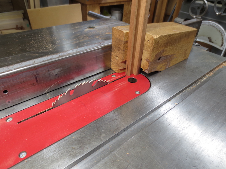
To make these cuts the deckle parts were stood up in the wooden right angle block. (Described in the previous post; this tool appears again two photos down). Two saw cuts create the sides of the slot; both are finish cuts. The waste between them is cut out in another pass. When making deckle joints I make sure to have a few practice parts; short scraps of the same deckle stock that have been processed exactly as all of the other parts. These are used to make test cuts and necessary adjustments to get everything right before running the other parts through each step.
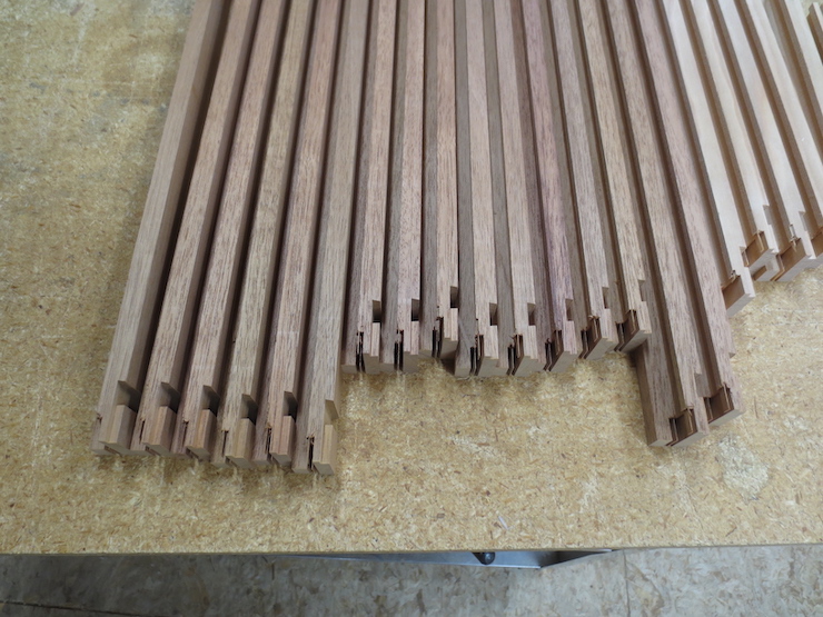
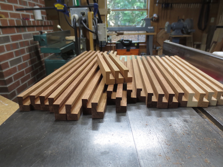
Twenty parts are needed for five deckles; there are extra test pieces at the far right. Making the parts identical (except for length) makes this painstaking method of cutting joints worthwhile and ‘cost effective’.
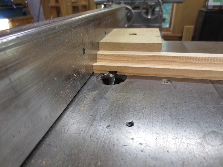
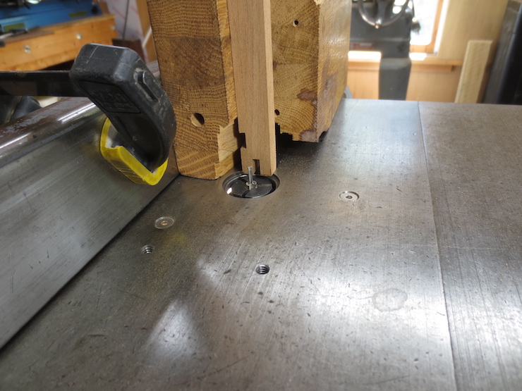
This 1/8″ diameter bit is being used to machine a flat surface at the bottom of the slot. This is the first illustration of the ‘right angle block’ being used to stand deckle parts upright. Many operations are done with the parts lying flat on the table; others depend on the block so the ends can be machined.
You can see the bit, the slot and the scribed line. It looks like the deckle part would fall into the opening in the table but the ‘stop’ (the yellow clamp pad) will stop the motion before that can happen.
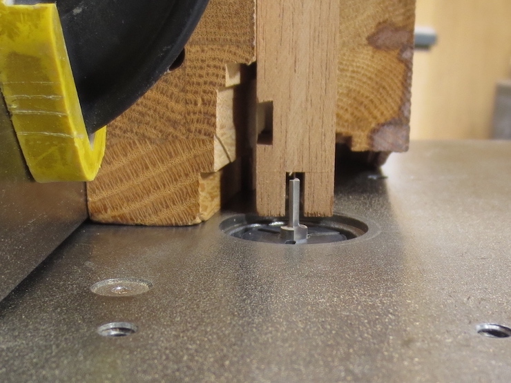
Another view of the right angle block and the same operation.
The bottom of the slot has been routed from one side. When multiple deckles are being made all at once it can be worthwhile to make small adjustments. There is always a little bit of hand work at the end, but reducing this saves time. If I was making one deckle only (with four identical parts) this particular operation might not be worthwhile. The bottom of the groove might be more easily cleaned up with a sharp chisel.
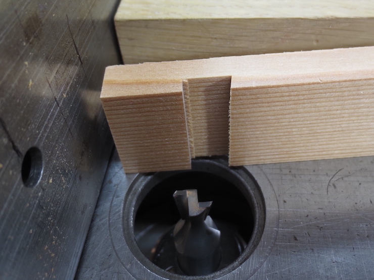
This end of the slot still needs trimming.
The slot is now finished after trimming from the other side. The part was turned 180 degrees in the right angle block and the fence re-adjusted to guide the part over the router bit.
Trimming the Lap to Width
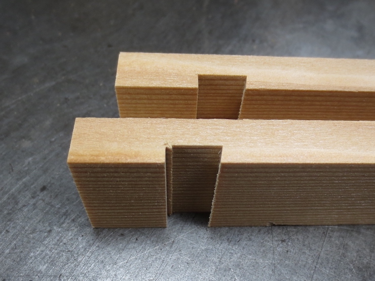
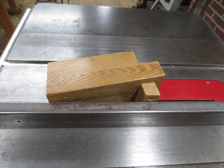
Cutting the groove has left a protruding tenon that will lap over a recessed area to create yet another mechanical connection between the two parts of the joint; a ‘lap joint’. Trimming away the waste (indicated) will complete this half of the joint. The waste can either be routed away, or trimmed on the saw as shown below.
This deckle joint is from an earlier batch. I used the hollow ground saw to trim this part of the lap to its final width. The height of the saw blade must be adjusted to trim the face of the joint without damaging the upper part of the joint (face down and hidden here). The radius of the saw cut extends out onto the inner edge of the deckle. If the deckle and mould have been sized correctly these visible cuts will be trimmed away (or nearly so).
Here is another way to do this with the router and 1/4″ diameter bit. The wooden block at the left is a stop. The deckle part is pressed down on the table and against the fence while pushing it into the spinning bit.
This leaves a ragged edge but this will be trimmed off later when the deckle is fitted to the mould.
This half of the joint is now complete. The narrow deckle rim on the left and the inner edge where the deckle laps over the sides of the mould are still rough but will be trimmed later as the deckle is being fitted to its mould.
The right side of the joint has been completely formed on all twenty parts of this batch. The next few posts will cover the process of making the mating form of the joint (shown on the left here).
A brief review of the tools I use to create this unique and elaborate joint. Most of these tools have been used before when making the mould frame and ribs.
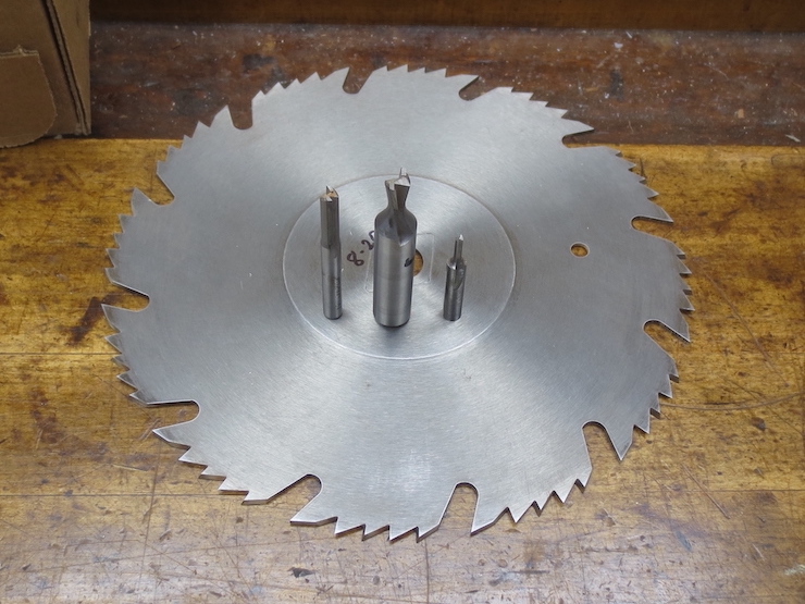
Left to right: a 1/4″ straight bit, a 3/8″ by 9 degree dovetail bit, and a 1/8″ straight bit, all to be used with the router mounted under a wing of my table saw. The hollow ground planer blade has been used all along for making the moulds; freshly sharpened, it will be the only saw blade needed for cutting the deckle joints.
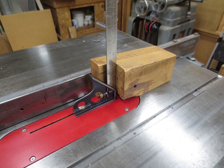
This wooden block has served me well for over 40 years. It has true 90 degree angles here…
…and here so that pieces held upright in the block can be accurately cut with either the saw or router.
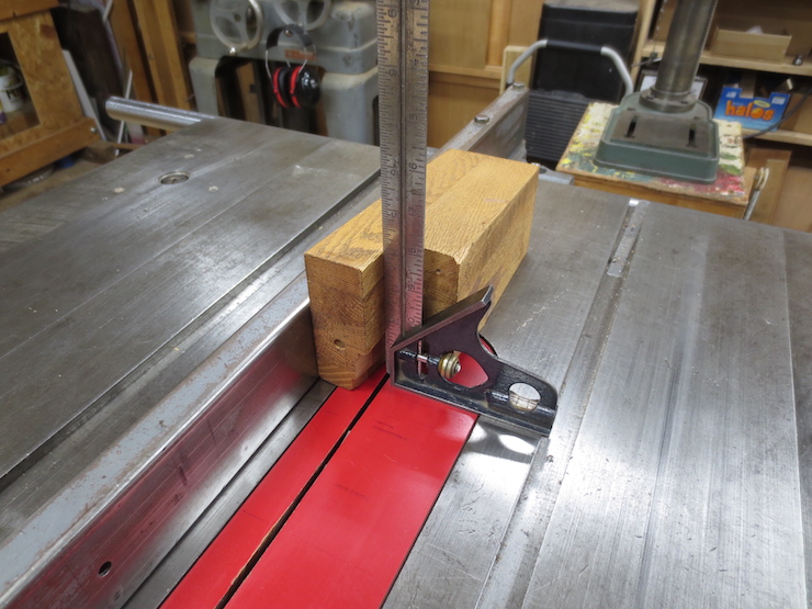
Adding the small block on the right changes the angle from parallel (to the fence) to 9 degrees. This matches the angle of the dovetail router bit so the sliding dovetail part of the joint can be sawn to fit the routed groove.
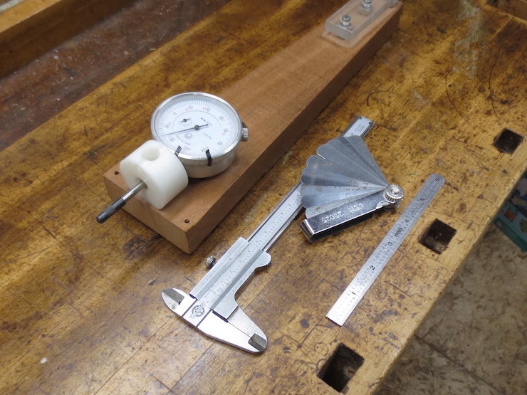
This shows the end of the dial indicator fixture that is used for making lateral adjustments. Also shown are a set of shims, a 6″ vernier caliper and a 6″ rule.
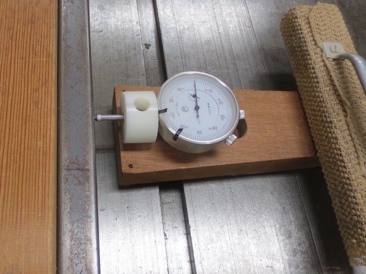
Using the dial indicator for making very fine lateral adjustments; in this case adjusting the table saw fence. It has been ‘zeroed out’ prior to making the desired adjustment. A few tries will be needed to get the fence just right (‘nudging’ and re-tightening the fence each time) but since the fixture remains stationary all the while it will show when the fence has been successfully re-set.
The other end of the dial indicator fixture is used for making vertical adjustments like this. The flat lower end of the plunger has been ‘zeroed out’ while resting on the table. Then it was lifted to rest on the router bit to allow the cutting height to be adjusted.
These pieces have already been put through some preliminary steps. For a review of these see the early post about seasoning and preparing wood. You may also wish to review the techniques used earlier to prepare the frame stock for the moulds, some of which will used below to prepare the deckle stock.
Using the jointer two adjacent sides of all the pieces are made perfectly straight and square to each other. These two finished surfaces are indicated here by red. In the finished deckles the narrower of these will form the vertical sides of the opening that defines the paper’s edges as sheets are formed.
Next the two sides opposite are machined straight and square. Using the dial indicator with the table saw fence allows these deckle pieces to be cut to precise overall dimensions (width and height). These two surfaces (indicated in green) are left rough, straight from the rip saw. They may look ‘rough’ but are functionally very precise; accurate enough to be used as reference surfaces when cutting the joints. These rough surfaces will disappear later, being machined away as the deckle is shaped to its final form.
Next the top of the channel and the inner edge of the rim are machined to produce the final surfaces there. These are outlined in red in in the two pieces shown below. The piece on the left is only partially machined to better show the process above.
Some surfaces (outlined here in yellow, blue and white) will be machined later, after the joints are finished.
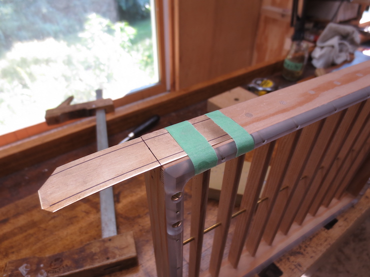
The next step is to trim the deckle pieces to exact length in preparation for cutting the elaborate deckle joints.
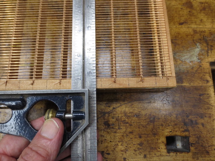
After all the deckle pieces have been trimmed square at one end the measuring beam is used to mark them for length. You may recall that this same beam was used to mark the lengths of the mould frame pieces. Using the same measuring device for both mould and deckle insures a good fit between them.
The stop (at the white arrow) is set so that the hollow ground blade cuts right at the scribed mark. Three 12″ x 18″ moulds are part of this batch, needing identical deckles. The stop is used to make all six of the long pieces the exact same length (then reset to cut all six of the shorter pieces). If only one mould of a given size is being made, opposite deckle parts (either both sides or both ends) can be clamped together and cut without using the stop. The important thing is that the two opposing sides of any deckle are cut to the exact same dimension.
To calculate the lengths of the deckle pieces “A” + “B” is added (twice) to the intended opening of the deckle “N”. For my standard moulds the deckle overlap (A) is 3/4″ and (B) is 1/2″. This makes the total width of the deckle pieces 1-1/4″. Twice this equals 2-1/2″. Thus the short sides (or end pieces) for a deckle with a 12″ x 18″ opening should measure 14-1/2″ long and the long sides (the front and back pieces) should measure 20-1/2″. The clearance between mould and deckle shown at “C” has already been accounted for in the overall dimensions of the mould.
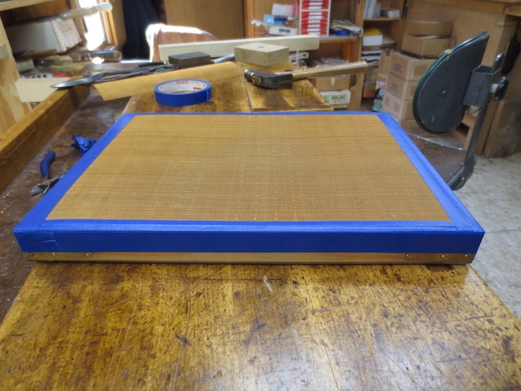
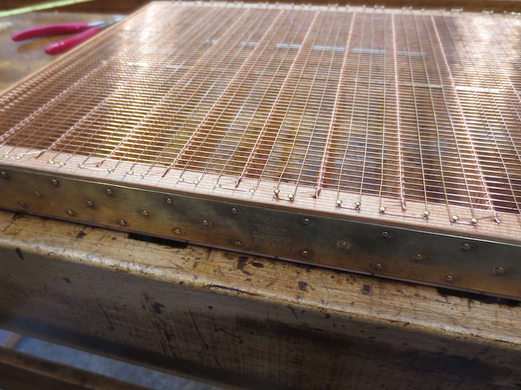
A piece of phosphor bronze ‘wire cloth’ is cut to the size needed. I have always used phosphor bronze for this though it is more difficult to find than ‘plain’ bronze or brass. Either of these would likely work well but are less durable. Paper mould wove facings typically are made from wire cloth in the range of 40 to 50 wires per inch, though I have seen finer. The wire cloth I have used was purchased from a Dandy Roll manufacturer. This wire seems to use a slightly heavier wire for a given mesh size than some brass and bronze wire cloth I have found.
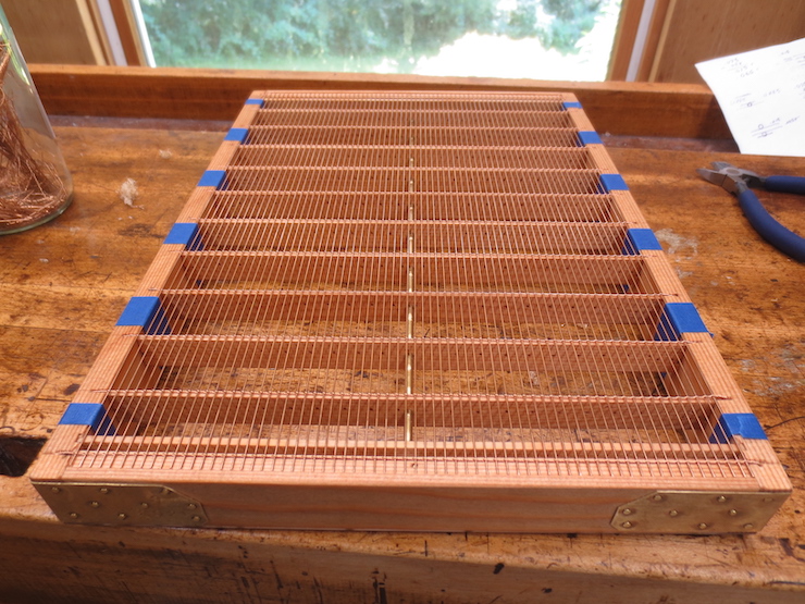
Care is taken to align the weave of the wire mesh with the grid wires since they must follow the ‘grooves’ in the wire facing. A few brass escutcheon pins hold the wove facing in place.
The tape protects the edges of the wire so it won’t get damaged while the mould is being sewn.
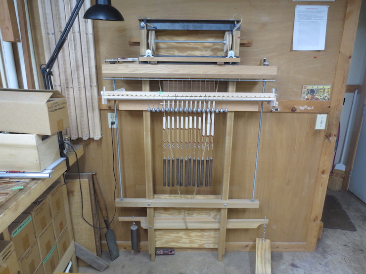
The sewing frame is adjusted to hold the mould a bit higher so that the row being stitched is near eye level. A piece of paper hangs from the cross bar and is backlit. The room can be dim. It is easiest to sew by seeing the wire in silhouette.
Another view. I wear a #4 optivisor while sewing the wove facing.
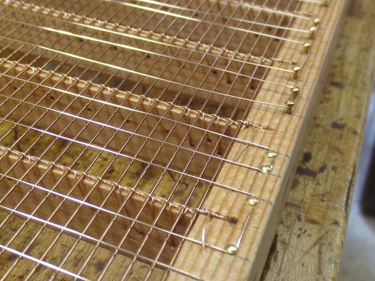
This is what the completed stitching looks like. The sewing wire crosses under* three laid wires (of the backing) between stitches taken over* two wires of the facing. The stitches are staggered, offset by one laid wire with each new row. This creates a diagonal pattern to the stitches. At the ends (not visible here) the stitches are identical for all rows (not staggered) and a ‘knot’ is formed, securing the sewing wire and tying the facing securely to the last ‘free’ laid wire of the backing. (This ‘free’ wire is actually the second wire, the first lies right next to the wooden frame.)
You can see that the two outer grid wires are sewn while the middle one ‘floats’, though it is held quite firmly in place between two layers of wires. I sew wove moulds with a .008″ diameter soft phosphor bronze wire. Each row is started from the middle of the mould, sewing from middle to right with one end of the wire and then middle to left using the other end. This makes it easier (less wire to handle) and keeps the wire fresher. Each sewing wire takes the form of a long spiral as it travels the length of one grid wire, passing under three laid wires, then coming up over the top and crossing two wires of the wire cloth, then passing once again under the next three laid wires, etc.
*Under” and “over” here refer to the mould in the upright position, not upside down as in this photo.
Four rows of stitches have been completed. You can see them just to the right of center.
To the left of this row of stitches you can just see a rib below the mesh. To the right you can discern the middle (un-sewn) grid wire nesting in a groove created by the wires of the mesh facing.
To keep the stitches as inconspicuous as possible they are sewn in a certain way. As a sewing wire crosses two wires of the mesh on top of the mould it crosses the first wire at its low spot. Then it takes a slight diagonal to cross the second wire at its low spot. As the row is stitched the openings that the wire passes through are chosen so that the sewing wire’s diagonal path crosses over the top in the same direction as the general path of the wire. If the wire is forced ‘backwards’ by passing through the wrong two openings it will protrude a little more and make a bigger ‘bump’ on the top of the mould.
This process is not as difficult as it sounds. When the mesh is viewed at an angle the square openings change to look like rows of alternating trapezoids, some pointing down, some pointing up. Once you figure it out you can use this trick to easily put the stitches in the right spaces.
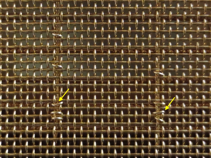
You can’t choose the openings when making the last three stitches to form the ‘knot’ so this process can’t be followed here. Visible in the photo are two stitches that were forced to cross ‘backwards’ by the low spots in the mesh, reversing their angle. These stitches (indicated by yellow arrows) ‘break the rules’ and as a result don’t lie quite as flat. It doesn’t matter in this case because this part will lie under the deckle and paper won’t be formed here.
A view of of the ‘knot’ from above. To form the knot the sewing wire passes down through the ‘hole’ at [A] and comes up at [B]. It then crosses over two wires on top and down through [C] before passing back under to come up again at [D], crossing under the laid wire in the process. The sewing wire goes down at [E] and ‘reverses course’ to pass up at [F]. This time the wire is left a little loose. After the wire is pulled down through the mesh at [G] the end is poked under the previous stitch (between [E] and [F], not visible here) before passing up through [D] once more. The end of the sewing wire is then pulled which tightens the stitch that was left loose. This has the effect of trapping the wire near its end. The excess wire (represented by the curved red arrow) is pulled and rotated until it breaks off just below the surface (at the tip of the yellow arrow). The wire always breaks in the same place just below the surface due to the rotating action. This weakens the wire in this spot before it is pulled hard enough to break. Note that the stitches of the knot are directly adjacent (on both sides) to the last ‘free’ laid wire which is indicated here with green dashes. The knot ‘lashes’ the mesh facing down to the laid wire as well as securing the end of the sewing wire.
[
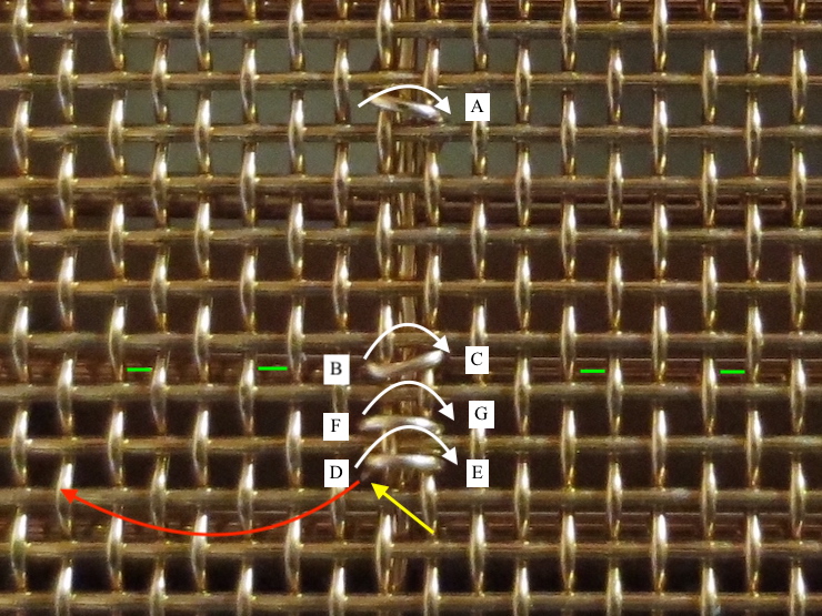
A view from below showing the sequence used to form the knot. The last stitch before the knot [A-B] is always located in the third space (located between the third and fourth laid wires) from the wooden frame.
Starting at [1] the sewing wire enters the opening right next to where the laid wire and the grid wire intersect. It passes over two mesh wires in the usual way and comes back down* through [2]. It then passes under* the laid wire and skips over a mesh to pass through the opening at [3]. After crossing the same two mesh wires on top it comes down through space [4] and ‘reverses course’ to pass through space [5], right next to the laid wire. For now this new stitch is left loose. This is so that after the wire is fed down through space [6] it can be poked through the loose stitch before passing one more time up through space [3]. You can see that the very end of the sewing wire is now held in place by the previous stitch. The knot has been completed; now the sewing wire is pulled tight and the end is rotated and pulled until the wire breaks. The red arrow points at the broken end of the wire.
*Once again keep in mind that in this photo the mould is upside down and that “over”, “under”, “up” and “down” may seem reversed.
In this photo the green arrows show the location of ‘knots’, where ends of the sewing wire are secured, straddling the last free laid wire, which can be seen beneath the wire mesh if you look closely. The yellow arrows show the row of stitches that fall in the space between the same two laid wires of the backing. The black arrows show the locations of ‘regular’ stitches, the stitches that secure the rest of the wove facing to the laid backing/grid wires. These are placed in a diagonal pattern visible here.
I hope this gives a fairly complete description of this process. I may have left out some details which would have helped explain things more clearly. Let me know if this is the case in this or any other post; I may be able to ‘fill in the gaps’ with more photos or text.
A wove mould’s backing layer is similar to that of a laid mould. I’m not sure why but wove backing wires are usually more closely spaced than those used for laid moulds. At least this was the case with the moulds I was able to examine when getting started years ago.
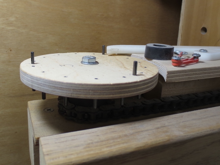
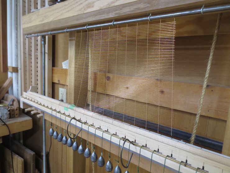
The counting wheel of the loom is changed to make a 7.8 wire per inch wire spacing. The wheel has 3 pins. The twin lead screws (you may remember) have 13 threads per inch so dividing by 3 gives 39 increments per inch. I turn the crank to count 5 of these ( audible as 5 clicks) before adding each new wire. (39/5 = 7.8) The straight (laid) wires used are the same diameter as those used for laid backing; .0254″ diameter. The chain wire is smaller; .013″ diameter.
The first few inches have been ‘woven’ (twisted or twined might be be a better term) and a row of (white) wire spacers is being removed to free up more chain wire. The process of using the loom is covered fully in other posts and in a video.
The backing for this A4 wove mould is completed. The weights will be removed prior to cutting it off of the loom.
The bottom is cut off first.
The wove backing is ready to be fitted to the mould.
The ends of the laid wires are recessed in ledges at the ends and the chain wire rests in a groove there.
The backing is fitted. After adding tape at the ends and along the top to protect the wires the backing will be ready for sewing to the ribs.
A wove mould is sewn in two steps. First the backing layer is sewn to the ribs as shown here. In a later step the wove facing will be sewn to the backing.
The sewing process is very similar to that described earlier for laid moulds. A stitch is placed in every third space (pre-determined by the hole spacing) and the sewing wire is heavier; the same stock as used for the chain wires.
The backing has been sewn to the ribs and the mould is ready for the next step.
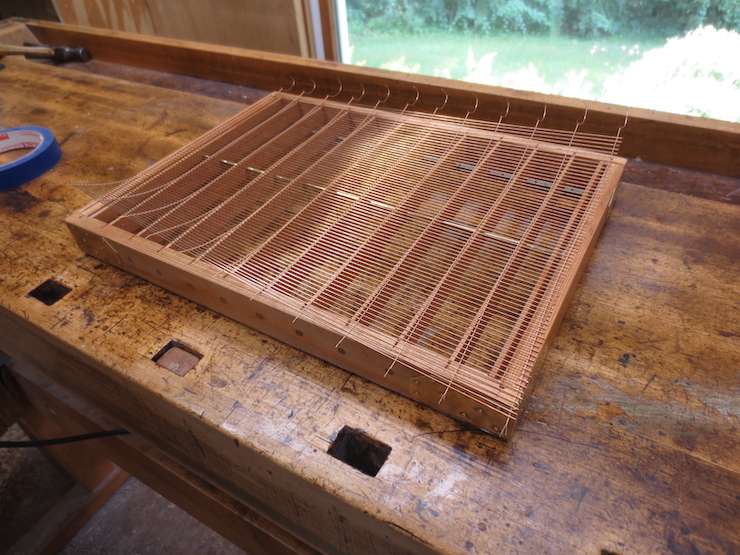
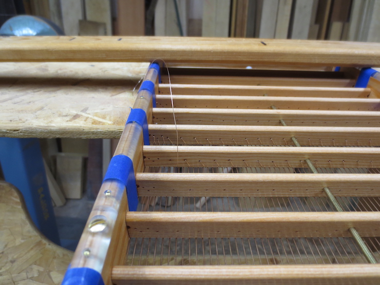
The next step in making a wove mould is to add a wire that passes back and forth across the top to form a grid. This will support the fine wire screen that will be used as a facing.
In the photo above the grid is nearly complete; below are the steps needed to create it.
The spaces between the ribs are divided exactly in half and marked with pencil. Then these spaces are also halved.
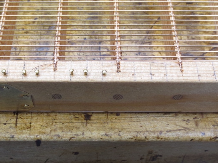
Very small brass nails are hammered part way in for the grid wire to wind around. Notice that the pins are placed to one or the other side of the marks, depending on the course of the wire. This is so the wire will be located right on the marks. These nails are #19 escutcheon pins.
The .015″ diameter wire will be pulled off the spool as it is wound back and forth across the face of the mould.
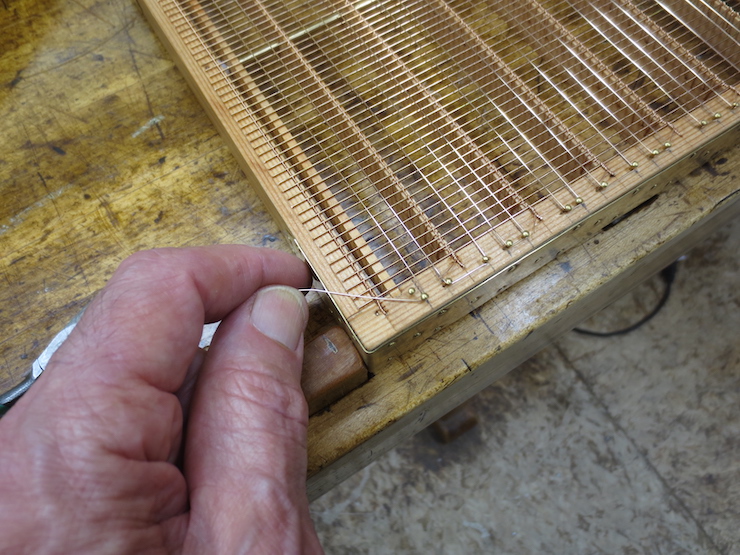
Winding the wire. The wire was anchored at the far corner by wrapping it around an extra pin which was then driven down flush with the wood.
The other end the wire is anchored the same way.
As the nails are driven home the wire tightens and straightens.
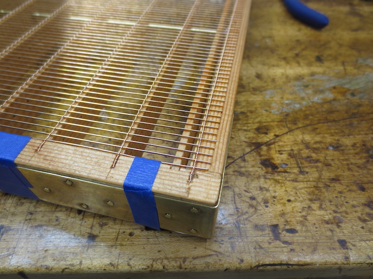
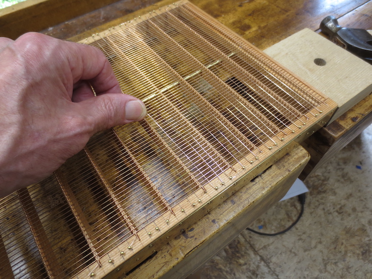
A closer view. This is the first mould in which I have used three equally spaced grid wires between ribs. The two outer ones will be stitched in place as the wove facing is sewn down. The center wire is not sewn in place but is held in place by pressure between the laid wires of the backing and the underside of the wove mesh facing. The pressure pushes it into one of the many grooves formed by the warp and weft of the woven wire facing. The outer two grid wires are also pushed into grooves but are sewn firmly in place. I have seen this pattern on most wove moulds. Previous to this I have made wove moulds with only two grid wires between ribs, both sewn. (Perhaps I didn’t trust the ‘loose’ wire to stay in place.)
Skipping ahead a few steps to show how the grid wires will nest in ‘grooves’ created by the zig-zag warp and weft of the wire mesh facing. A single un-sewn grid wire in the center is held in place simply by being squeezed between the laid wires and the wove facing. It is flanked by two grid wires which have been locked in place as part of the process of sewing the wove facing to the backing/grid structure.
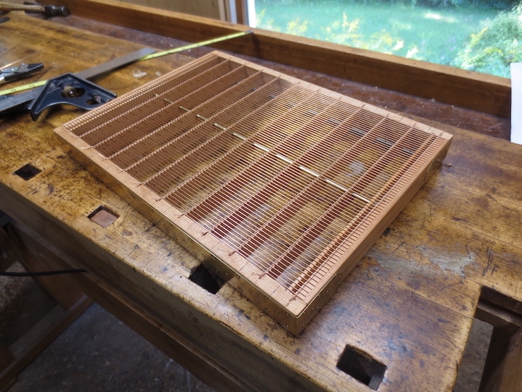
The grid is complete and the mould is ready for its facing.
Many moulds made for use in commercial mills are fitted with metal sheathing. Since most of the moulds I make aren’t used this way I rarely use sheathing.
The mould used as an example here is a small wove mould made entirely of western larch, both ribs and frame. This choice of wood is an experiment. The purpose of making it a wove mould was to add that structure and the necessary processes to this series of posts. Sheathing was added to this mould so that that topic could also be included.
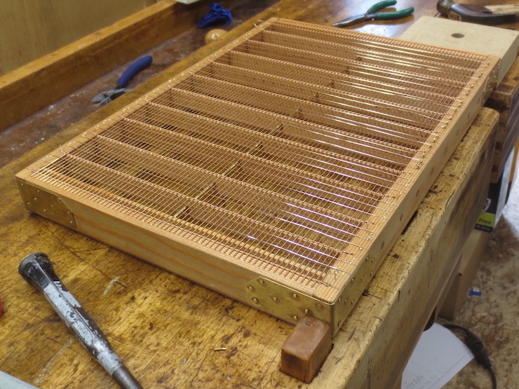
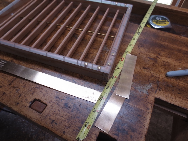
The sheathing is .017″ cartridge brass. I have a roll that is soft (annealed). Brass shim stock is easier to find but often too stiff for this purpose. It can be annealed with a propane torch, though.
Typically the sheathing covers the entire front of the mould, wrapping around the corners. The other two corners have separate shorter pieces. Sometimes the sheathing is not symmetrical which puzzles me. Was this done for a particular purpose?
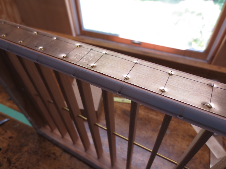
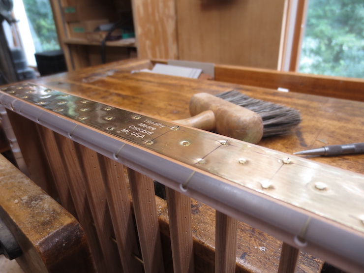
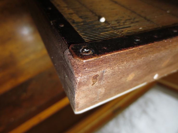
After the brass is nailed in place with 1/4″ brass escutcheon pins the metal is burnished down and the nail heads filed flat.
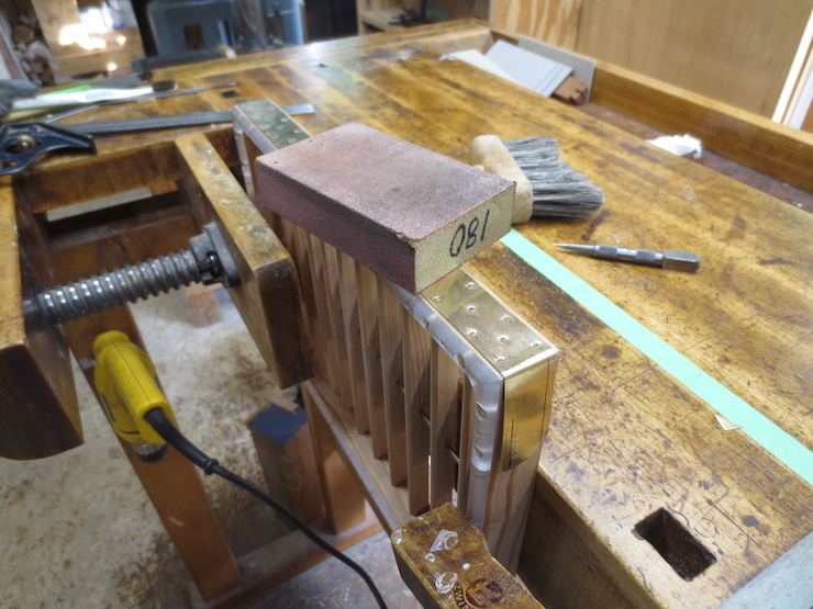
I ‘polish’ them with a sanding sponge to round off any sharp edges and make it look better.
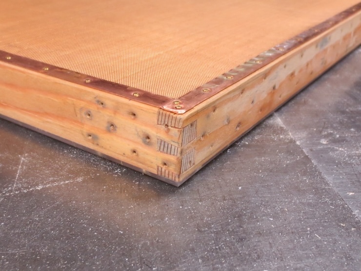
The front has been finished.
The bottom side of the partially sheathed mould.
The remaining two corners each have a separate piece of sheathing.
The purpose of the sheathing was probably partly to protect the wood from wear and partly to help hold the mould frame together in times before waterproof glue was available. It may have been partly to protect the vat person’s hands; I had a conversation with the man who used the moulds shown below in which he described the substantial calluses that he developed. The wood suffered too, being worn to a fuzz in the areas gripped during sheet forming.
Perhaps this mould would have benefitted from metal sheathing.
The wood is worn away from use.
The mould in these last photos is one of the few I’ve made that have been used in heavy production. These were used in pairs more or less continuously to produce about 500 to 750 sheets per day.
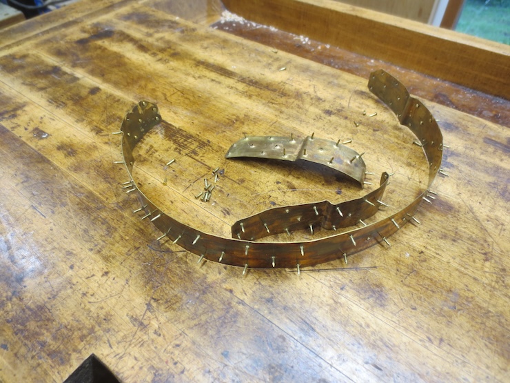
Removal of Sheathing
This mould was made of Western Larch as an experiment. It is the only one I’ve made. I fitted the deckle to the mould with the usual amount of looseness. Much later when we finally used it the deckle got stuck to the mould when the parts got wet. I opened up the deckle a bit but it still stuck so I pulled off the brass sheathing, which was surprisingly easy. Clearly it is important to account for the larger amount of swell when using Larch to make moulds.