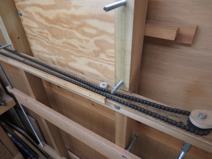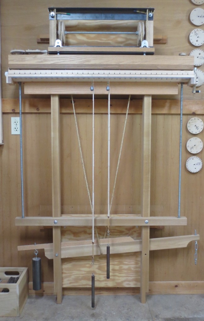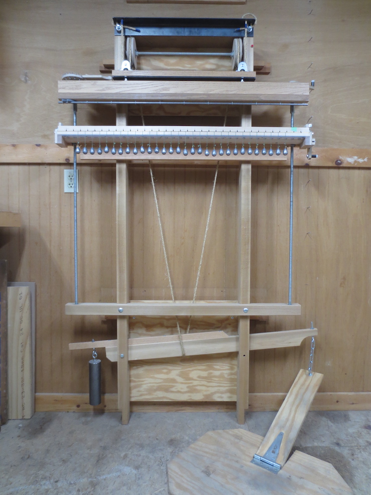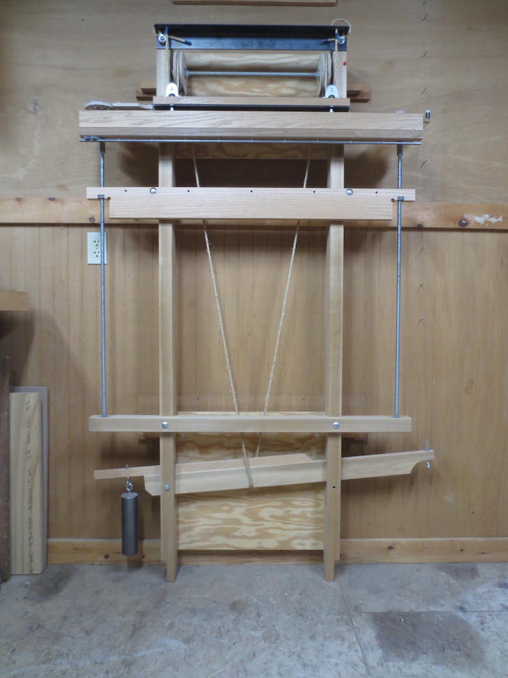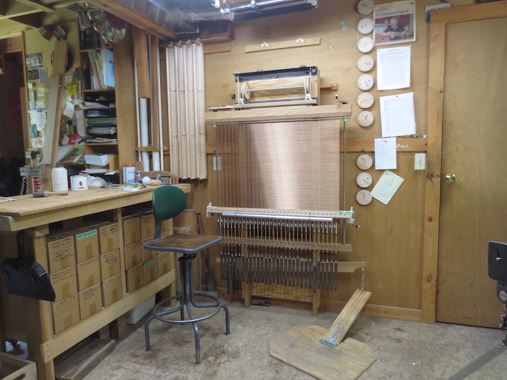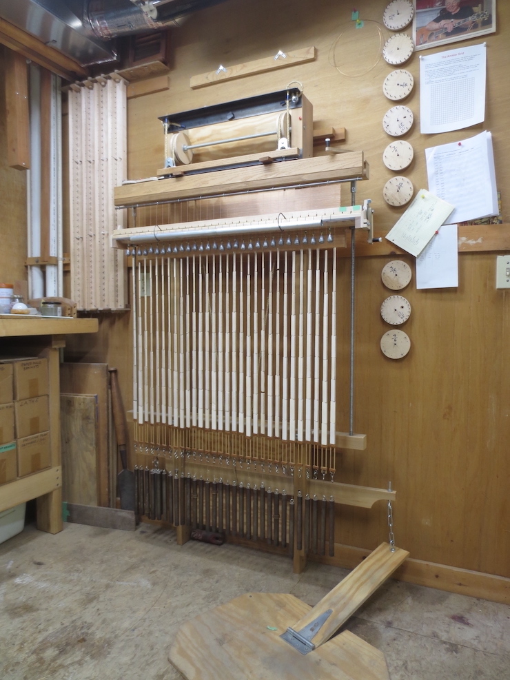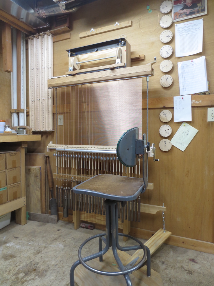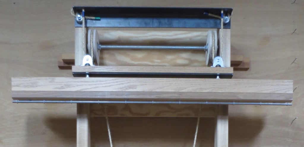
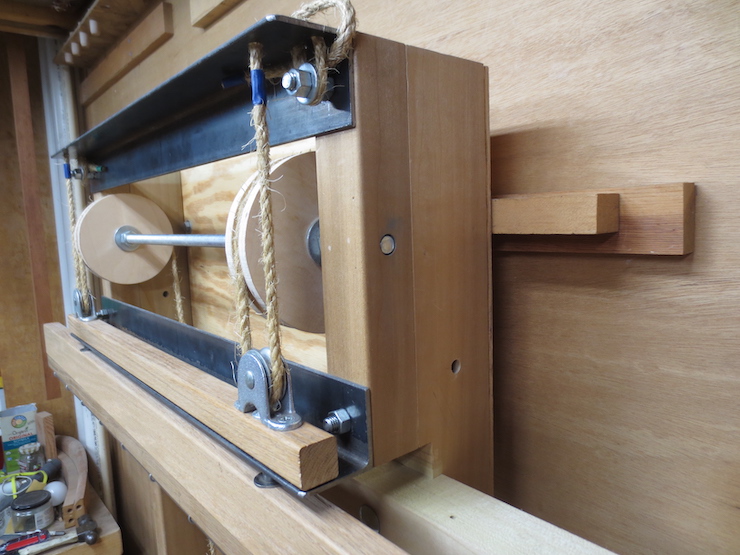
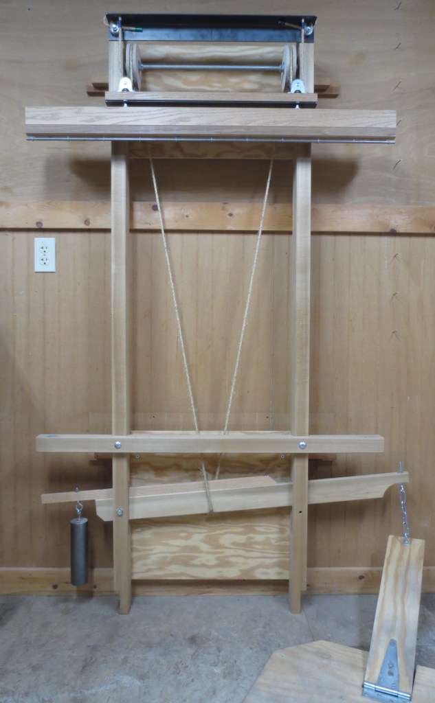
The purpose of the lift mechanism is to repeatedly lift the wire facing so that laid wires can be added at the bottom. A treadle and lift lever (not pictured, at the bottom of the loom) pull down on the middle of a “V” of rope. (The top ends of the V are visible here.) The ends of the rope pass up and over a pair of large wooden pulleys. The wooden pulleys reverse the rope’s direction to lift two smaller steel pulleys attached to the short upper lift beam. This raises the entire lifting beam assembly one half inch. Attached to the bottom of the long lower lifting beam is the steel lifting rod. Weighted wires will hang over this rod to form chain wires when making a laid facing (or backing) on this loom. When pressure on the treadle is released the rope relaxes and the lifting beam drops back to its lower position.
Large Wooden Pulley Assembly
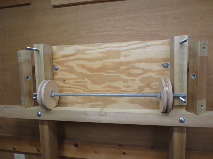
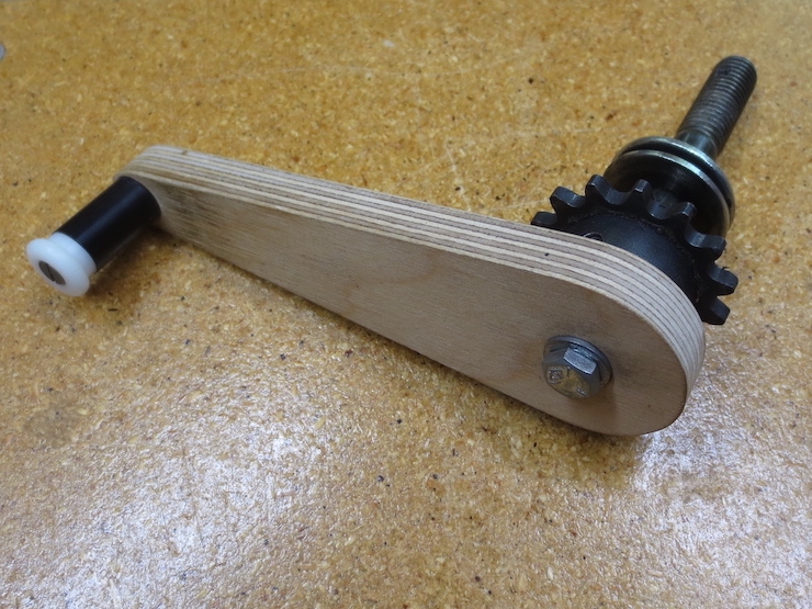
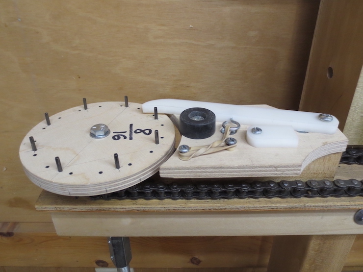
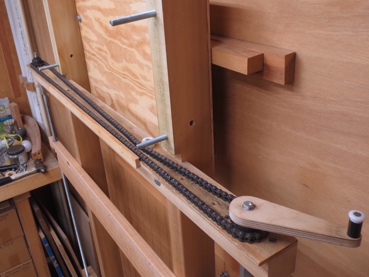
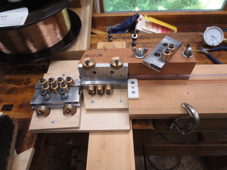
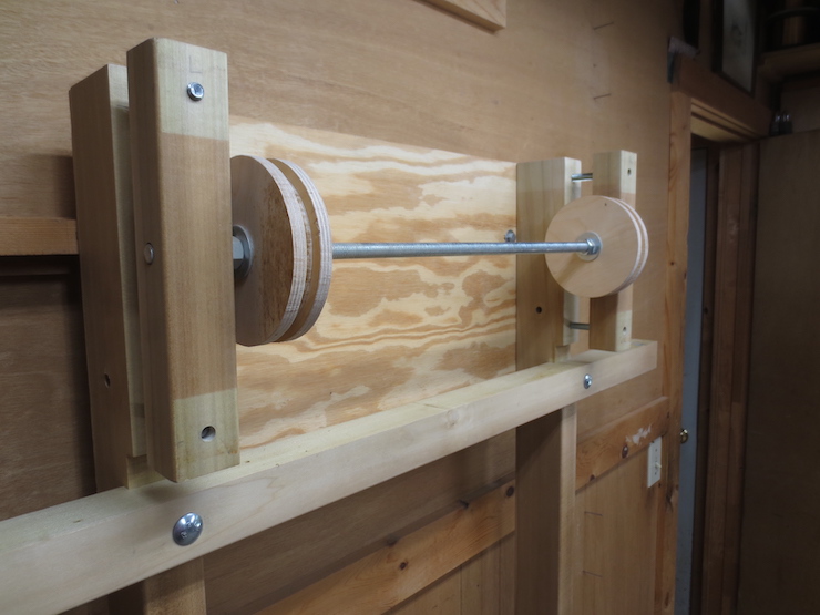
Two large pulleys are made from layers of birch plywood. Each one is a sandwich of one smaller disc and two larger ones. Steel washers and nuts are added to both sides of each pulley to bind all of the parts tightly together. Both pulleys turn together as a unit and only rotate (back and forth) a few degrees, about an inch at their perimeters.
Loosely placed at the sides of the cross-piece above are two wooden blocks which attach the pulleys to the frame. Each is fitted with a nylon bushing for the threaded rod/axle. It might seem sub-standard to use threaded rod as an axle and nylon bushings as bearings. But it is a simple solution that has proved to work very well. The original pine loom had no bearings at all and worked for decades without any problem. Nylon bushings are more durable than pine and have the advantage of being easily replaced.
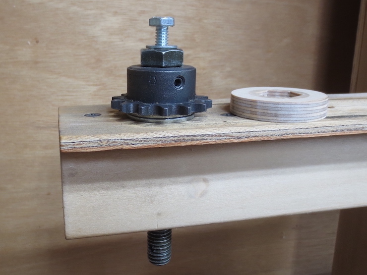
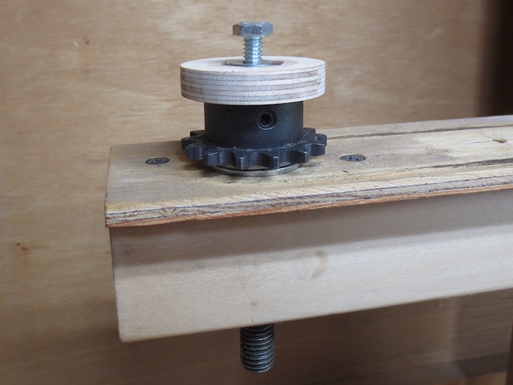
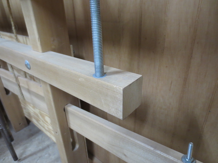
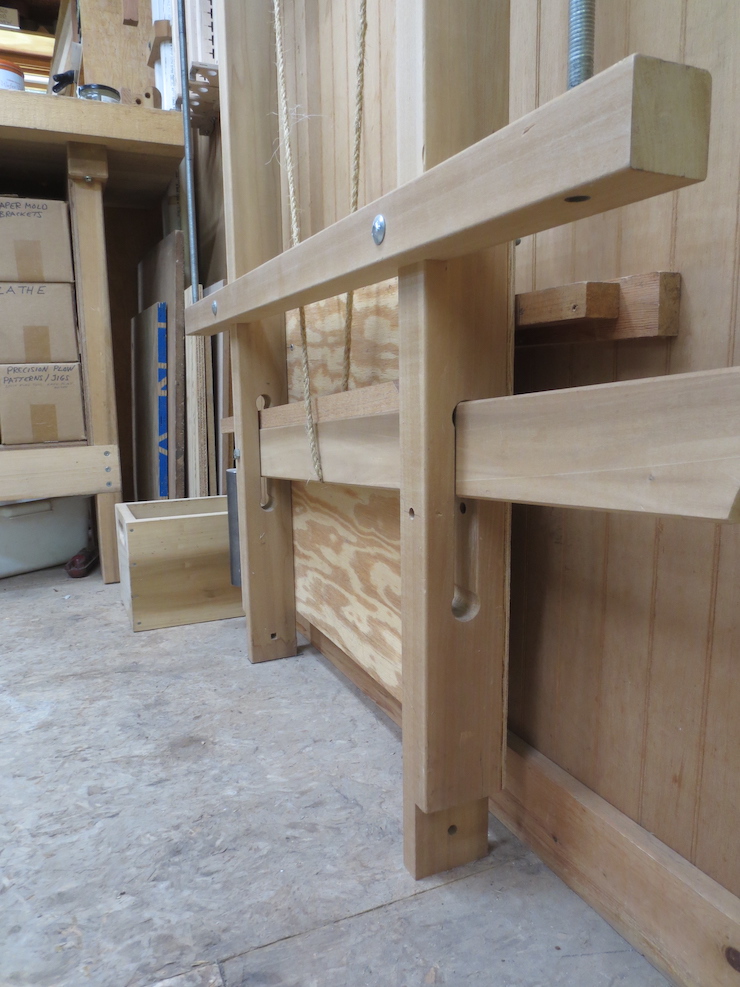
The wooden pulley assembly in the process of being slid into place over the four carriage bolts that secure it to the frame.
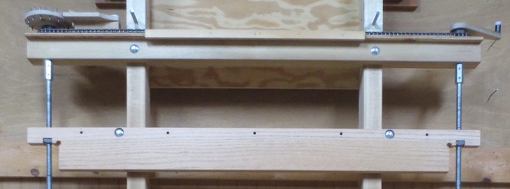
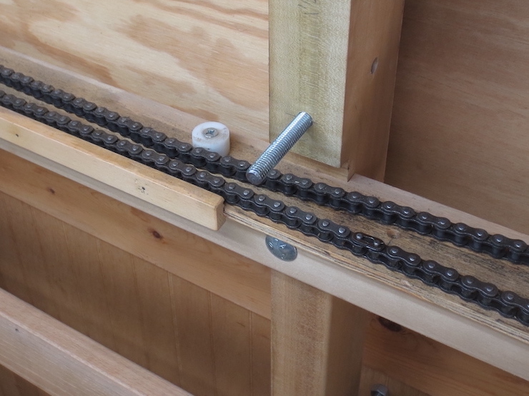
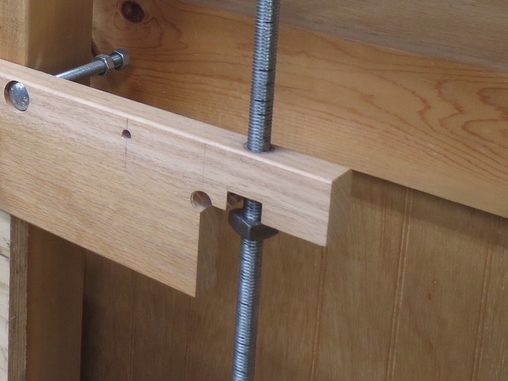
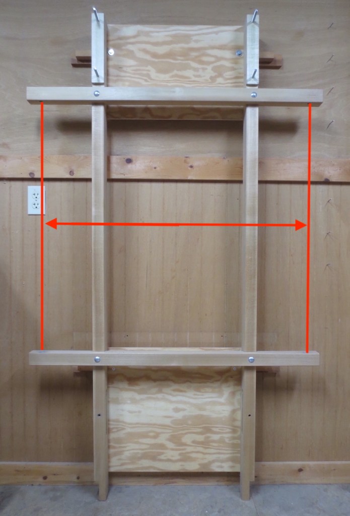
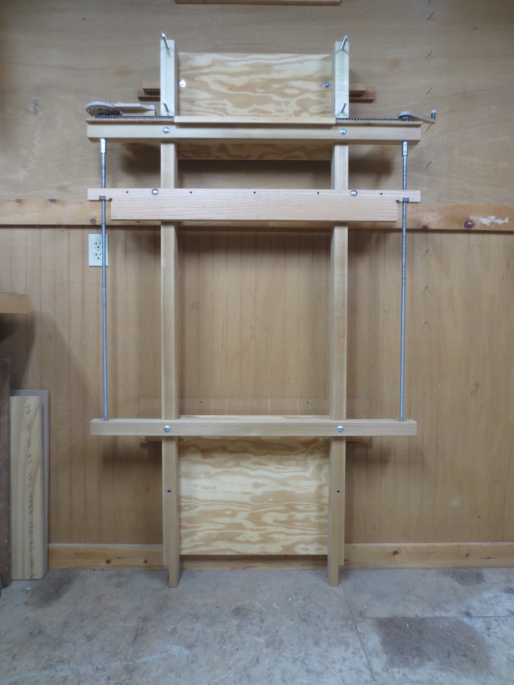
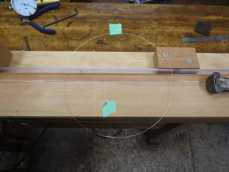
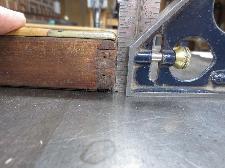
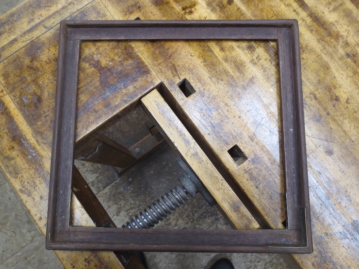
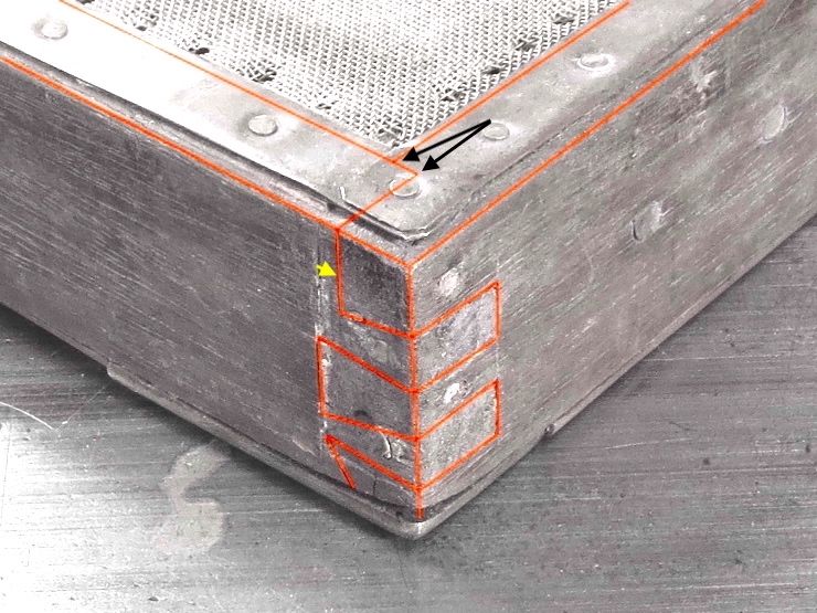
3″ Offset from Front of Loom Uprights
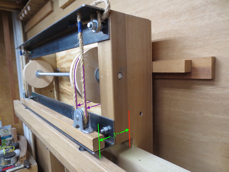
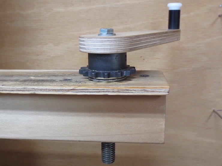
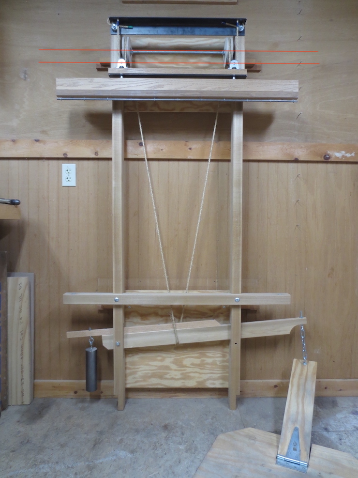
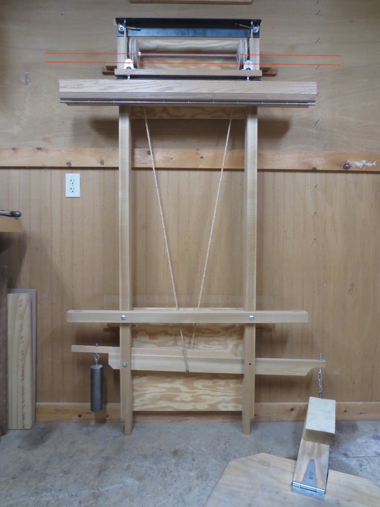
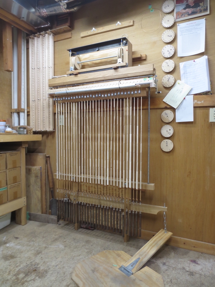
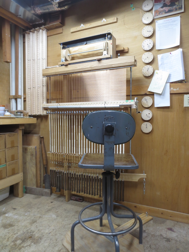
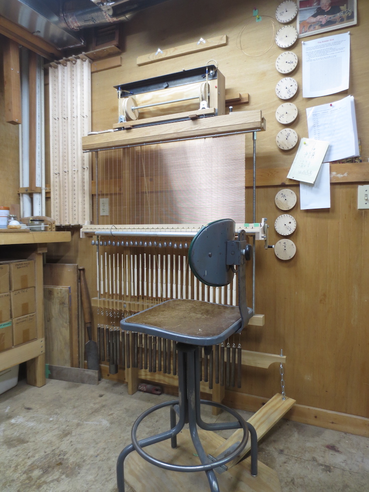
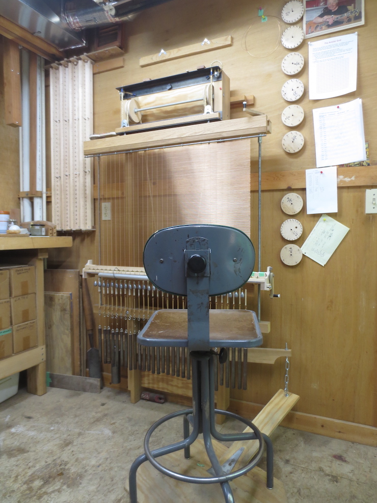
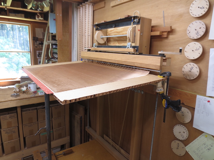
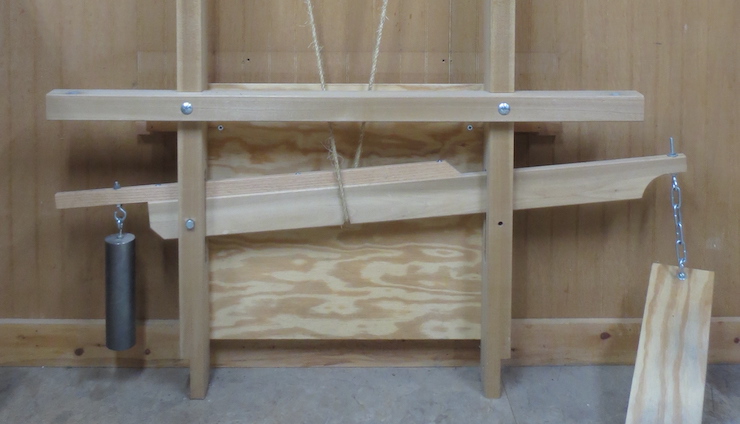
The plywood pulleys are sized and placed so that the rope passing over the back is centered over the treadle lever at the bottom of the loom. More importantly, the rope coming down off the front of the pulleys should be exactly centered over the lifting beam. A wire facing being made on the loom will take the form of a vertical plane hanging directly below the lift beam. This loom is designed for that plane to be located exactly 3″ in front of the faces of the loom frame uprights. The lifting beam and all its moving parts must be centered in this plane as shown above. The red line indicates the front face of one of the uprights. The green line shows the centerline of the upper lifting beam (and other attached parts below). The purple arrows indicate that the rope is also centered in this plane.
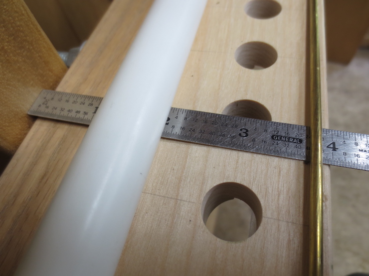
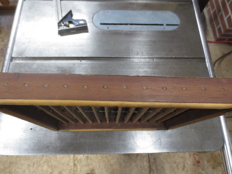
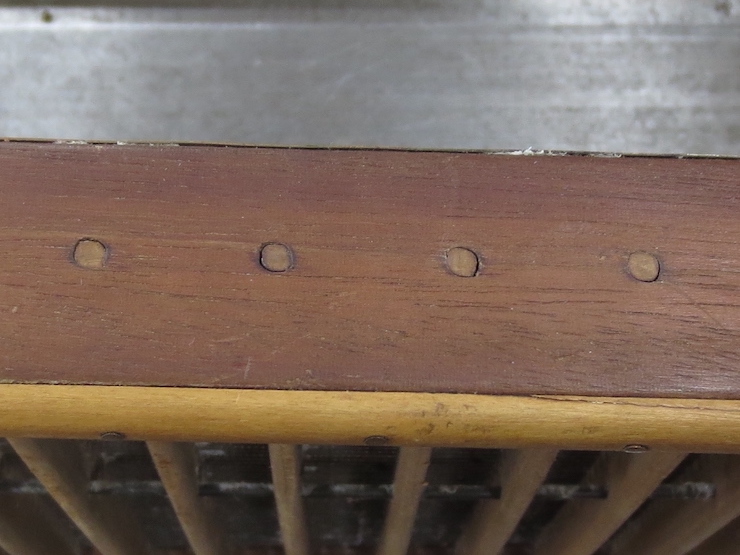
Later when the twisting mechanism is attached the spindles (that fit in these holes) will also be centered 3″ in front of the loom uprights.
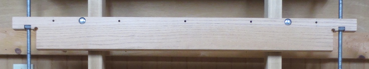
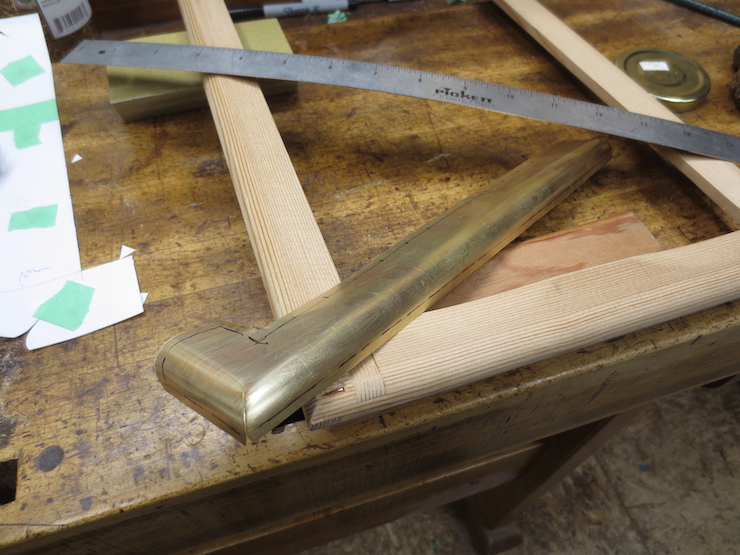
Lifting Beam Assembly
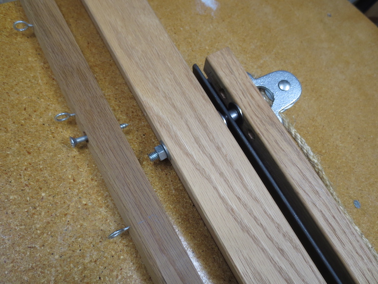
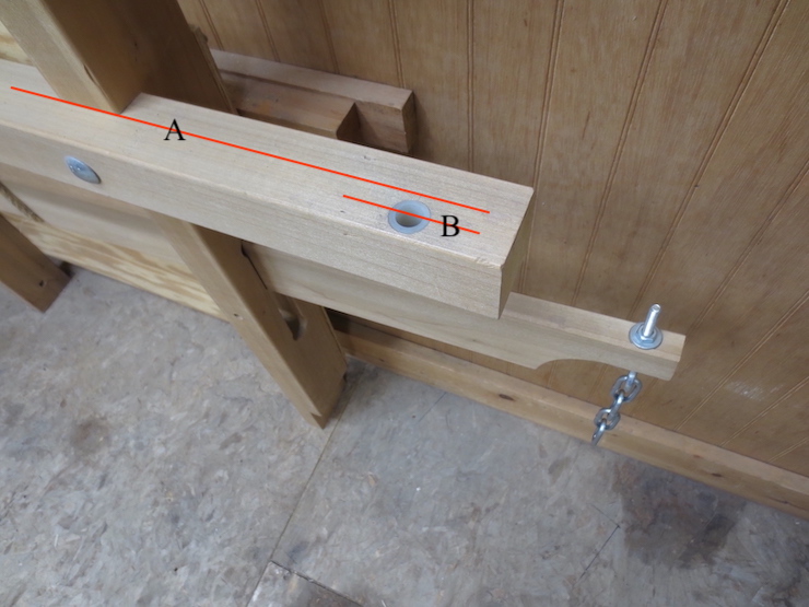
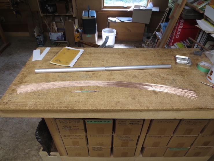
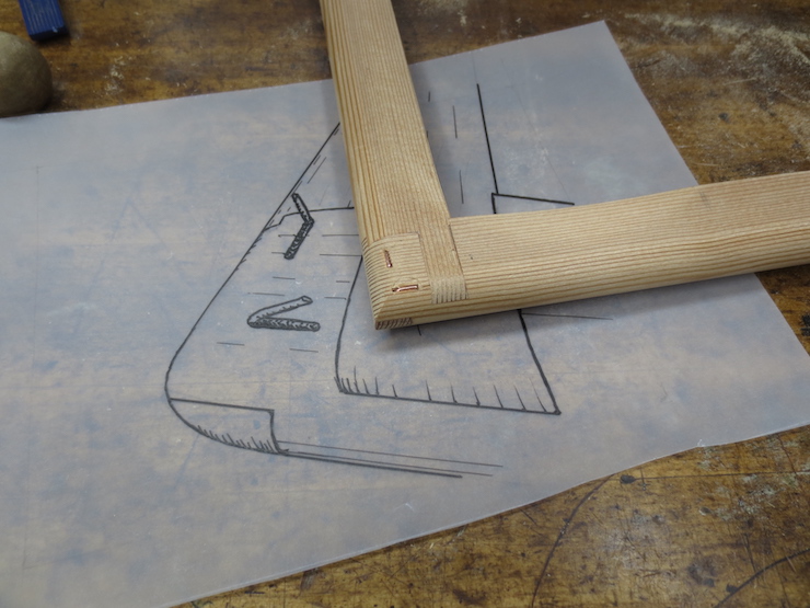
Here the lifting beam is off the loom and partly assembled.
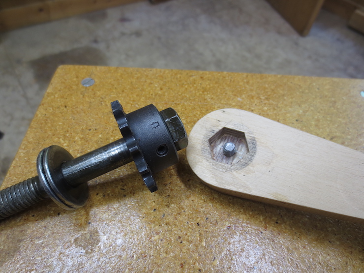
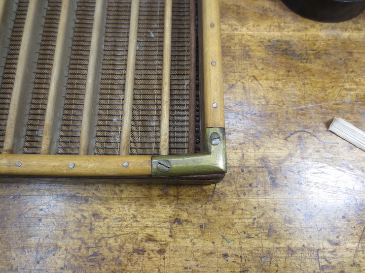
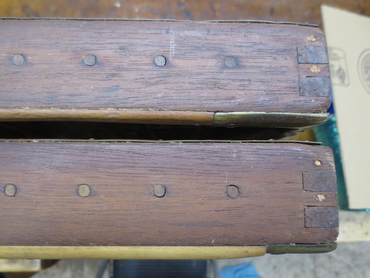
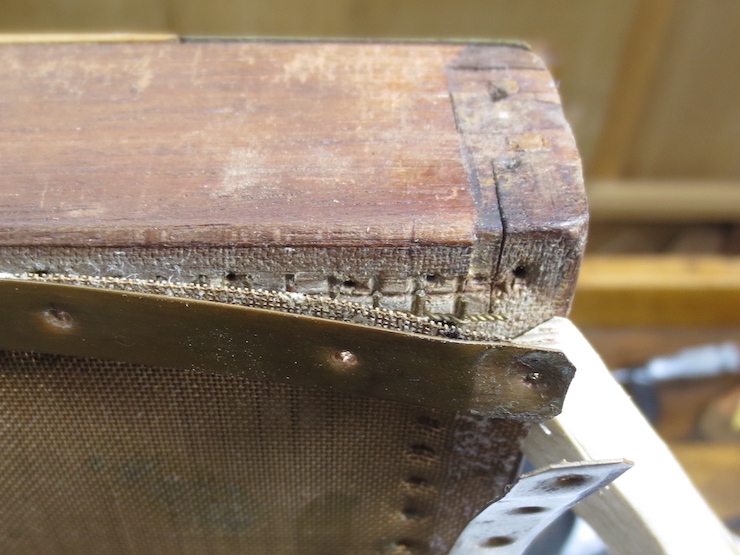
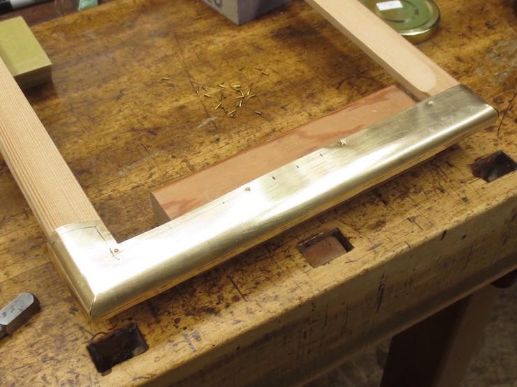
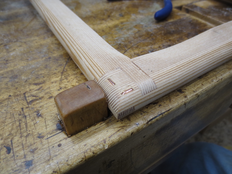
The protruding ends of the bolts fit into holes drilled into the lower part of the beam.

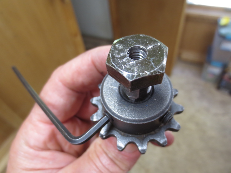
The small steel pulleys are bolted to the upper lift beam with nuts recessed at the bottom.
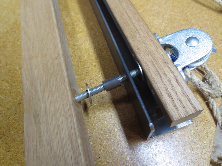
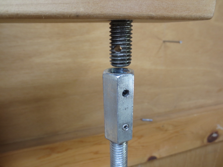
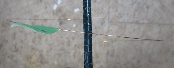
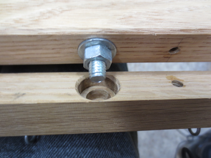
Directly below each steel pulley a steel bushing is flanked by a pair of washers. When the 5/16″ carriage bolt passing through them is tightened (to connect the lower lift beam to the upper one) the three separate steel parts (washers and bushing) are squeezed tightly together to act as a unit. The bushings are 5/8″ long with a 5/16″ bore. The washers are more precise than average washers, all having the same thickness and snug fitting holes.

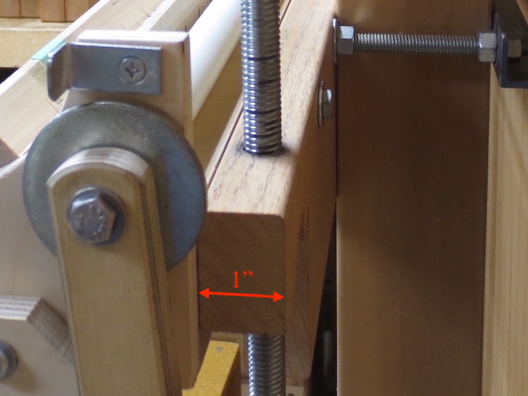
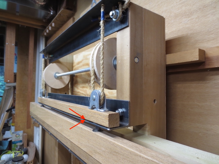
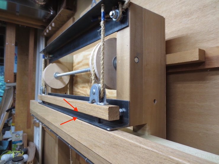
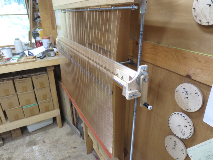
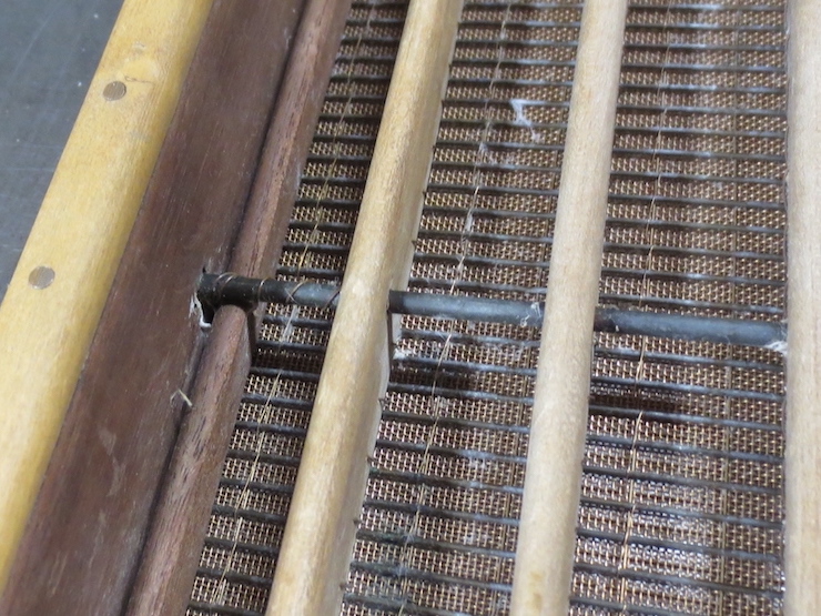
This shows the purpose of the washer and bushing ‘units’ after the lift beam assembly has been installed on the loom. The bushings slide smoothly up and down (through holes drilled in the steel angle) to guide the lift beam. The washers at the top and bottom limit this motion to one half inch. The beam was set to be neither up nor down just for the photo; normally (with the treadle released) the upper washer rests on top of the steel angle. When the treadle lifts the beam the lower washer is pulled up against the underside of the angle.
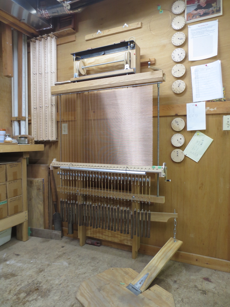
Transferring Motion from Treadle to Lift Beam
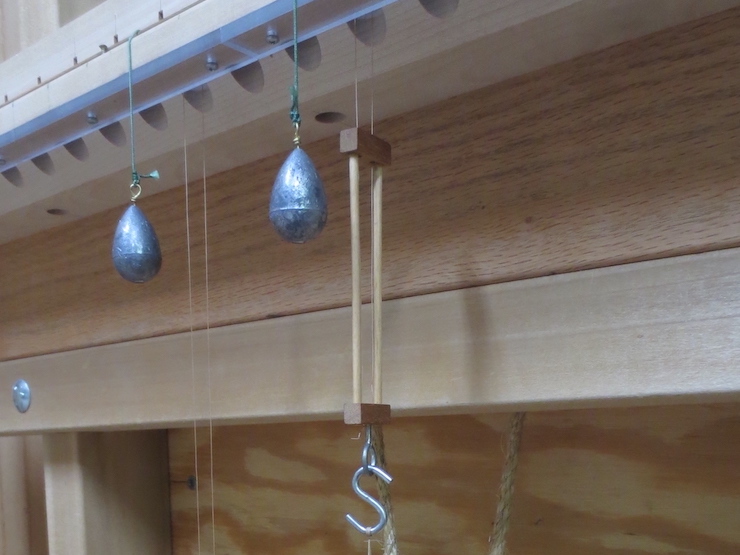
When the treadle is pushed down with the right foot the lever pulls both halves of the rope down the same amount. This is about 1-1/2″ (the rope stretches a bit when pulled tight). The large steel weight serves only to lift the lever and attached treadle when foot pressure is released.
The upper ends of the rope pass over the wooden pulleys from the back. The motion of the rope is reversed by these pulleys to lift the beam assembly at the front. The lower steel pulleys give some mechanical advantage since they only lift the beam 1/2″ for the full inch that the rope travels under them. This makes it easier to raise the facing and attached wire weights which can weigh as much as 45 lbs. if the facing is very large. The ends of the rope are fixed to the top two carriage bolts where they are clamped between washers and extra nuts. These bolts are extra long for this purpose. This is where the rope is adjusted for length to work properly.
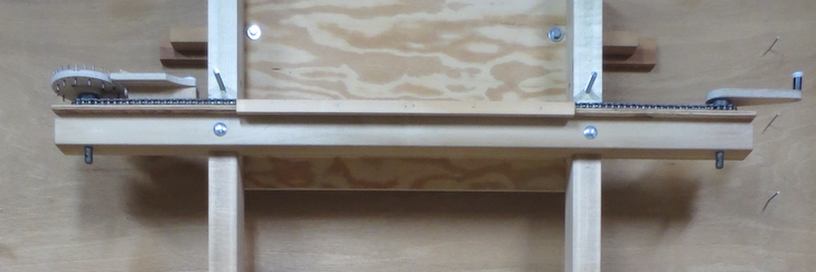
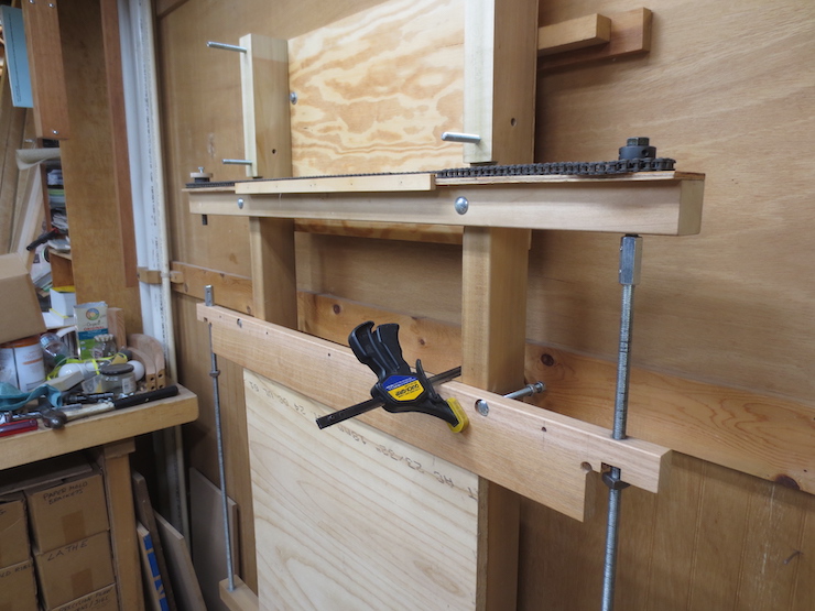
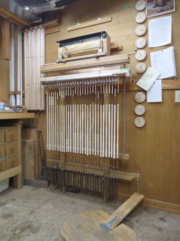
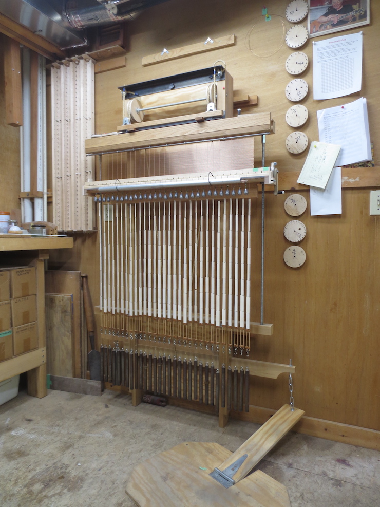
The loom frame equipped with the complete lifting mechanism.