This series of posts should allow for a better understanding of how this loom works. This first post is an overview of the four basic parts of the loom; the frame, the wire lifting mechanism, the indexing mechanism and the chain wire twisting mechanism. Later posts will give more detail on each of these in turn.
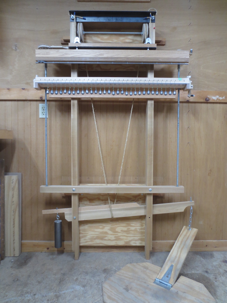
Above, the loom complete, with all its mechanical parts attached. Other essential parts are added when the time comes to make a laid facing or backing. These include wire weights, wire spacers and wire slides.
The Frame
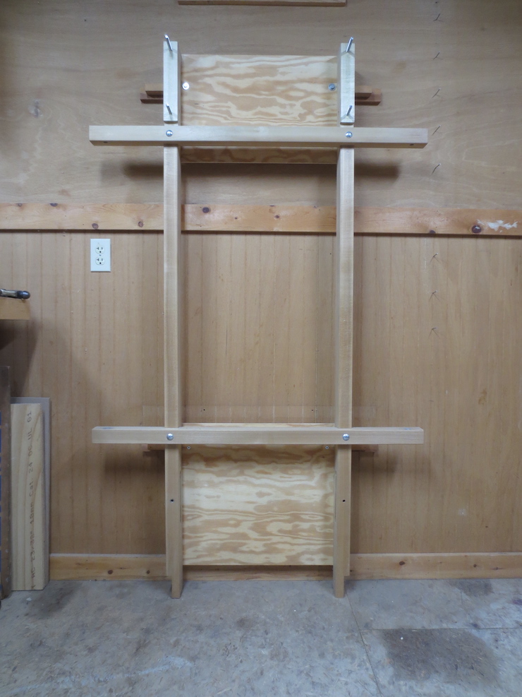
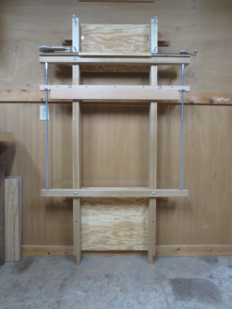
Here is the loom frame stripped of all of the moving parts which are normally attached to it. Two mechanical assemblies will be fastened directly to this frame; the lift mechanism and the laid wire indexing mechanism. The third mechanism, the one that twists the chain wires, is not attached directly to the frame. The loom is fastened to the wall in the photo. This takes up much less space than the free-standing option.
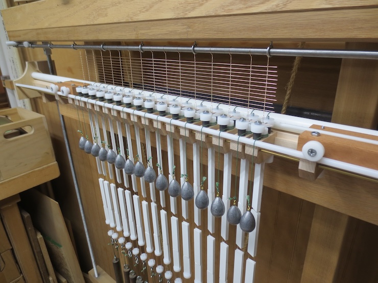
The Lift Mechanism

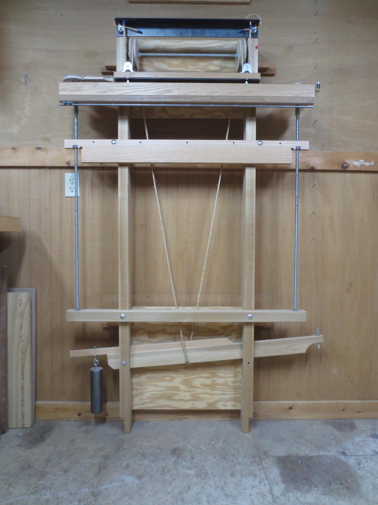
In the photo above only the lift mechanism is installed on the loom. In use it has a simple function; to lift the entire web of wire a short distance (1/2″) to make room for laid wires to be slid in at the bottom, one at a time. When the lifting mechanism is released the wire facing drops back down. The chain wires are then given a half twist to incorporate the new laid wire into the facing. This cycle is repeated hundreds of times to make a facing.
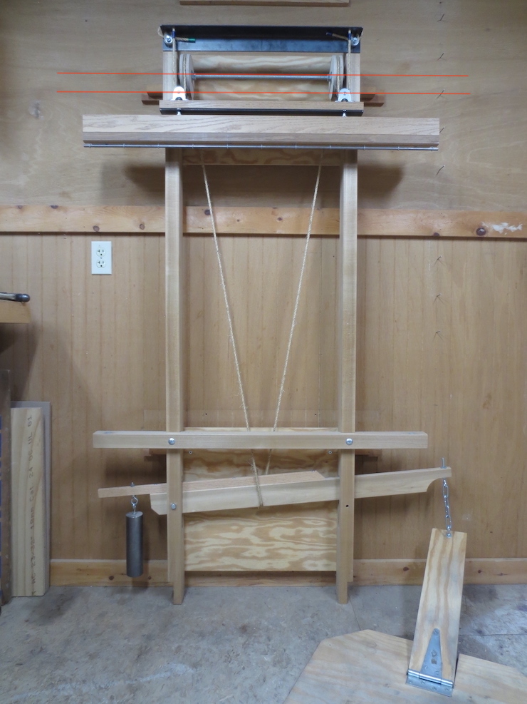
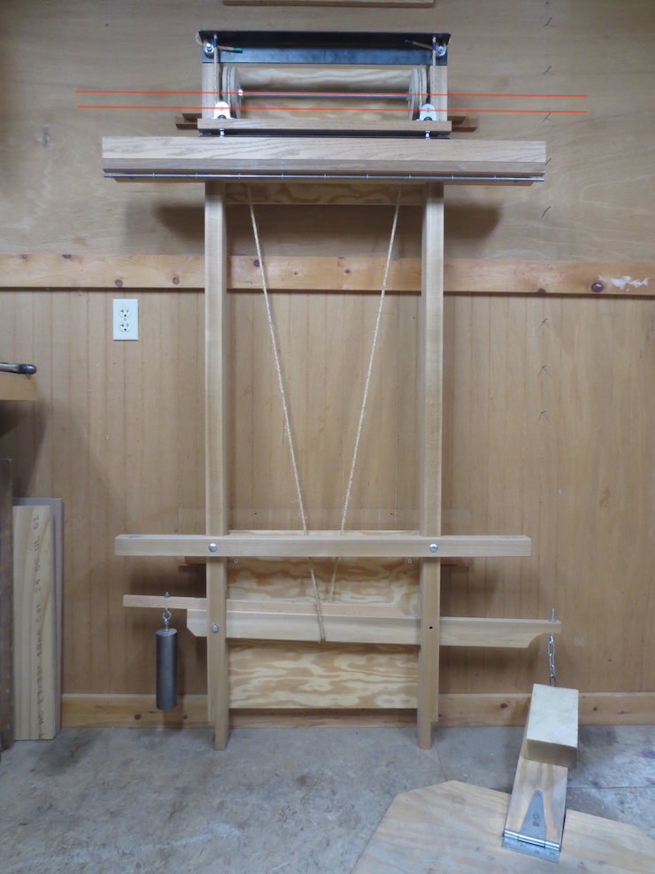
Above are shown the two positions of the lift mechanism, up and down. When the foot treadle is depressed (a brick supplies the force here just to demonstrate) the lifting beam at the top is raised by means of rope and pulleys. The middle of a length of rope passes under a lever which is attached to the treadle on the right. This creates a V shape with two upper ends. Each of these (rope) ends passes up and over the top of a wooden pulley, then down and through a metal pulley and back up to the very top of the loom where it is firmly attached. The inch or so that the rope is pulled down by depressing the treadle lifts the beam and all the wire and weights attached to it a half inch. The lift beam returns to the lower position when the treadle is released.
In both photos above the upper line (red) passes through the (fixed) axle of the wooden pulleys and the lower line passes through the axles of both steel pulleys (movable). Hopefully this makes it easier to see that the metal pulleys (and the beam they are attached to) move up and down when the treadle is depressed and released.
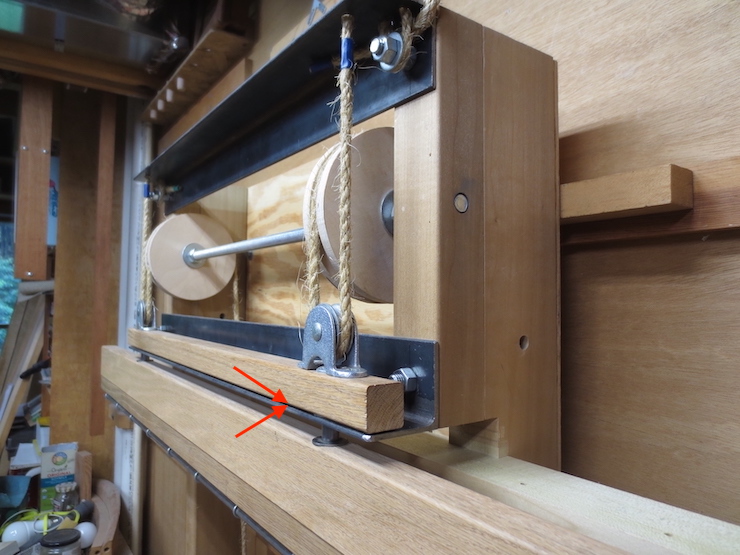
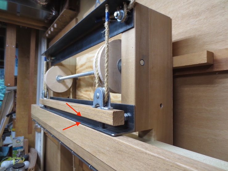
The motion may be easier to see in these two photos. Notice the smaller beam being lifted up from the angle iron which supports it. There’s only 1/2″ of movement and it’s hard to see in the photos so I’ve added arrows to show the gap.
The Indexing Mechanism
In this photo only the laid wire indexing mechanism is installed on the frame. The purpose of this assembly is to lower the chain wire twisting mechanism a precise distance for every laid wire added. The twisting mechanism will be bolted to the top edge of the horizontal ‘traveling beam’ by means of the five holes along the beam’s edge. Identical vertical lead screws are linked with sprockets and roller chain. When the crank at the top right is turned (CCW) the two screws will turn together and lower both ends of the beam the same amount. As laid wires are added the beam gradually ‘travels’ down, ending up near the bottom if a large facing is being made. A counting wheel attached to the top of the left hand lead screw makes it possible to precisely control how far the crank is turned each time. This is done by counting audible clicks as the pins of the counting wheel pass a pawl; the same number of clicks are counted out each time to produce uniformly spaced laid wires. There are many of these wheels, each with a different number of pins, so that a counting wheel can be selected to create a specific spacing.
The Wire Twisting Mechanism
In this photo the loom (with both previously discussed assemblies attached) is ready to receive the twisting mechanism which will be bolted to the traveling beam. The twisting mechanism is self contained and activated by a hand crank at its right hand end. The whole thing moves gradually down the frame of the loom as the wire facing grows larger.

The twisting mechanism is composed of many parts. Above are shown five ‘spindle racks’; a separate one must be made for each different chain wire spacing. Each of these provides the main structure for the mechanism. All of the moving parts are interchangeable and are only installed to complete the spindle rack that is currently in place on the loom. After it is bolted to the traveling beam of the loom and completed the mechanism functions to add twists to the chain wires. The crank twists all chain wires simultaneously. The twisting mechanism is the most complicated part of the loom and will have its own post; probably the last. Please Note: Examine posts #63 and #64 to see the new system of adjustable spindles that replaces and improves on the parts described above.
An image from post #64 showing the new system of adjustable spindles.
The Complete Loom
Once again, the complete loom, with all of the mechanical assemblies attached.
