Designing and building a functional loom requires working out details of how all of the mechanical parts interrelate before starting construction. This post is limited to decisions and dimensions that must be incorporated into the parts of the frame. Many of the dimensions used are somewhat arbitrary but I will emphasize those that directly affect the capabilities of the finished loom.
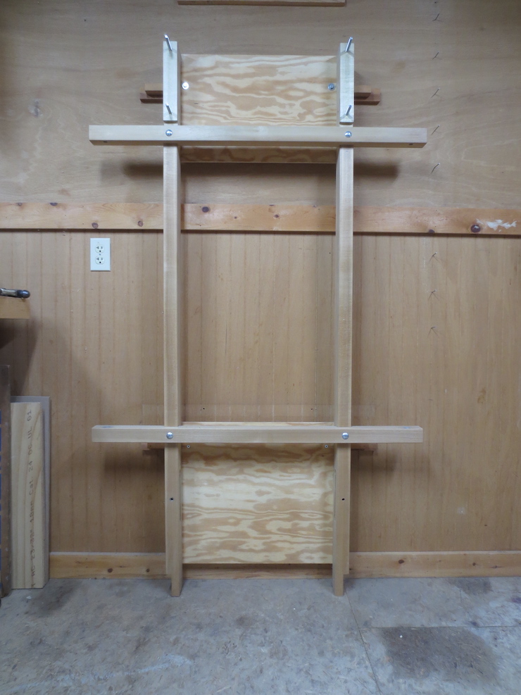
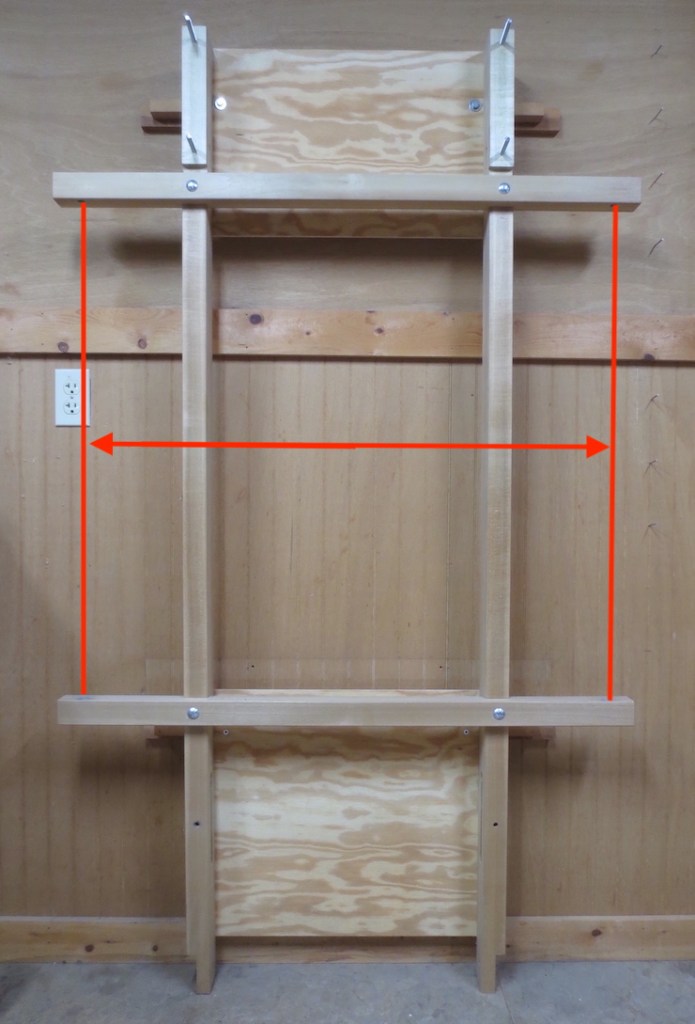
The frame of this loom is fairly simple. The four main parts are made of Tulip Poplar; final dimensions of these were largely determined by the the larger planks they were cut from. Upper and lower cross-pieces, 1-7/8″ x 1-7/8″ x 42″ are bolted to two uprights, 1-3/4″ x 3″ x 71″ tall. These are spaced 22-1/4″ on center. Two 1/4″ thick plywood panels are screwed to the back to brace the structure. The loom is lag bolted and screwed to the wall. As mentioned many of these dimensions are not critical but in order for the loom to work well there are some important things to consider.
Size of the Largest Wire Facing?
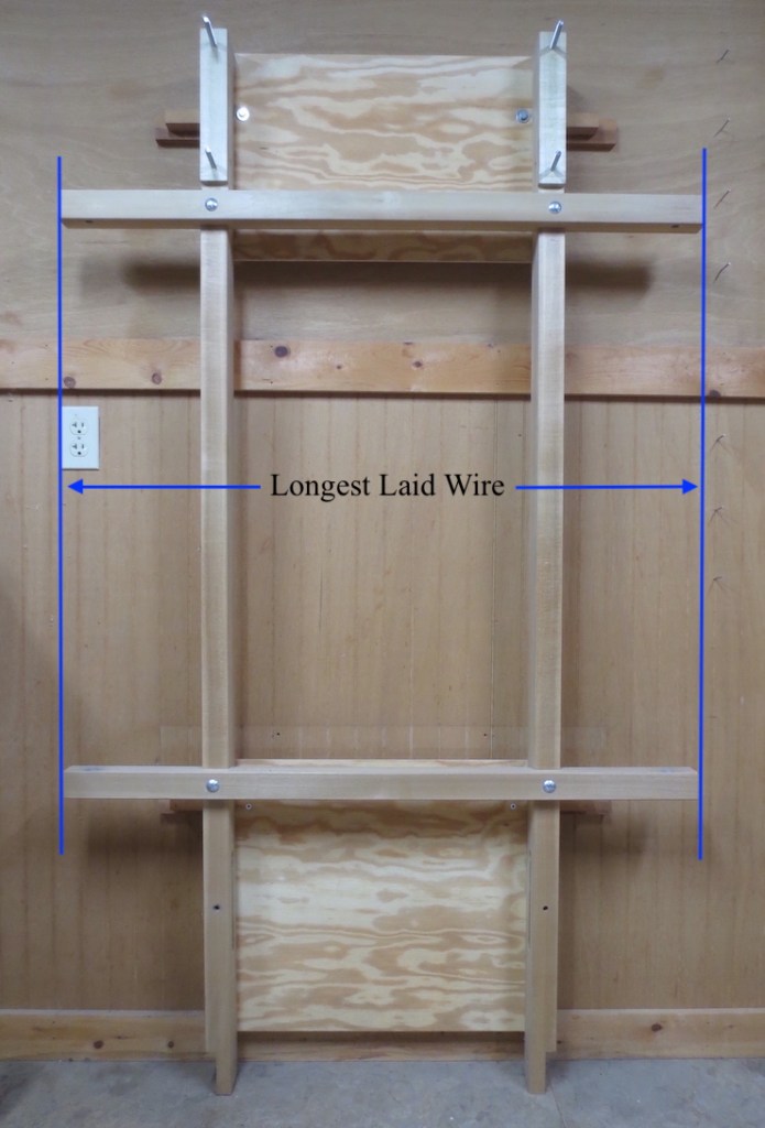
The length of the two horizontal members of this frame, the cross-pieces, determines the longest laid wire that can be used and thus the length of the largest facing. For this loom I chose 42″. These cross-pieces could be made shorter (or longer) depending on the sizes of mould you intend to make.
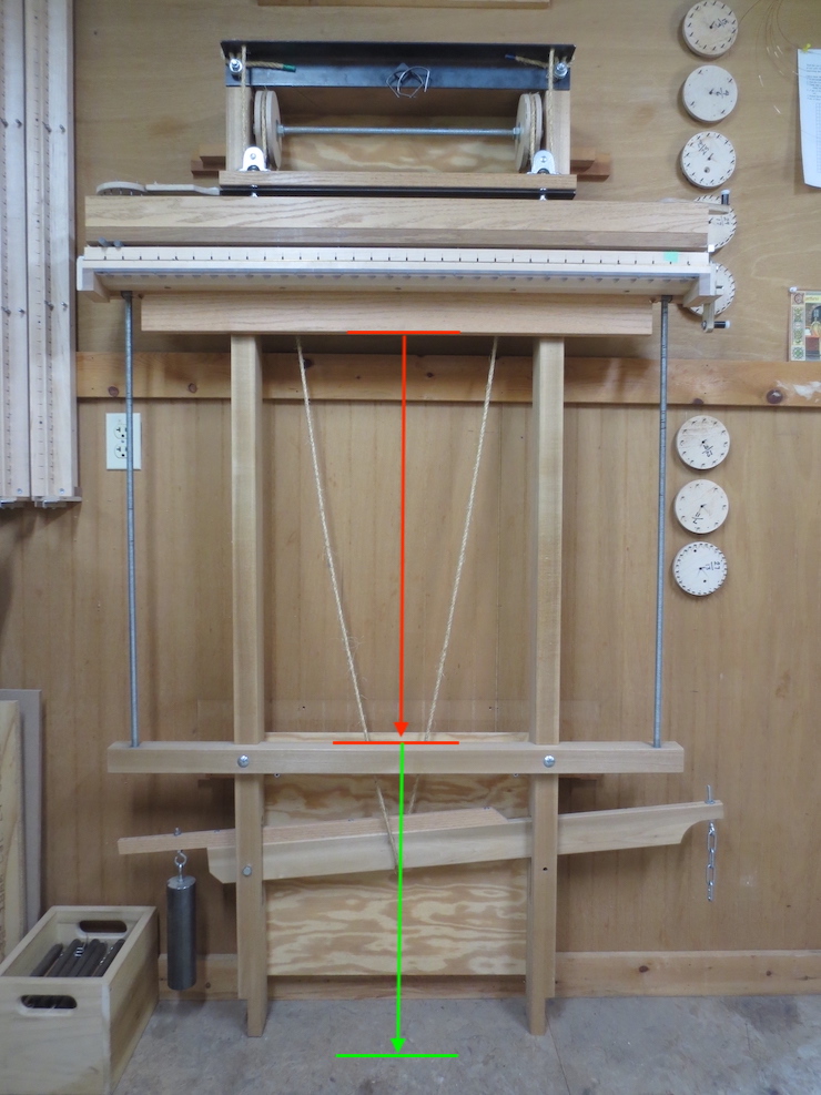
The distance between the upper and lower cross-pieces limits the width of the largest facing. From its starting position (shown here by the upper red line) the bottom of the 4″ wide traveling beam can be lowered 29-3/4″ before it bumps the top of the lower cross-piece. This allows a wire facing width of about 29″ (after accounting for starting and finishing twists). Another important dimension that is built into this loom frame is shown by the green arrow (22-1/2″ long here) indicating an additional space that is sized to provide enough height for the weighted wires should the loom be used to its maximum 29″ width.
Sufficient Wire Length and Enough Space for It to Hang
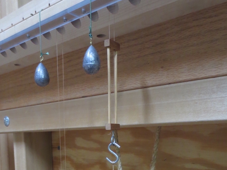
When preparing to make a laid facing lengths of soft wire are hung over the lift rod and attached to weights at the bottom. These chain wires get twisted around the laid wires as these are added, one by one, and as the upper parts of the chain wires get more and more ‘squiggly’ the unused, straight parts below will seem to shrink, pulling the wire slides and attached weights gradually upward. This ‘mock-up’ (pictured in the next few photos) of the largest possible facing tries to show why it is important to take both the wire length and ‘shrinkage’ into account. The mock-up is limited to only two wires, one full length and the other shorter. This second, shorter wire is included just to show how much the first would have moved up had a 29″ facing actually been made here.
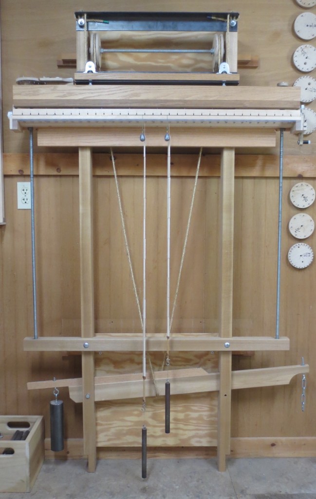
Based on experience I’ve found a standard calculation that works to figure raw chain wire length: width of facing times 2.5 plus 16″. This provides enough length without creating too much waste. The calculation for this (fictional) 29″ wide facing went like this: 29″ x 2.5 = 72.5″. 72.5″ + 16″ = 88.5″. After a piece of wire was cut to this length it was draped over the lift rod. The two ends were passed through the twisting mechanism and twisted together at the bottom of a wooden wire slide. With a weight attached it looks like the one ON THE LEFT above. You can see that the wire can’t be longer since the weight needs to swing free above the floor. This is how this weighted wire would look at the beginning BEFORE the addition of laid wires.
The shorter weighted wire ON THE RIGHT shows how the first one would look AFTER it had been ‘used up’ by twisting in enough laid wires to make a 29″ wide laid facing. The bottom would have risen a little over 7″ from its starting position.

Now the twisting mechanism has been cranked all the way down (as it would have been to finish this fictional super-wide facing). Even though the weight and wire slide have ‘risen’ about 7 inches there is still room beneath the spindles for the remaining wire to swing free as the last twists are added. (The weights, wire and wire slides all need to turn freely as twists are added.) This is important; you don’t ever want the bottom of the twisting mechanism to interfere with the top of the wire slide.
Another view of the waste wire that would be left in the wire slide. This is a good amount.
Locating Holes for the Lead Screw Bushings
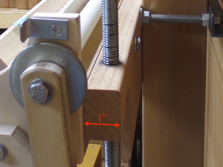
The traveling beam is exactly 1″ thick and the lead screws should pass right up through its center…
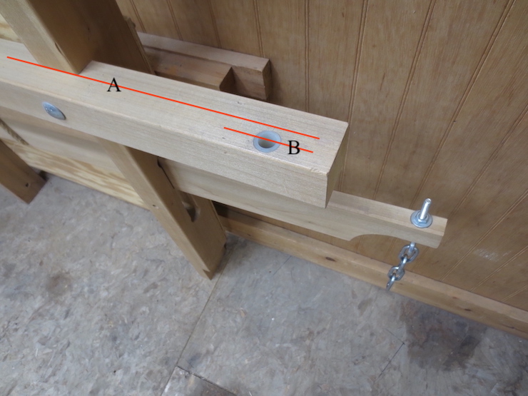
…so the holes for the lead screws should be set exactly 1/2″ in front of the uprights. ‘A’ shows the plane established by the front surfaces of the two uprights. ‘B’ shows the center line of the lead screws (and the traveling beam). The upper part of each hole is drilled large enough to accept standard nylon bushings.
The lateral distance between these holes is figured out in a different way. Upper and lower crosspieces are virtually identical with holes spaced exactly the same.
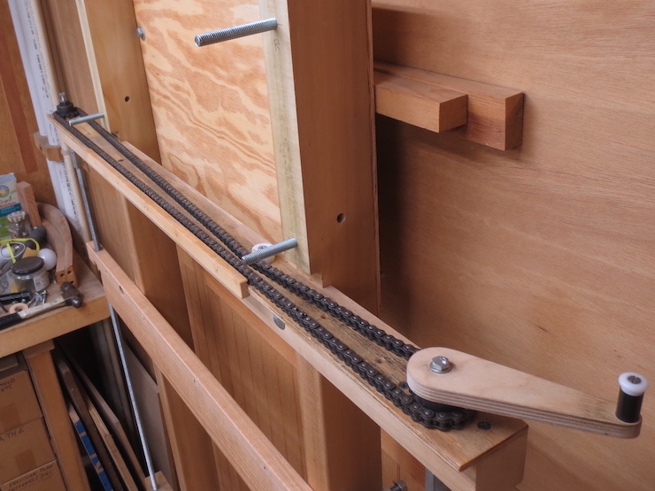
To find this spacing a loop of roller chain is cut to get the twin chain sprockets very close to the preferred spacing. This would put them near the ends of the frame cross-pieces. (Unlike in the photo the linked sprockets and chain would simply be set out on any flat surface in order to do this. I may replace this photo when I have a better one.) The actual center-to-center distance is measured from the sprockets to determine how widely to space the holes drilled down through the cross-pieces. All four holes should be the same distance (left or right) from the center line of the loom. The chain should be a little loose. The two lead screws on this loom ended up just shy of 38-1/4″ on center.
A Place for the Lift Lever
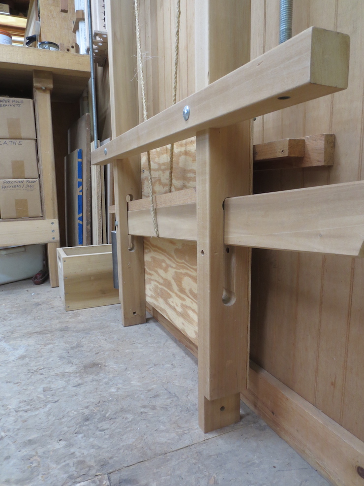
Slots are cut in the frame to accommodate the lift lever. The exact placement isn’t too critical; it needs to be high enough for a weight to be attached to the far end as shown here. The weight serves to return the lever to its starting position when the treadle is released. The bottoms of these uprights are shaped and drilled so that a base can be attached if the loom needs to be free standing. This makes the loom somewhat portable, and able to be set up almost anywhere if needed.
