The next step in making a wove mould is to add a wire that passes back and forth across the top to form a grid. This will support the fine wire screen that will be used as a facing.
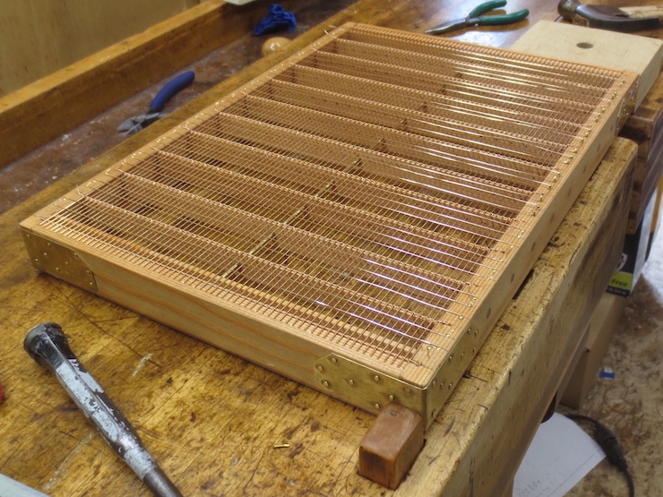
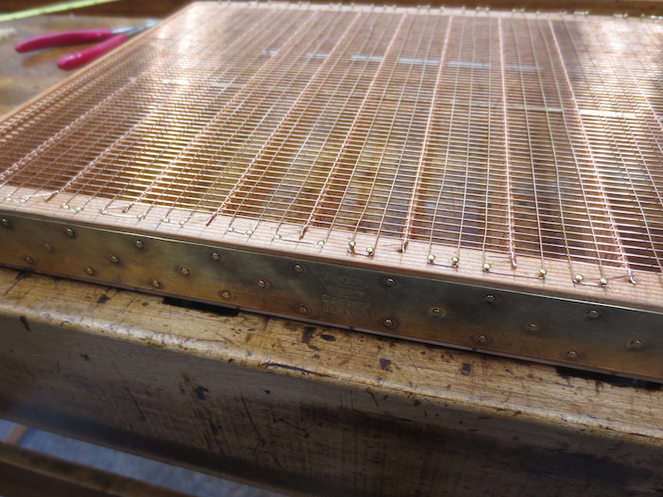
In the photo above the grid is nearly complete; below are the steps needed to create it.
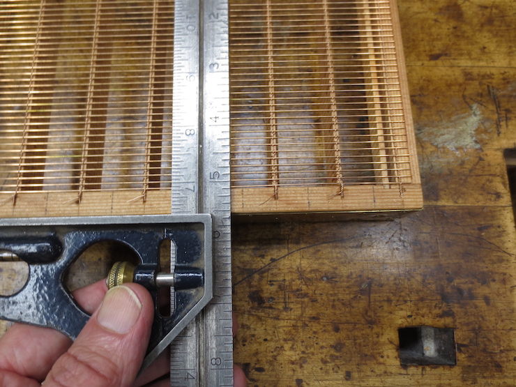
The spaces between the ribs are divided exactly in half and marked with pencil. Then these spaces are also halved.
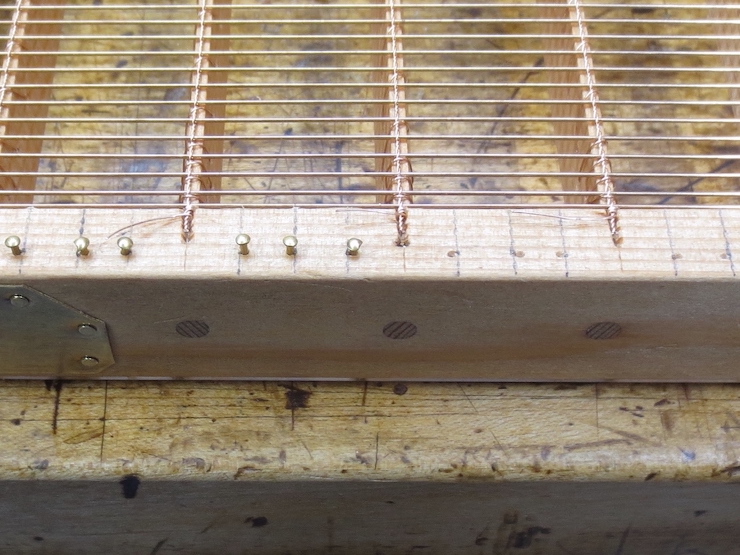
Very small brass nails are hammered part way in for the grid wire to wind around. Notice that the pins are placed to one or the other side of the marks, depending on the course of the wire. This is so the wire will be located right on the marks. These nails are #19 escutcheon pins.

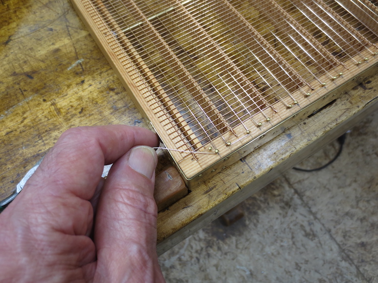
The .015″ diameter wire will be pulled off the spool as it is wound back and forth across the face of the mould.
Winding the wire. The wire was anchored at the far corner by wrapping it around an extra pin which was then driven down flush with the wood.
The other end the wire is anchored the same way.
As the nails are driven home the wire tightens and straightens.
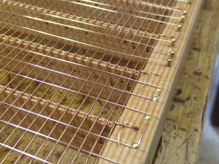
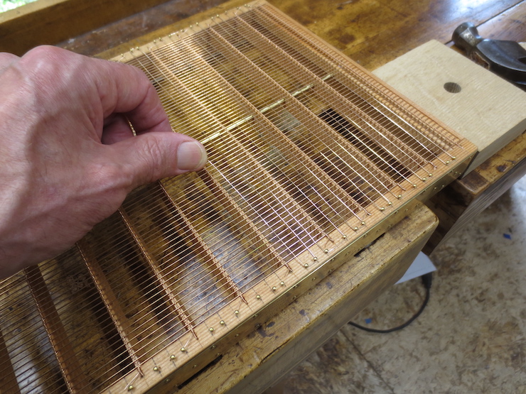
A closer view. This is the first mould in which I have used three equally spaced grid wires between ribs. The two outer ones will be stitched in place as the wove facing is sewn down. The center wire is not sewn in place but is held in place by pressure between the laid wires of the backing and the underside of the wove mesh facing. The pressure pushes it into one of the many grooves formed by the warp and weft of the woven wire facing. The outer two grid wires are also pushed into grooves but are sewn firmly in place. I have seen this pattern on most wove moulds. Previous to this I have made wove moulds with only two grid wires between ribs, both sewn. (Perhaps I didn’t trust the ‘loose’ wire to stay in place.)

Skipping ahead a few steps to show how the grid wires will nest in ‘grooves’ created by the zig-zag warp and weft of the wire mesh facing. A single un-sewn grid wire in the center is held in place simply by being squeezed between the laid wires and the wove facing. It is flanked by two grid wires which have been locked in place as part of the process of sewing the wove facing to the backing/grid structure.

The grid is complete and the mould is ready for its facing.
