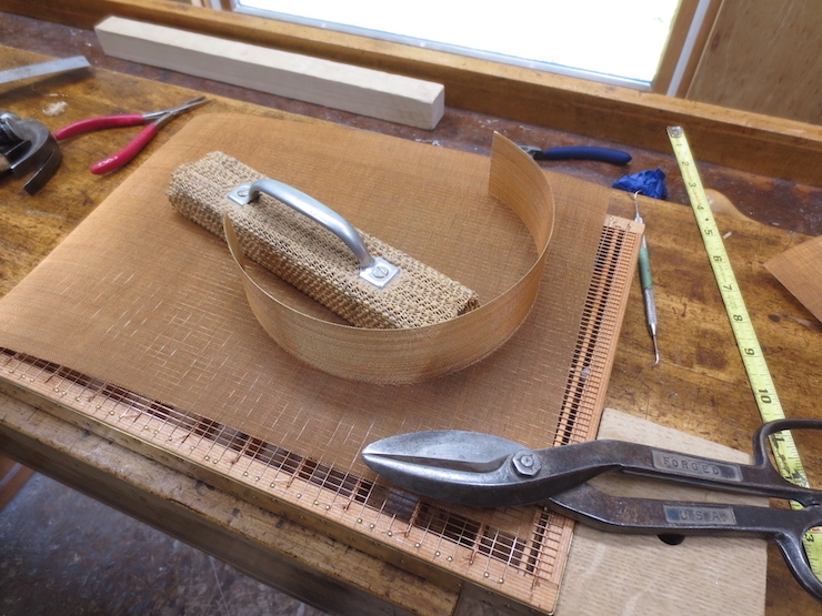
A piece of phosphor bronze ‘wire cloth’ is cut to the size needed. I have always used phosphor bronze for this though it is more difficult to find than ‘plain’ bronze or brass. Either of these would likely work well but are less durable. Paper mould wove facings typically are made from wire cloth in the range of 40 to 50 wires per inch, though I have seen finer. The wire cloth I have used was purchased from a Dandy Roll manufacturer. This wire seems to use a slightly heavier wire for a given mesh size than some brass and bronze wire cloth I have found.

Care is taken to align the weave of the wire mesh with the grid wires since they must follow the ‘grooves’ in the wire facing. A few brass escutcheon pins hold the wove facing in place.
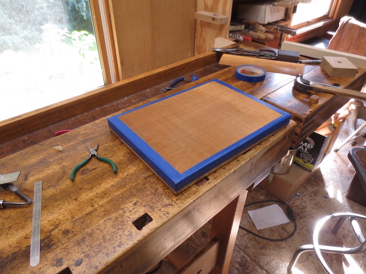
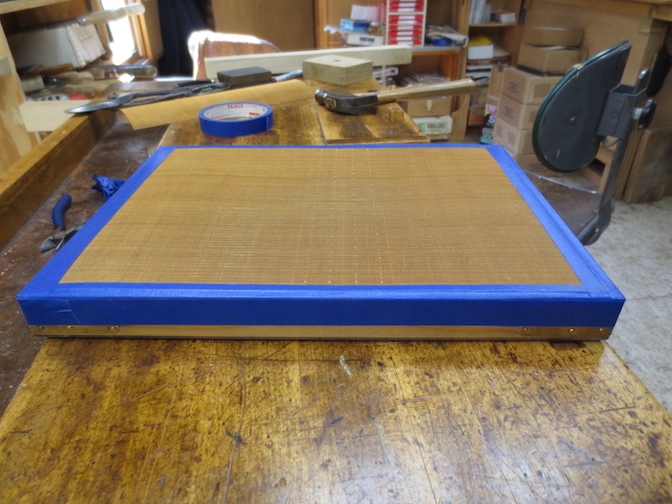
The tape protects the edges of the wire so it won’t get damaged while the mould is being sewn.
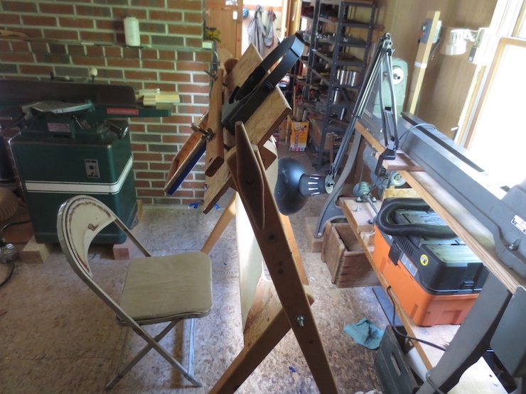
The sewing frame is adjusted to hold the mould a bit higher so that the row being stitched is near eye level. A piece of paper hangs from the cross bar and is backlit. The room can be dim. It is easiest to sew by seeing the wire in silhouette.

Another view. I wear a #4 optivisor while sewing the wove facing.

This is what the completed stitching looks like. The sewing wire crosses under* three laid wires (of the backing) between stitches taken over* two wires of the facing. The stitches are staggered, offset by one laid wire with each new row. This creates a diagonal pattern to the stitches. At the ends (not visible here) the stitches are identical for all rows (not staggered) and a ‘knot’ is formed, securing the sewing wire and tying the facing securely to the last ‘free’ laid wire of the backing. (This ‘free’ wire is actually the second wire, the first lies right next to the wooden frame.)
You can see that the two outer grid wires are sewn while the middle one ‘floats’, though it is held quite firmly in place between two layers of wires. I sew wove moulds with a .008″ diameter soft phosphor bronze wire. Each row is started from the middle of the mould, sewing from middle to right with one end of the wire and then middle to left using the other end. This makes it easier (less wire to handle) and keeps the wire fresher. Each sewing wire takes the form of a long spiral as it travels the length of one grid wire, passing under three laid wires, then coming up over the top and crossing two wires of the wire cloth, then passing once again under the next three laid wires, etc.
*Under” and “over” here refer to the mould in the upright position, not upside down as in this photo.
Four rows of stitches have been completed. You can see them just to the right of center.

To the left of this row of stitches you can just see a rib below the mesh. To the right you can discern the middle (un-sewn) grid wire nesting in a groove created by the wires of the mesh facing.

To keep the stitches as inconspicuous as possible they are sewn in a certain way. As a sewing wire crosses two wires of the mesh on top of the mould it crosses the first wire at its low spot. Then it takes a slight diagonal to cross the second wire at its low spot. As the row is stitched the openings that the wire passes through are chosen so that the sewing wire’s diagonal path crosses over the top in the same direction as the general path of the wire. If the wire is forced ‘backwards’ by passing through the wrong two openings it will protrude a little more and make a bigger ‘bump’ on the top of the mould.
This process is not as difficult as it sounds. When the mesh is viewed at an angle the square openings change to look like rows of alternating trapezoids, some pointing down, some pointing up. Once you figure it out you can use this trick to easily put the stitches in the right spaces.
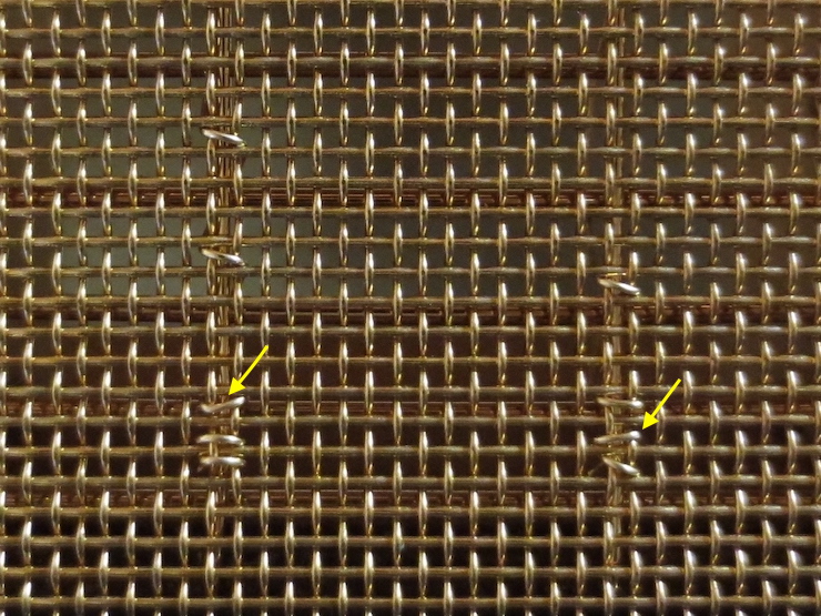
You can’t choose the openings when making the last three stitches to form the ‘knot’ so this process can’t be followed here. Visible in the photo are two stitches that were forced to cross ‘backwards’ by the low spots in the mesh, reversing their angle. These stitches (indicated by yellow arrows) ‘break the rules’ and as a result don’t lie quite as flat. It doesn’t matter in this case because this part will lie under the deckle and paper won’t be formed here.
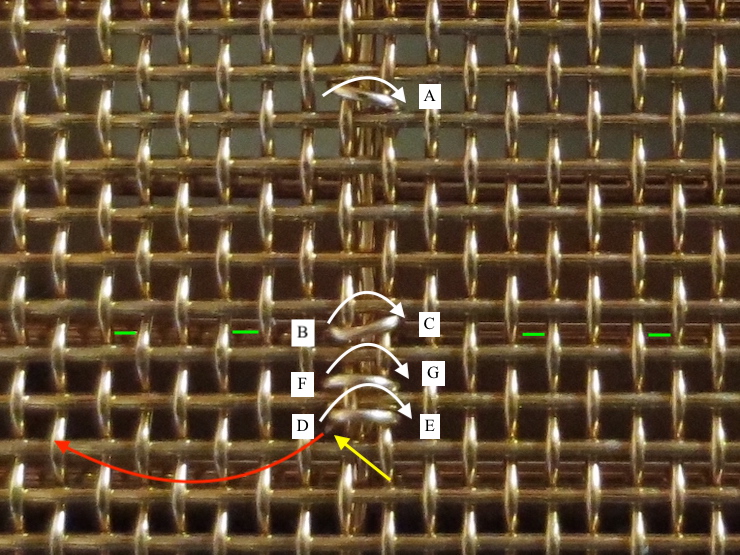
A view of of the ‘knot’ from above. To form the knot the sewing wire passes down through the ‘hole’ at [A] and comes up at [B]. It then crosses over two wires on top and down through [C] before passing back under to come up again at [D], crossing under the laid wire in the process. The sewing wire goes down at [E] and ‘reverses course’ to pass up at [F]. This time the wire is left a little loose. After the wire is pulled down through the mesh at [G] the end is poked under the previous stitch (between [E] and [F], not visible here) before passing up through [D] once more. The end of the sewing wire is then pulled which tightens the stitch that was left loose. This has the effect of trapping the wire near its end. The excess wire (represented by the curved red arrow) is pulled and rotated until it breaks off just below the surface (at the tip of the yellow arrow). The wire always breaks in the same place just below the surface due to the rotating action. This weakens the wire in this spot before it is pulled hard enough to break. Note that the stitches of the knot are directly adjacent (on both sides) to the last ‘free’ laid wire which is indicated here with green dashes. The knot ‘lashes’ the mesh facing down to the laid wire as well as securing the end of the sewing wire.

A view from below showing the sequence used to form the knot. The last stitch before the knot [A-B] is always located in the third space (located between the third and fourth laid wires) from the wooden frame.
Starting at [1] the sewing wire enters the opening right next to where the laid wire and the grid wire intersect. It passes over two mesh wires in the usual way and comes back down* through [2]. It then passes under* the laid wire and skips over a mesh to pass through the opening at [3]. After crossing the same two mesh wires on top it comes down through space [4] and ‘reverses course’ to pass through space [5], right next to the laid wire. For now this new stitch is left loose. This is so that after the wire is fed down through space [6] it can be poked through the loose stitch before passing one more time up through space [3]. You can see that the very end of the sewing wire is now held in place by the previous stitch. The knot has been completed; now the sewing wire is pulled tight and the end is rotated and pulled until the wire breaks. The red arrow points at the broken end of the wire.
*Once again keep in mind that in this photo the mould is upside down and that “over”, “under”, “up” and “down” may seem reversed.

In this photo the green arrows show the location of ‘knots’, where ends of the sewing wire are secured, straddling the last free laid wire, which can be seen beneath the wire mesh if you look closely. The yellow arrows show the row of stitches that fall in the space between the same two laid wires of the backing. The black arrows show the locations of ‘regular’ stitches, the stitches that secure the rest of the wove facing to the laid backing/grid wires. These are placed in a diagonal pattern visible here.
I hope this gives a fairly complete description of this process. I may have left out some details which would have helped explain things more clearly. Let me know if this is the case in this or any other post; I may be able to ‘fill in the gaps’ with more photos or text.
