The next three posts will show how the other half of the deckle joint is made. This half of the joint takes longer so the process is broken into segments.
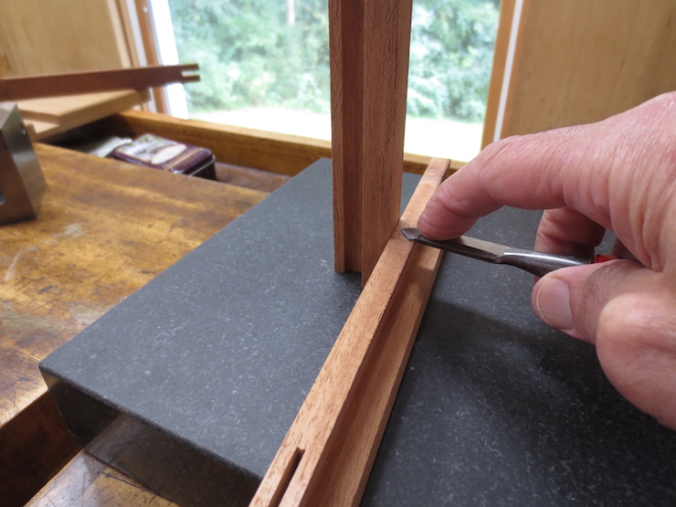
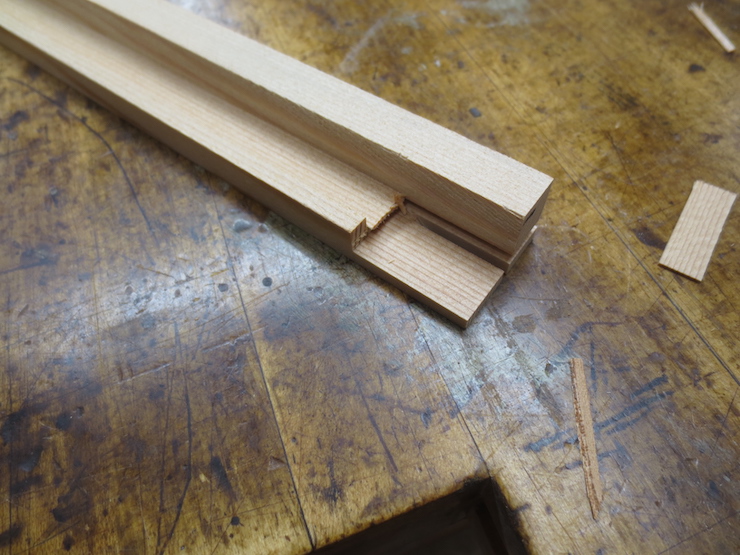
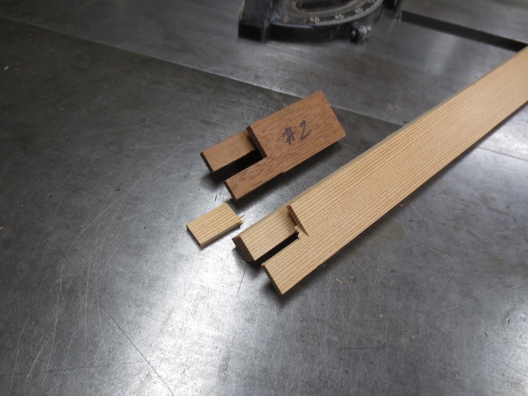
One side of a saw cut establishes the bottom surface of the sliding dovetail; making it the right thickness to slide into the dovetail groove. The same saw cut starts a slot to fit a tongue that has already been made. Since both tongue and slot are the full width of the deckle, a deckle part can be used as a gauge when scribing the part (above) to prevent ‘chip out’ when the saw exits the cut.
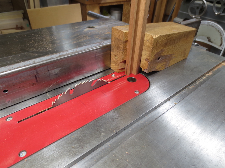
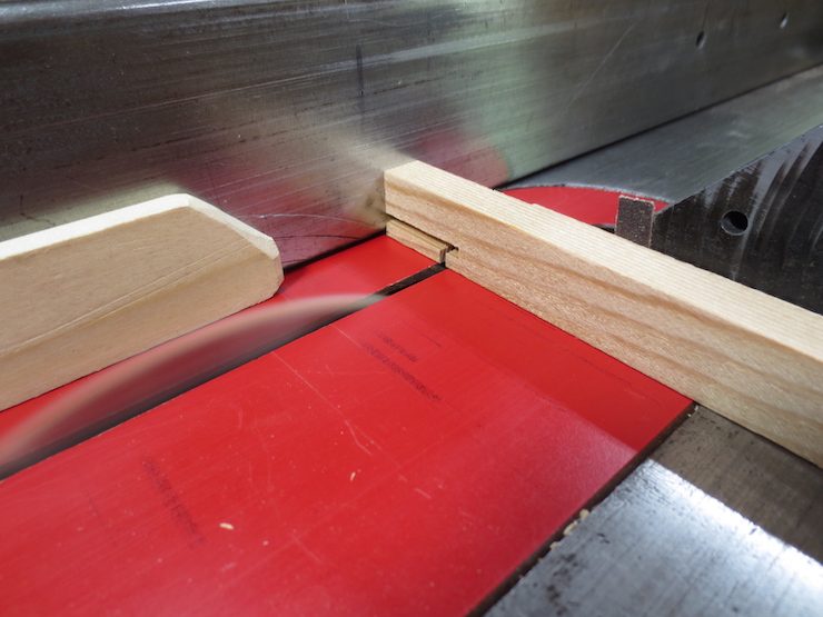
Here is how this slot is cut using the right angle block.
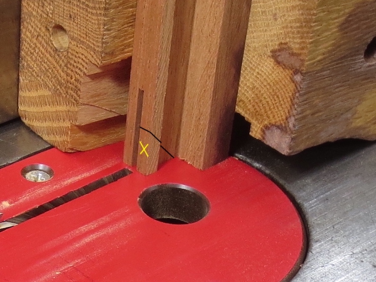
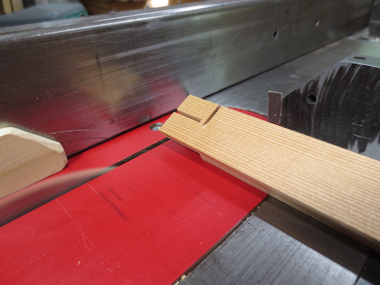
Some waste can be sawn or chiseled away after removing the test part from the saw. The black line shows the imaginary saw cut and the waste is marked by the yellow “X”. Removing this bit of waste (only on the test piece) makes it possible to test the end of the dovetail tenon against the slot it must fit into. (See photos at bottom of post).

The thickness of the sliding dovetail (indicated by the black arrow) can now be tested and trimmed to fit the groove. The first cut leaves it slightly thick on purpose. In one or more tries, the table saw fence is reset (with the help of the dial indicator fixture) to improve the fit of the scrap test part. When the fit is good all of the deckle parts are cut the same, finishing this step. Next the slot must be widened (by moving the fence and making another saw cut or two) to fit the ‘tongue’ that was previously shaped on the other end of all the deckle pieces. The green line shows how the slot will be widened.
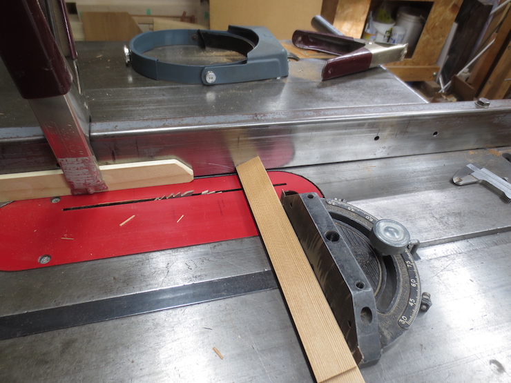
Next a small cut is made across the rim of the deckle. In the photo below the right end of the red arrow points to it.
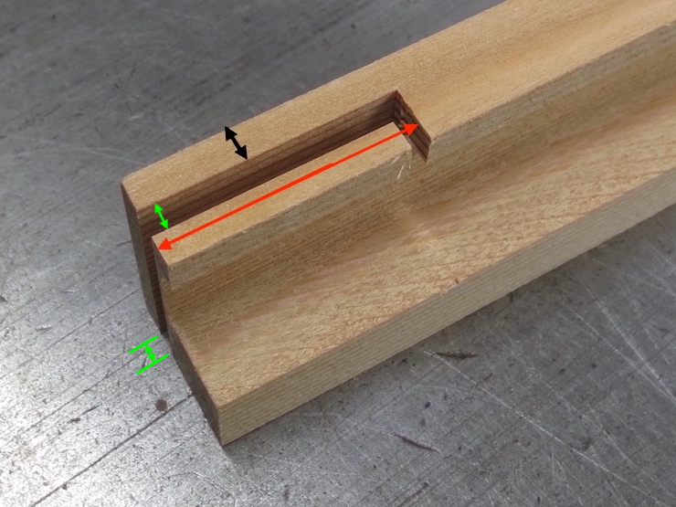
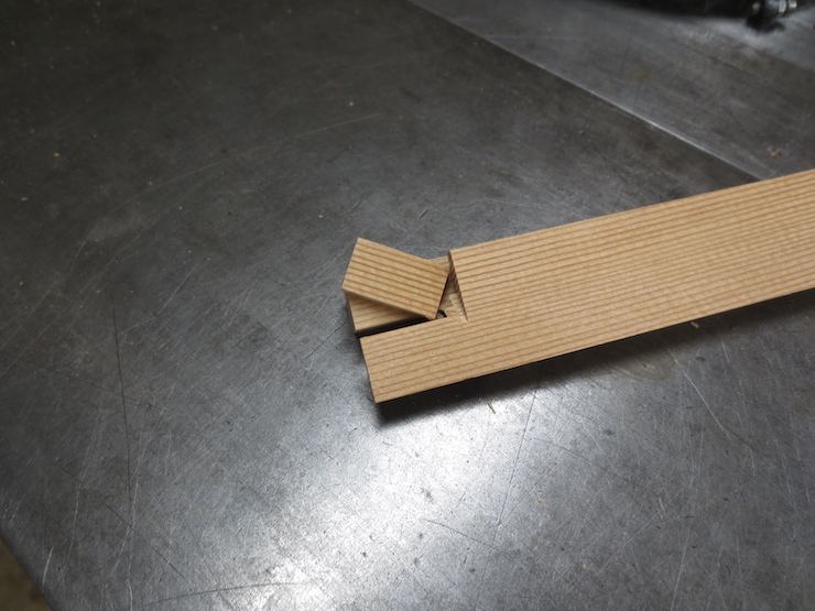
The partly finished joint now looks like this. The dimension indicated by the black arrow is now exactly the same as the depth of the dovetail groove that was cut in the first half of the joint. The dimension indicated by the red arrow is the same as the width of the deckle parts. The slot shown by the green arrows has been widened to fit the previously shaped tongue on the opposite joint. Each of these finished surfaces have been tested against the appropriate parts of the other side of the joint. (The photos at the end of this post show how this is done).
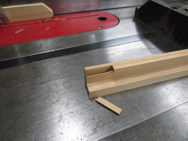
The next few steps rough out areas that need to be ‘cleared out’ to allow the dovetail tenon and lap tenon to be fitted more easily (in the next post). The first piece of waste can simply be broken off (above).
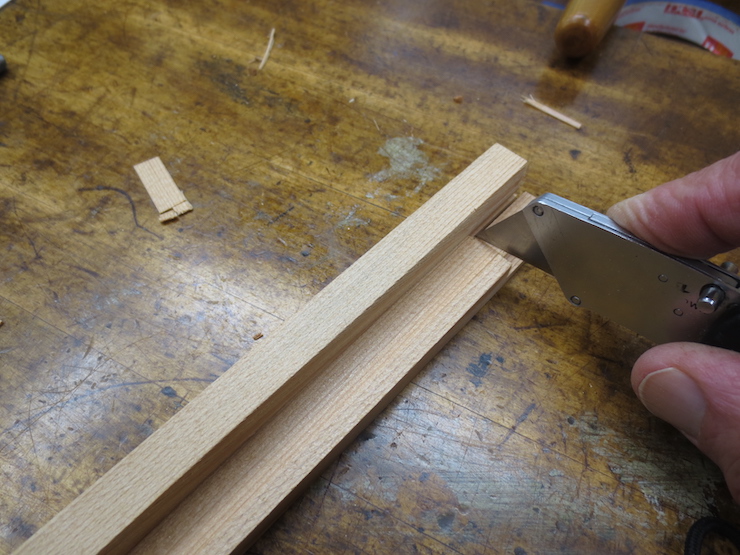
The next part can be cut off by hand with a utility knife. The shoulder near the tip of the knife will be trimmed to exact size later.
This cut is not exact either, but the first step in removing another waste area.
The same cut shown from below.
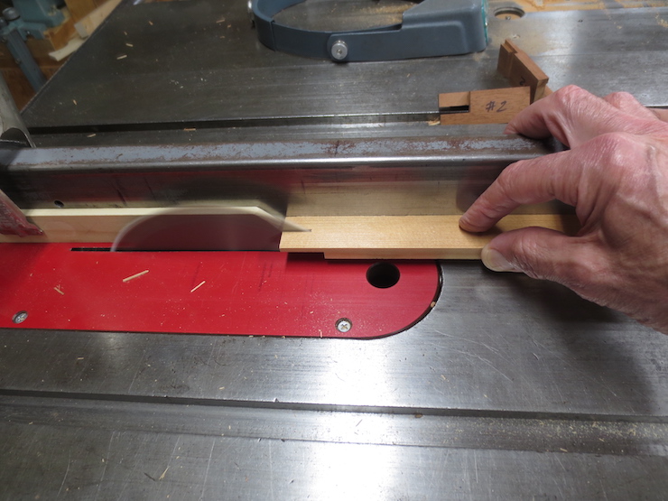
Another roughing cut is made. The height of the blade is set to cut across the waste without touching the ‘good’ part.
The two roughing cuts seen from above.
Now this part can be broken away on all of the pieces.
Removing the waste frees up the two tenons so they can be trimmed to fit into their corresponding groove and slot (covered in the following post). The sliding dovetail tenon (on top) is now the right thickness but needs to be trimmed on both sides. Parts of the lower tenon will be cut away to form a ‘tongue’ to fit into the slot prepared for it (see the previous post). Shaping this tongue creates a notch that will receive a lapping part, also shown in the previous post.
A completed example of the joint is shown for comparison above.
Testing the fit
As parts of the joint are shaped they are tested against the (previously finished) first half of the joint. The examples shown below have joints that have been completely shaped but serve to demonstrate the method.
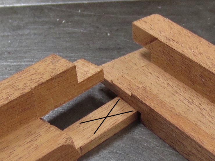
The thickness of the sliding dovetail tenon is tested against the groove it must fit. If the parts are held firmly against a flat surface the mating surfaces should be able to slide past each other with little resistance. The surface that is being adjusted is indicated by the black “X”.
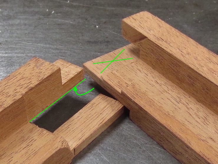
Likewise the other side of the slot can be tested against its mating surface. The green arrow points at the (hidden) surface that is being trimmed to fit against the surface indicated by the green “X”.
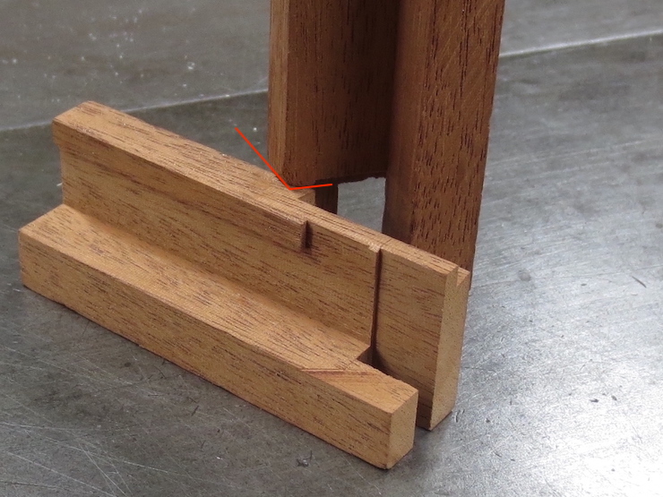
The cut across the rim of the deckle can be tested by standing the test piece on end. The red lines indicate the surface that is being trimmed to fit.
