Cut parts to length, scribe and mark joints
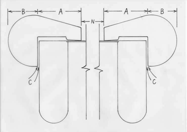
To make the mould and deckle fit together properly you need to know the deckle overlap (A), the width of the deckle (A+B) and the amount of space to leave between mould and deckle (C). More detail on this will follow later in this post.

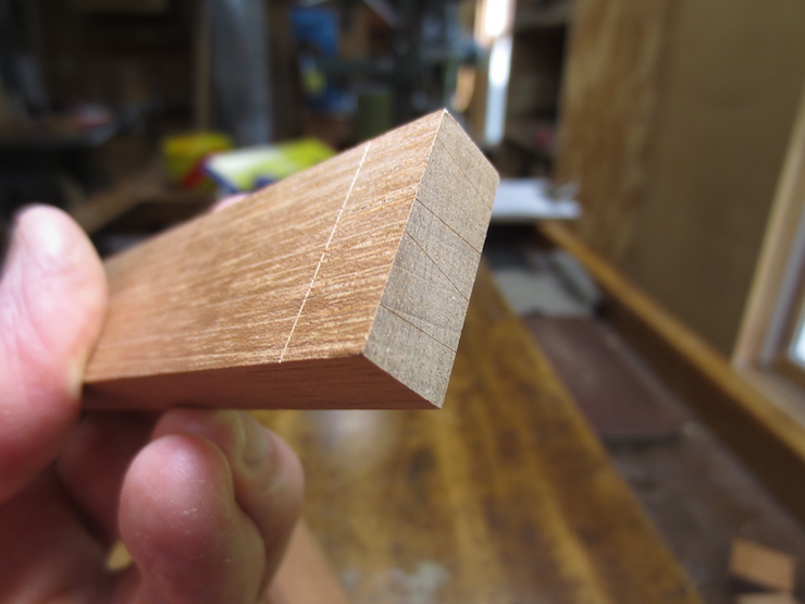
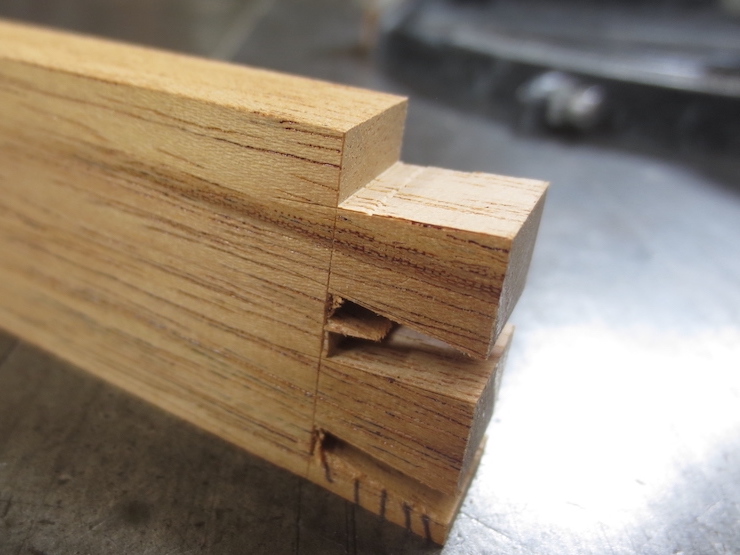
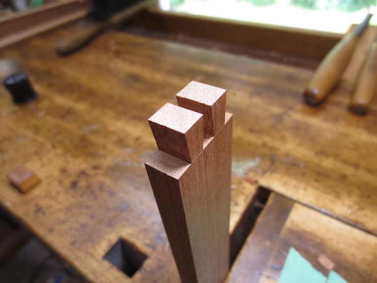
The mould frame is joined at its corners with dovetail joints. The two protruding parts on the left are called ‘tails’ and the three parts on the right are called ‘pins’. Remembering this will make it much easier to understand this post.
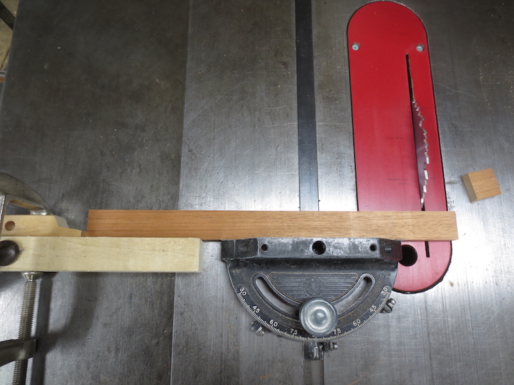
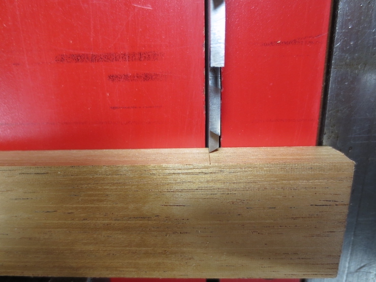
Using the hollow ground planer blade the mould frame pieces are cut to exact length with ends that are square.
Using one piece of a mould frame to scribe a line on another. All pieces are scribed this way to begin marking the dovetail joints. Those with tails (the short sides of the mould) are scribed on all four sides and those with pins (the long sides of a mould) are scribed on two sides.
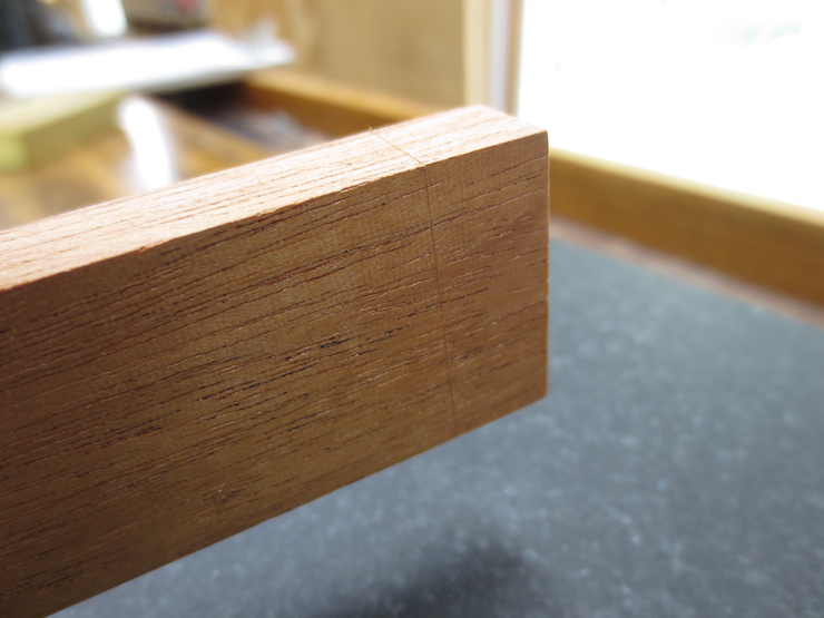
The scribed line defines the bottoms of the joints.
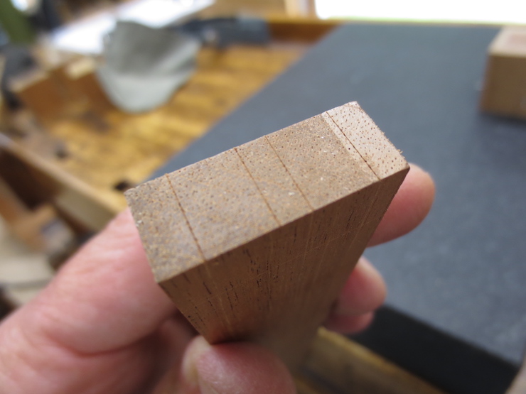
I use a small block of wood with four sharp steel pins to mark the dovetail spacing. The marks are made on the outsides of the long pieces to mark the pins…
…and on the ends of the short pieces to mark the ends of the tails.

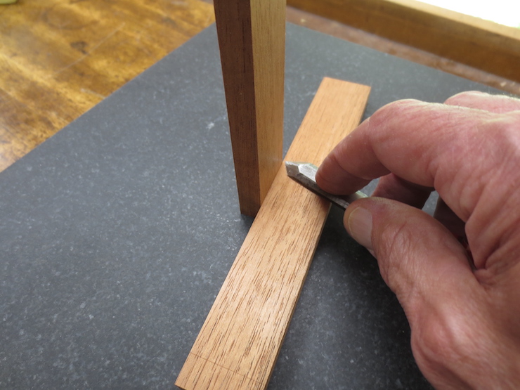
This gauge is used with a marking knife to scribe angled lines for the dovetails. Above, the long side of a mould is being marked on its end for pins; below the short side of a mould is being marked on its side for tails. The longer side of the gauge is always pressed against what will become the top of the mould frame. Since the bottom surface has been left rough, from the saw, it is easy to identify the smooth top reference surface.
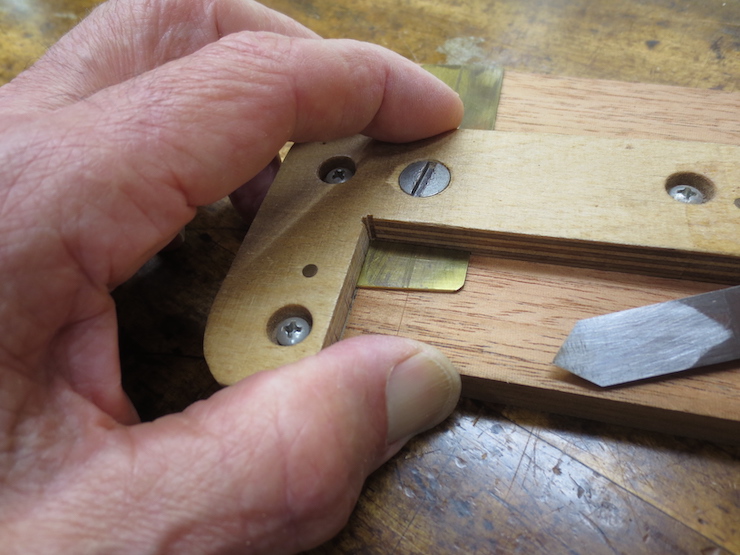
The tails are marked the same on both sides; the pins only on the outside. The tool is carefully set to make a slanted mark that matches up exactly with the previously scribed straight mark (where they meet at the corner). After the tool is set it is used to mark all of the joints being made; pins and tails, often for multiple moulds. After all parts are scribed the brass blade is re-adjusted to mark the second dovetail and the process repeated. Then the blade is flipped to reverse the angle and the process is repeated to scribe the other two sides of the dovetails.
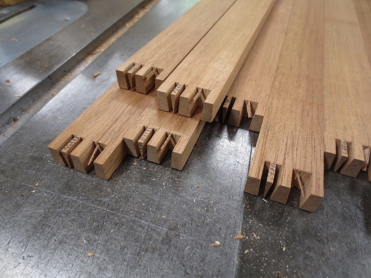
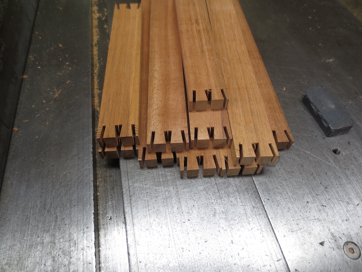
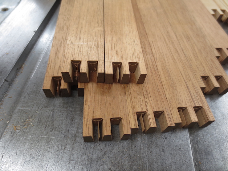
The short pieces which will form the ends of the mould showing the tails marked with parallel marks on their ends and angled marks on their sides.
The long pieces which will form the sides of the mould are marked with parallel marks on their sides (difficult to see) and angled marks on their ends.
Rough out waste wood
I usually make a few moulds at a time. If the joints are identical it is easier to do some of the work by machine. When making one mould at a time it might be easier to do more of the work by hand.
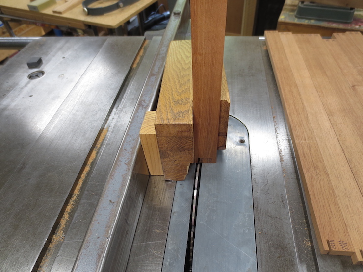
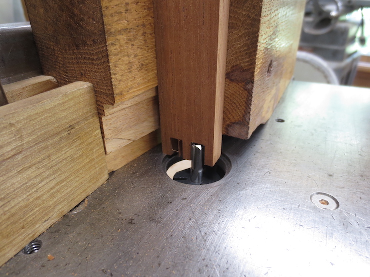
This tool is used to hold the parts straight up at 90 degrees to the table so accurate cuts can be made at the ends using the hollow ground blade. Here a block of wood is screwed to the side of the tool to hold the pieces at an angle that matches the dovetails on the pins (6 degrees here).
You have to keep your wits about you to keep from making mistakes. The pieces must all be oriented the same way with the (smooth) tops on the same side and the outsides facing forward. The fence of the tablesaw is re-set for the cut between each pair of pins. The block that establishes the angle is moved to the other end of the tool to reverse the angle for the other sides of the pins.

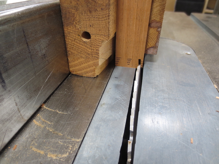
Notice that the scribed lines are still clearly visible. They will be used to guide the chisel when the joints are pared by hand to their final fit.
Removing the block holds these pieces at 90 degrees to the fence. Now the saw is tilted to 6 degrees to cut the angled sides of the tails.
The short pieces on the left are extras. I always make a few shorts that are used as test pieces when making adjustments.
Again, the scribed lines are left to guide hand work.
Machine trim tails and pins
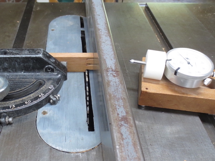
Now the shoulders of the tails are trimmed using the hollow ground blade (now set at 90 degrees). This is not a rough cut; it will be the final cut for this part of the joint. The dial indicator makes it possible to make very fine adjustments. Once the fence is set all of the parts are trimmed exactly the same.
The machine work is finished for the tails.
The space between two pins is being routed out to establish surfaces at the bottom of the joint. The router bit is set to exactly match the thickness of the frame parts. The block of wood at the far left is a stop that is clamped to the tablesaw fence to limit the cut.
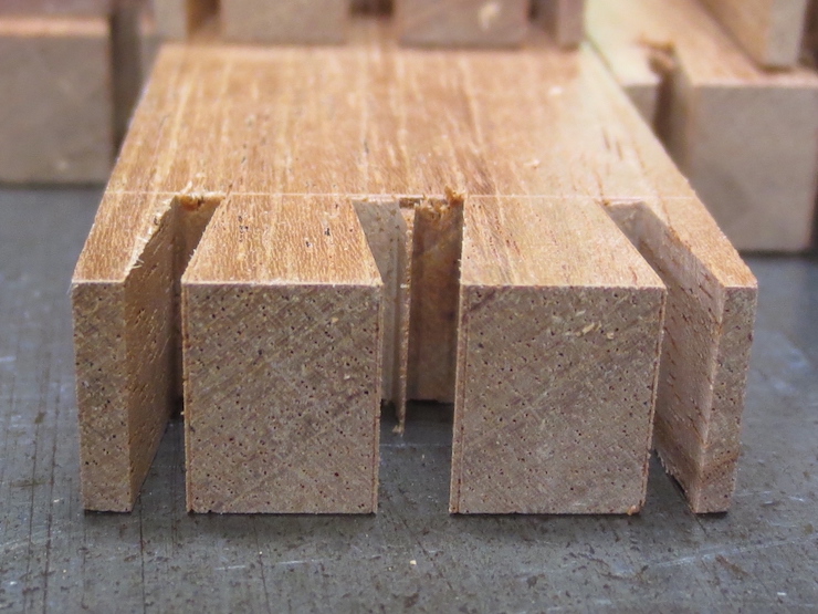
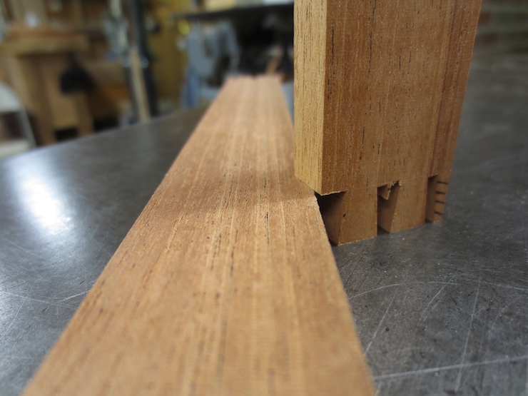
The pieces are only routed out a little bit…
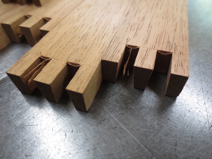
…from both sides. The little ledges make it easy to position the chisel to trim out the bottoms between the pins.
Final fit by hand
Now the joints will be pared by hand using the scribed marks to guide the chisels.
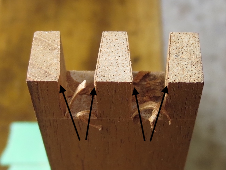
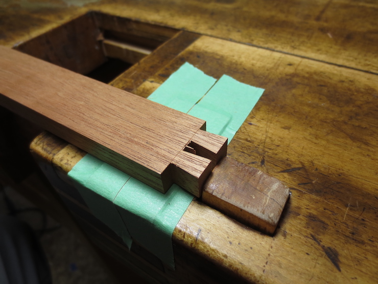
The flats between the pins have been chiseled out using the routed surfaces as guides. These surfaces should ideally be flat but it is more practical to make them ever so slightly hollow. When the back of a chisel is laid flat there it should not rock on any high spots. (Better to have low spots). Using the scribed parallel lines to start the chisel, the sides of the pins are refined, using the slanted lines as guides. The photo above shows two sides just started. The pins are pared from one side only; there are no lines scribed marking the back side of the joint.

The tails are pared in a similar way after the flat between the tails is chopped out at the scribed line. The chisel is started in the angled marks and the parallel marks are used as visual guides. The chisel can be located in the scribed marks partly by feel, though I have to use my head mounted magnifier for most of this hand work. The tails are pared halfway from each side; the angled marks have been scribed on both sides.
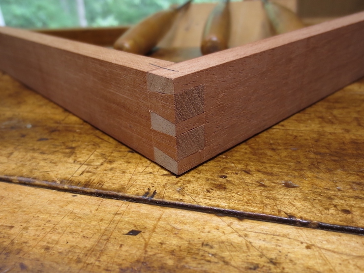
The finished joint. It is usually necessary to pare little bits off here and there to get the joints to fit just right. Some folks would want to cut the joints entirely by machine which is certainly possible. But a slight miscalculation using a machine makes it easy to make a lot of scrap in a hurry. I prefer a safer approach and find it satisfying to do this part by hand.
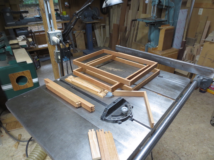
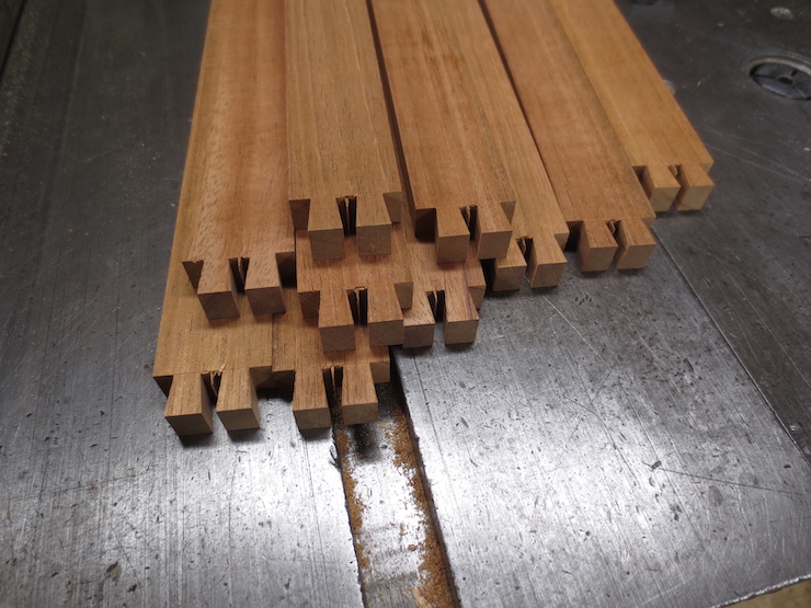
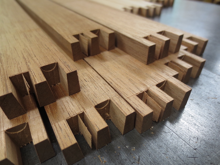
Mould frames after final fitting. There are a few extra pieces here that won’t be used. The four pieces of lighter colored wood are an experiment. They will make an A4 size wove mould made entirely of Larch.
More detail and a few tips.
For most of my career A (the deckle overlap) measured 3/4″ and B measured 1/2″. The total width of the deckle was 1-1/4″. For the space between the mould frame and the inside of the deckle (C) I use .015″. If a mould was to make a sheet 12″ x 18″ the drawing would work like this: For the short side 12″ (N) would be added to twice the deckle overlap (A) to give 13-1/2″. From this twice the desired space (C) is subtracted. The result for the two shorter frame pieces would be 13-1/2″ minus .030″. Calculating the length of the deckle pieces is easier; they would measure 12″ plus twice the deckle width (2-1/2″) or 14-1/2″. The same calculations are made for the longer pieces, substituting 18″ for 12″ at (N).
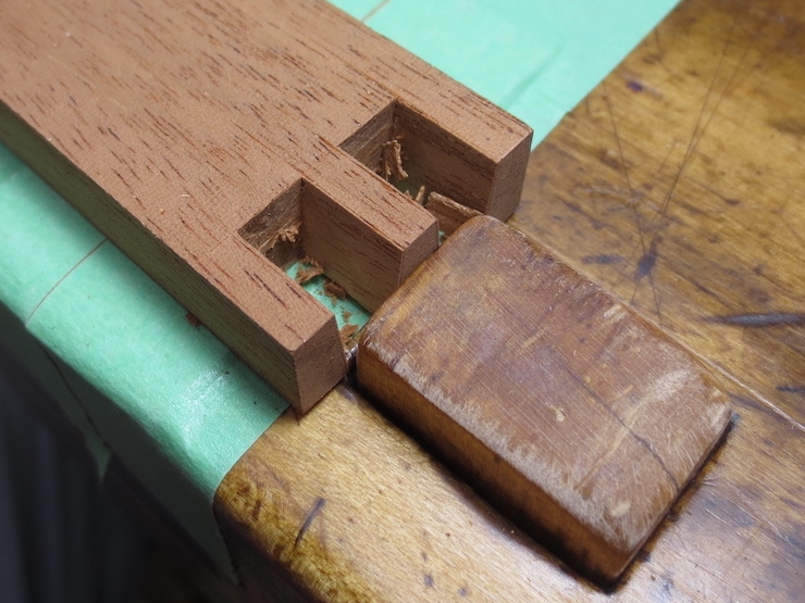
This measuring tool is better than using a tape measure. The beam is scribed in 1/2″ increments and should be long enough for your largest mould. The small block with white plastic guides is clamped so that its near end aligns with the desired mark. The trimmed end of a mould part can be pushed against the block on the left and scribed at its other end for an accurate measurement.

Here the tool is set to mark the long side of a 12″ x 18″ mould so the moveable block has been set for exactly 19-1/2″ (using the above calculations). The .030″ shim reduces the length to create the .015″ space at both ends.

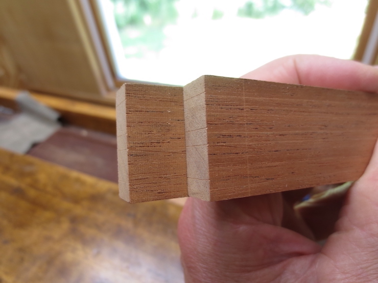
This is a rough piece of wood, used as an example. But if it were an actual frame piece the left end would contact the shim. This would reduce the length by the desired .030″ when the length is scribed as shown here.
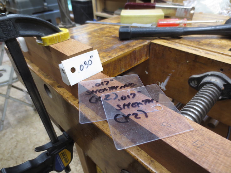
If the mould is to be sheathed with brass sheet two additional shims are added. They are the same thickness as the brass that I use (.017″)
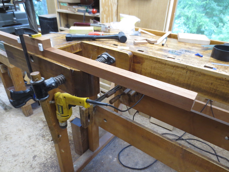
The saw is being set to cut at the scribed mark made using the measuring beam. If the deckle pieces and mould frame pieces are all measured with the same device the results are more predictable and the fit is likely to be better.
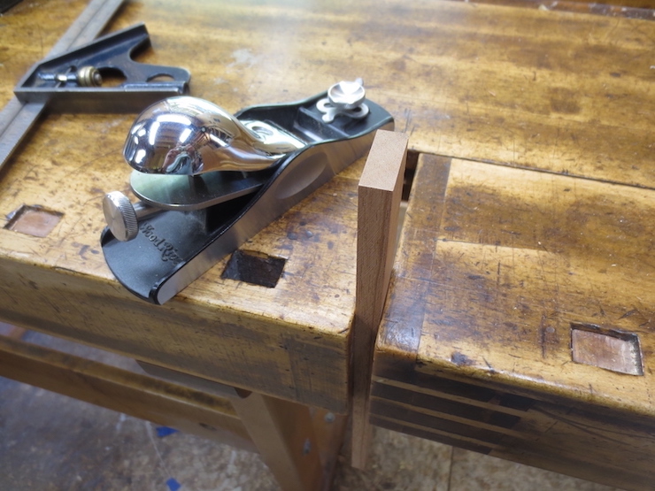
Since I use epoxy to glue the joints they will be rigid. If slightly out of square pieces are clamped and glued they will likely force the frame out of flat. To avoid this problem any out of square pieces can be corrected with couple of swipes using a block plane and the method below.

The blade is very sharp and set for a fine cut. The middle is planed hollow as shown above. Then the bed of the plane behind the cutter is set firmly down on the low side and a fine cut taken off the high side. Check for square and repeat if needed. This adjustment only needs to be made for the longer dimension as shown above. The short dimension isn’t as important.
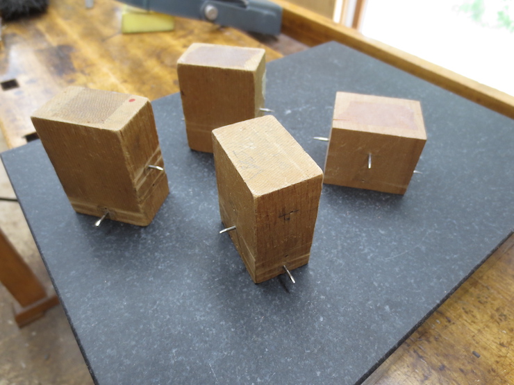
Different dovetail spacings each need a scribing block.
When trimming the shoulders of the short sides you can check the fit like this.
Raising the saw just enough to score barely across the scribed lines leaves a visible line that helps when paring the sides of the tails.

Before routing between the pins the router bit is set at exactly the thickness of the mould frame pieces using the dial indicator.
Note: (This batch of small moulds is made with different dimensions than my old standard; the frame pieces are 7/16″ thick (.437″ on the dial indicator shown above). For years the small moulds I have made seemed over-built. I now make smaller moulds a little lighter. These moulds have 11/16″ deckle overlap, 1-1/8″ x 3/4″ deckle parts. The frame parts measure 7/16″ x 1-1/8″. The ribs are 5/8″ deep with 3/16″ diameter pegs. The space between mould and deckle stays the same at .015″ all around.)
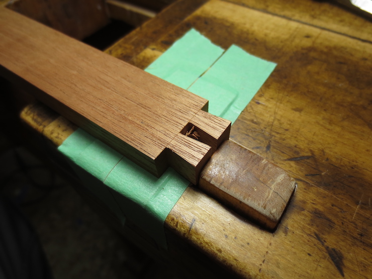
These routed ledges make it easy to trim the bottoms of the joints flat between the pins.
The frame piece dogged flat on the bench for trimming between the pins.
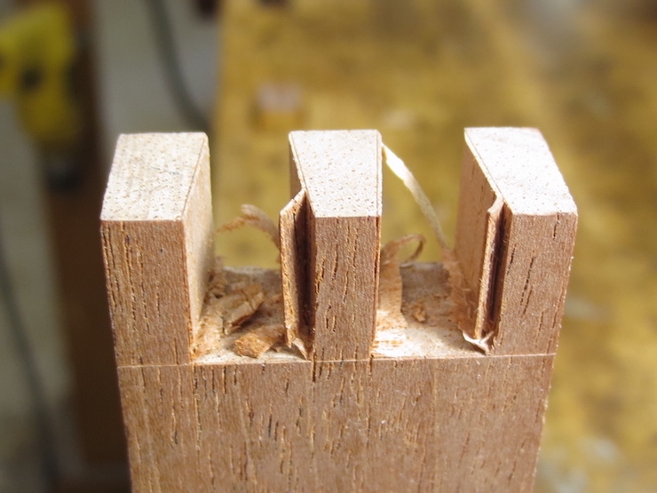
The joints of the pins are not scribed on the inside. Chiseling off these corners keeps the chisel from splitting them off when the joint is pared from the other side.
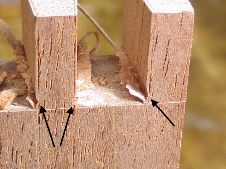
It helps to cut these grooves (with a small chisel held at an angle) before paring the sides of the pins. Then the chisel is kept just above these grooves so the parings can easily fall away. If the grooves aren’t there the uncut fibers of the wood at the bottom will pinch the chisel there making it harder to control. The corners can be cleaned out after sides are made flat.
A sharp chisel’s edge can be started right in the scribed line…
…and pushed straight down to trim between the tails. The piece is flipped and the process repeated from the other side.
With a little careful guidance (and visual magnification) a sharp chisel will seem to find its own way into the scribed lines to start the paring cuts.
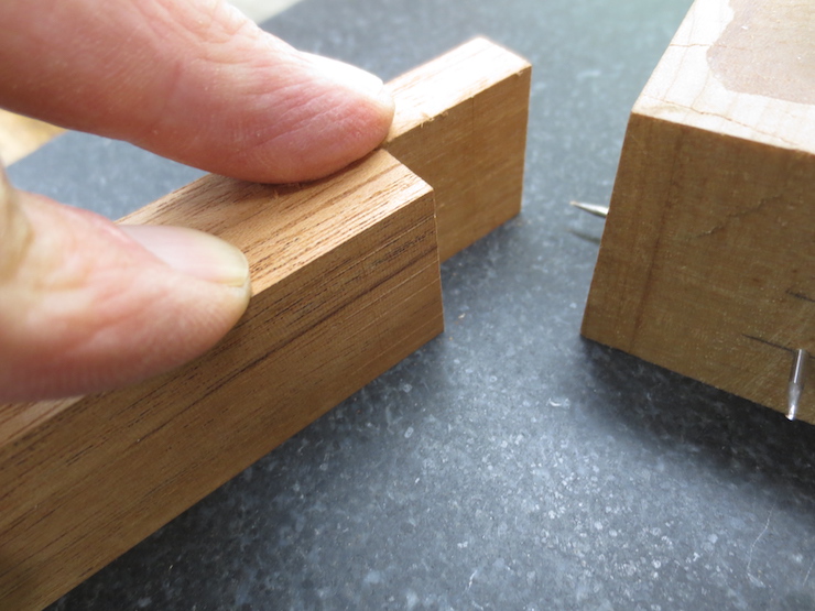
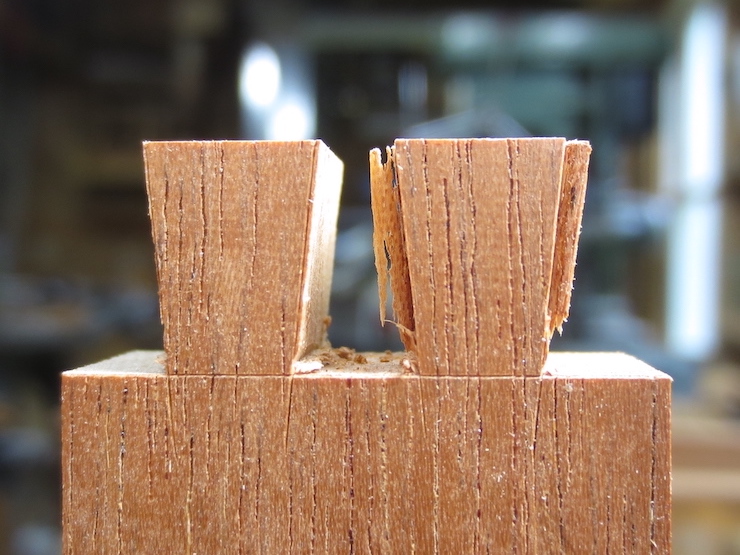
A finished pair of tails.
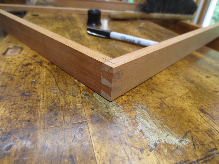
Pins and tails fit together to make a very strong joint.
