First Step: Dial In the Drill Press Table
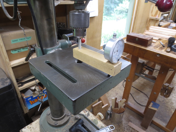
This drill press has a table that can be tilted and is prone to getting out of alignment. A dial indicator mounted in the chuck can be rotated by hand to check this. Small taps from a dead blow hammer are usually enough to correct misalignment. If the spindle is not true to the table (90 degrees in all directions) the holes drilled for rib pegs will tend to push the ribs out at odd angles. This introduces tensions into the structure that may throw the mould out-of-flat and/or out-of-square.
Setting the Drill Press Fence
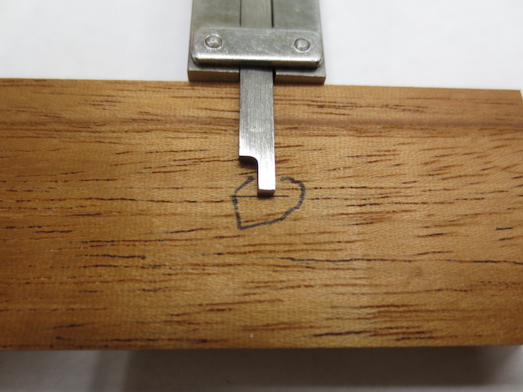
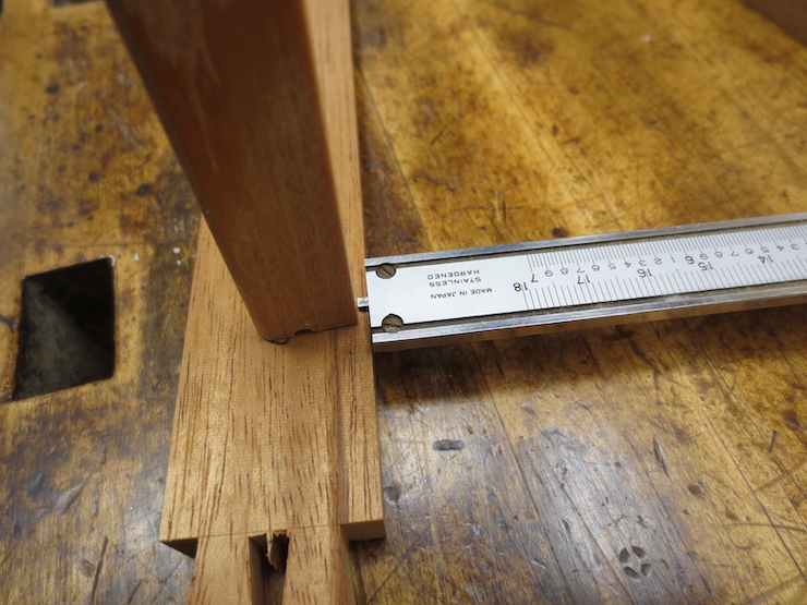
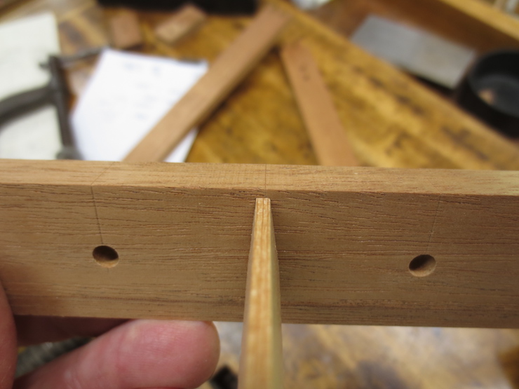
The center of the rib peg hole, having been calculated, is scribed onto a test block, usually an off-cut or extra piece from the batch of moulds being made.
The hole to be drilled here (in this test piece) has been calculated to make the narrow top edge of the rib end up high by about .010″. This bit of extra wood will allow the ribs to be leveled after the mould has been assembled. Different types of mould will require the ribs to be set at different levels. This is to account for the differing arrangements of laid, bridge and chain wires that will rest on and be sewn down to the ribs. Drawings at the bottom of this post may make this more clear.
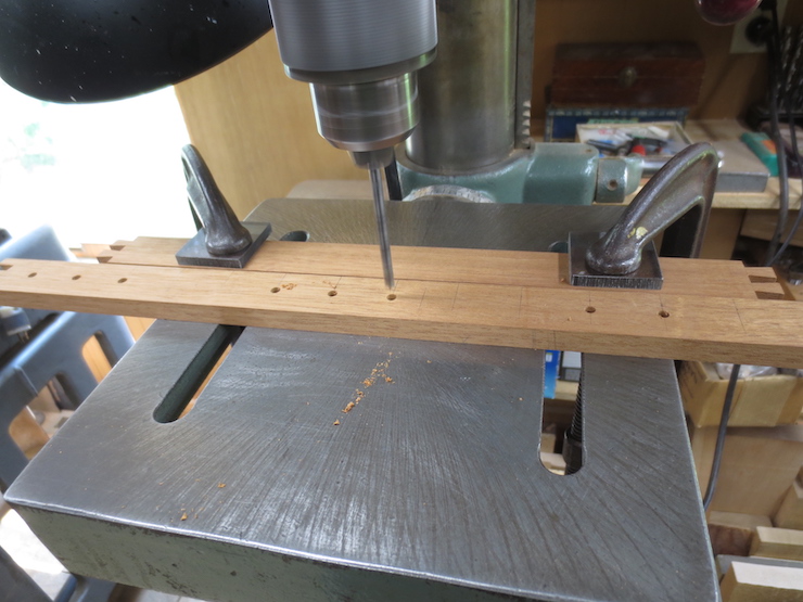
A fence is adjusted by eye to drill to the center of the mark. It is clamped to the table with two C-clamps and a test hole is drilled with a brad point drill.
A rib is inserted…
…and the depth of the recess is checked. The drill press fence is then re-adjusted as required before drilling the holes in the actual frame pieces.
Drill the Rib Holes
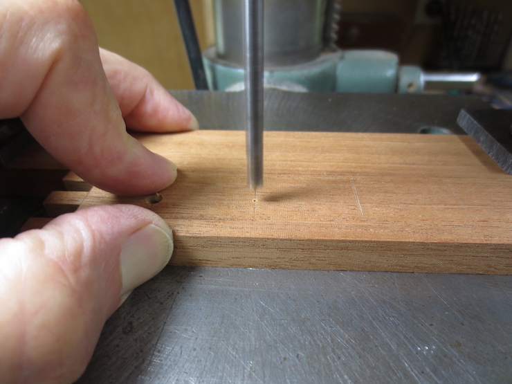
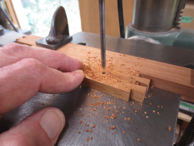
Try to put the point of the drill exactly in the middle of each mark. I sit on a chair so my eyes are nearly at the level of the table and use magnification to see better.
The top edge of the mould frame piece rests against the fence. The hole is drilled from the inside of the mould where the marks have been made. The depth stop of the drill press is set so that only the sharp point of the drill pokes through the other side.
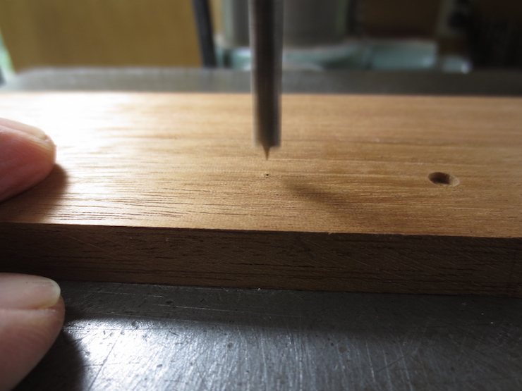
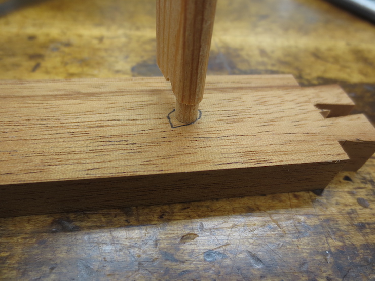
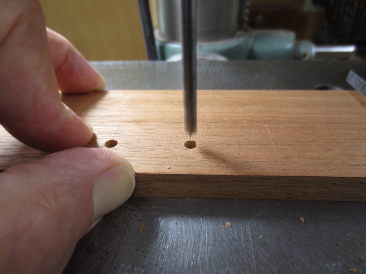
The frame piece has been flipped over to show the tiny hole created by the point of the drill. Using the fence, the piece can be positioned so that the drill point will seek the hole to finish drilling from the other side. This way the hole can be finished neatly without tear out.
As mentioned in a previous post some moulds have blind holes that don’t pass completely through the frame. In my way of thinking a through hole is better. I have repaired old moulds where the shorter blind rib ends weren’t adequately pinned to the frame, allowing the frame sides to spread apart. I also think that a mould with full length rib pegs might dry out a little more quickly after use, possibly helping to prevent decay. There are no concealed pockets to trap moisture (after any amount of use all parts of a mould will be thoroughly soaked) and the exposed end grain of the ribs may actually help wick away the moisture that has accumulated. Moisture enters and exits wood more readily through end grain than it does across the grain.

The sides of the frame are lightly sanded to catch and remove any ragged fibers around the edges of the holes.

Finished rib holes.

A rib seated in its hole in the frame.
The same rib from the other side.
When inserted the ribs should be held square to the frame. Individual ribs will usually curve slightly one way or the other. Turning a rib 180 degrees and checking it twice from the same side will reveal this. If the variation from square is the same both ways the hole is drilled perpendicular to the frame. If not the hole may be slanted.
Waterbar notches

A waterbar is a small extra rib that lies closely along the short ends of a mould. The wires of the mould aren’t sewn to it, it just touches the bottoms of the wires that cross it. Notches are routed into the frame to hold the ends of a waterbar. In Britain what I call “ribs” are called “bars”. So “waterbar” might translate to “water rib”. This could be a shortening of the awkward-to-say “de-watering bar”. These little ribs are intended to improve drainage along the short ends of a mould just under the edge of the deckle. Ribs provide pathways for water to flow down and away from the paper being formed on top of the porous wire facing. Including theses small de-watering ribs makes sense for single-faced moulds. These moulds suffer from poor drainage in the areas between ribs so the fibers are deposited on the wires there in a thinner layer. Thicker areas, known as ‘shadow zones’ form along the ribs where drainage is improved by the presence of those ribs. It follows that an extra rib positioned right under the edge of the deckle might improve drainage and help to form a substantial deckle edge there, too. But I’m inclined to think that waterbars are not needed for double-faced laid or wove moulds. In these moulds a layer of backing wires provides more pathways for water to flow along. This more complicated wire structure improves drainage and makes formation very even over the entire top layer of wires and eliminates the shadow zones. I would argue that no extra help from waterbars is needed for these moulds that include an extra layer of wires. Many people make their own wove moulds which must have backing wire of some sort to function well. Most, if not all of these moulds do not have waterbars and don’t seem to need them.
(Though I have long suspected that most waterbars are ‘vestigial’ and unnecessary I do not follow my own advice. Waterbars are still found on all of my moulds.)
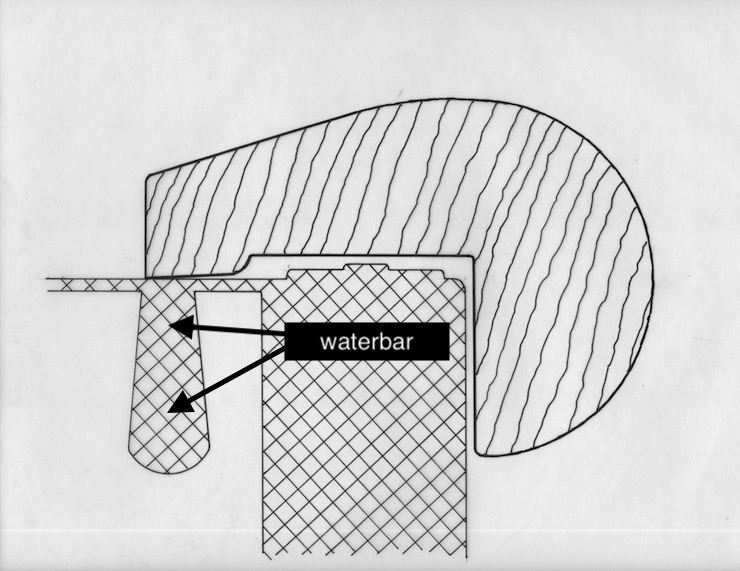
This drawing shows the waterbar and how it relates to the inner margin of the deckle.
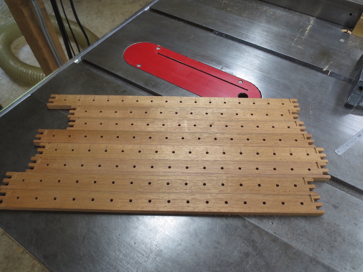
Mould sides drilled and ready for assembly.
Drilling Sequence
Because the drill leaves a little bump where its point exits the other side of the mould frame I drill only every 5th hole in a pass. This way the bump will hang over the edge of my drill press table and can’t affect the alignment of the next hole as it is drilled. Here I’m on the third round having just drilled the 3rd and 8th holes. (The gap visible between the work and the fence is not normal. My hands are holding the camera and the piece has shifted on the table.)
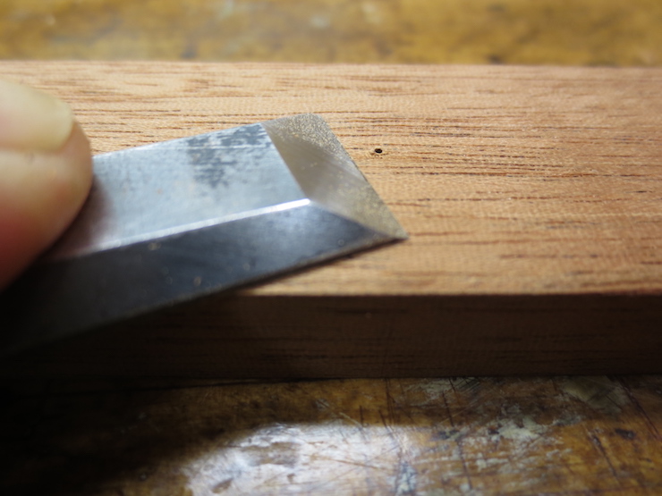
I don’t like the idea of the bump preventing the frame piece from resting completely flat on the drill press table (having already gone to the trouble of aligning it with the dial indicator). When a side is 1/5 finished I pare off the bumps on the back. Then the piece is returned to the drill press to repeat the process with the next several holes, again every fifth hole (depending on the size of the drill press table). This process isn’t difficult and doesn’t take significantly longer. This is just one more detail that’s intended to improve the outcome.
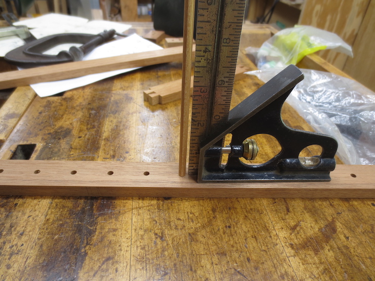
Making Fine Adjustments
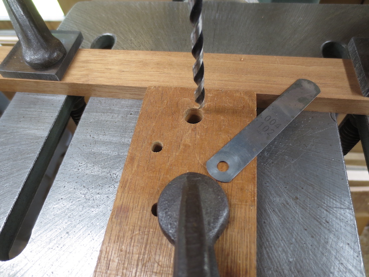
When setting up the drill press the first hole drilled into a test block inevitably needs to be moved a little closer or farther from the top edge of the frame. Here is a simple way to accurately re-position the fence. In the photo I’ve clamped a scrap block of wood with a true flat end tight against the fence. After loosening the two clamps that secure the fence an appropriate shim can be inserted. Then the fence is pushed up tight against the shimmed block and the C-clamps re-tightened, re-positioning the fence BACK by exactly the thickness of the shim. Block and shim are then removed. If the shim is placed FIRST (before clamping the block in place) the fence can be moved FORWARD after the shim is removed.
Waterbar Notches

After waterbar notches have been made in one end of all of the mould frame pieces the stop (shown here clamped to the tablesaw fence) has to be moved to the other side of the router bit.

This is because the notches must be cut from the opposite direction on the other end(s).
Placement of Ribs for Three Types of Mould
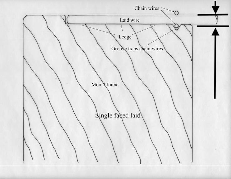
A single faced laid mould will have the ribs set very close to the top of the mould frame. After the tops of the ribs are leveled they should be lower by a little more than the diameter of the laid wires. The level described by the top edges of the ribs is indicated here and in the two drawings below by the lower line and arrow. The upper line shows the top edge of the frame.
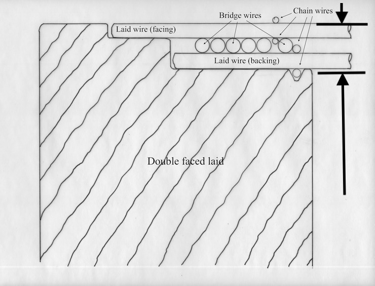
For a double faced laid mould the tops of the ribs should be set considerably lower as shown above.
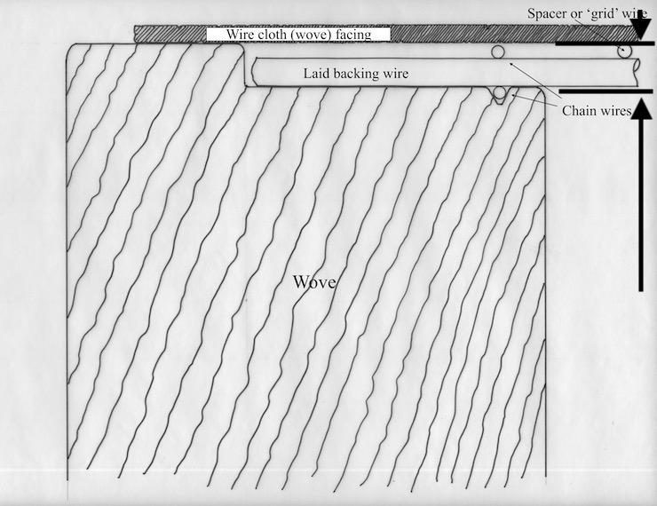
The edges of the wire cloth wove surface generally rest on top of the mould frame. The ribs of a wove mould need to be set at a level to accommodate the diameters of the backing and bridge wires that support the wove facing.
