Before the corner joints of a mould are glued one or two brace rods must be fitted. One for smaller moulds, two for larger ones. They will pass through all the ribs and be anchored in the frame at both ends. Waterbars also need to be fitted along the ends of each mould.

The waterbars are really just little ribs and have the function of helping to draw water away to help form a good deckle edge. They are made in much the same way as the regular ribs. I straighten them and cut them to size in only one sequence of steps, unlike the ribs which have been reduced and shaped in two sequences. This might make more sense after reviewing the post on making ribs.
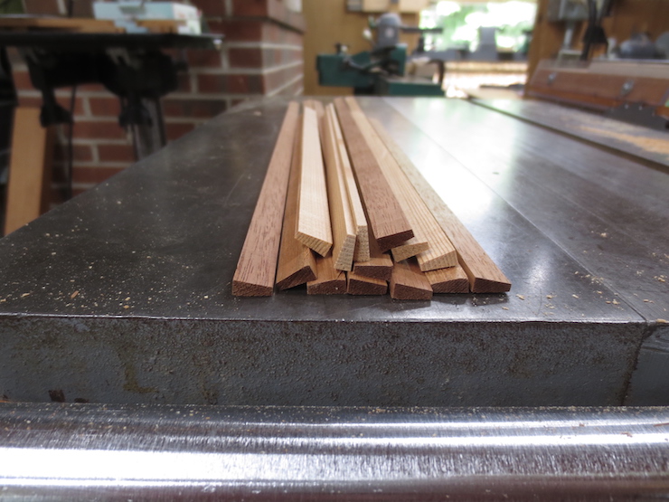
A by-product of roughing the deckle parts to an “L” shape are small strips of wood just right to make waterbars from. The straightest of these scraps were saved to make these waterbars. The lighter colored ones are for the experimental wove mould that is being made completely of Larch.
The bottom edges are rounded just like the ribs were.
These are ready to be cut to length and fitted into notches in the mould frames. They have tapered sides and rounded bottoms like ribs but do not need pegs formed on the ends.
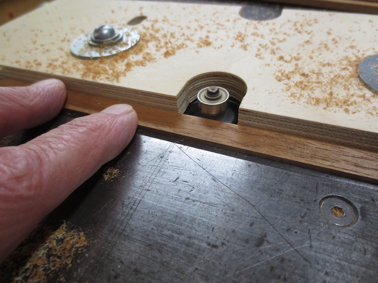
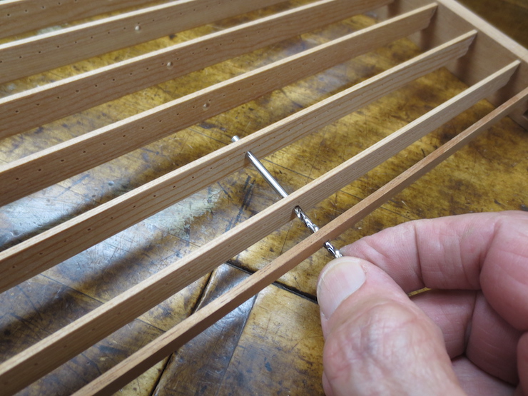
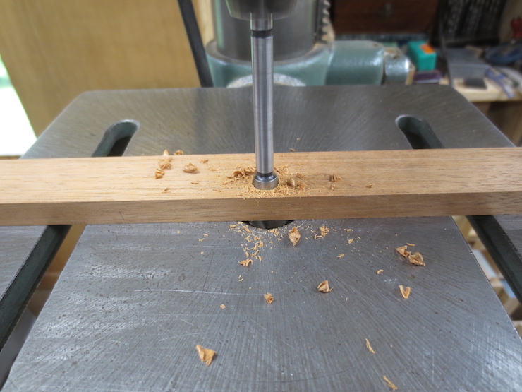
Instead the ends are slimmed down with a block plane to fit into shallow mortises previously routed in the frames. Here a waterbar has been fitted into place and a brad point drill is being used to mark the location of a hole that needs to be drilled for a brace rod.

The brad point drill is turned with the fingers until the wings score the wood.
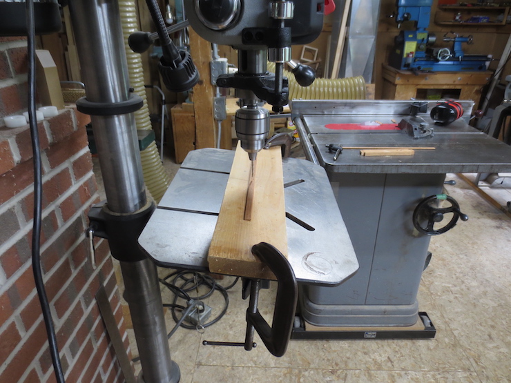
The sides of the waterbars are tapered so the table of this drill press is tilted to drill the hole at an angle. Using the same brad point drill to mark and then to drill is a good idea.
Fitting a Brace Rod
1/8″ diameter brass rods are used to brace the ribs. They are threaded on both ends so larger diameter acetal plastic ends can be screwed on.
Here, a 6-32NC threading die has been embedded in a block of wood with a 1/8″ diameter guide hole drilled through to the other side. The rod is held in the lathe chuck as the die is turned by hand. The power to the lathe is disconnected.
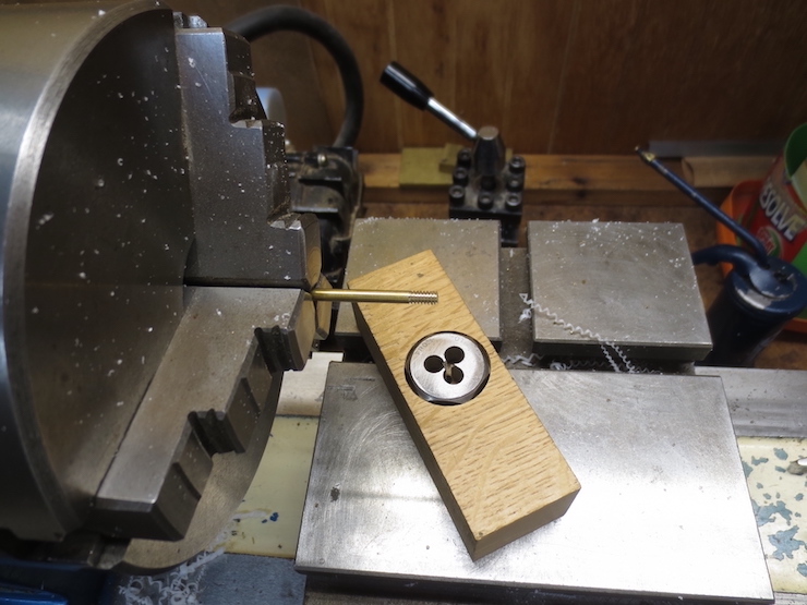
About 1/4″ of the ends are threaded.
In old moulds these rods are often hammered flat and inserted into slots chiseled into the ends of the mould frame. A small pin at each end anchors them in place. Until recently I glued the ends into same-size holes and then drilled for a 1/16″ diameter pin after the glue was set. This works but is tricky; it’s not easy to ‘hit the target’ and the brass shavings enlarge the hole in the wood as they are carried away by the flutes of the twist drill. And it is easy to break a drill this small. Now I prefer the method described in this post.
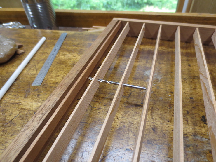
A brad point drill is backed into the holes in the ribs and waterbar in order to mark the place where a hole needs to be drilled into the frame.
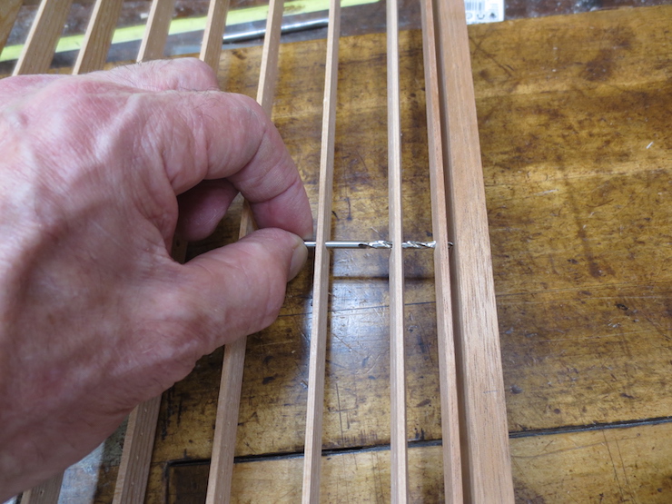
In these moulds the brace rods pass through the waterbars. This is a recent innovation of mine to accommodate the narrow ribs in these small moulds. In larger moulds with deeper ribs (and all other moulds I’ve seen) they are not drilled this way. Usually the waterbars are added after the mould frame is complete. They rest on top of the brace rod(s) and are bound to them with wraps of wire.
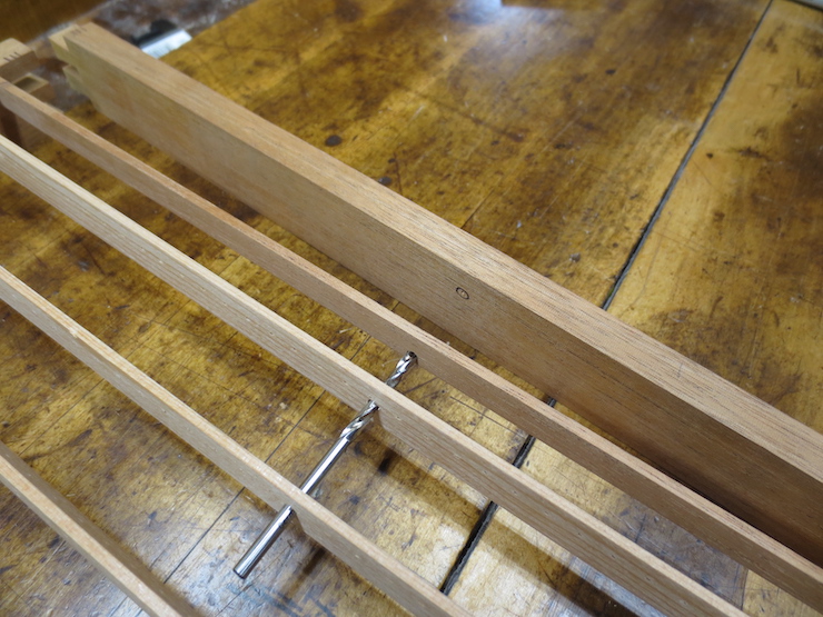
The end of the frame is removed to be drilled after the point of the drill has marked it. The inked circle makes the mark easier to see in the photo.
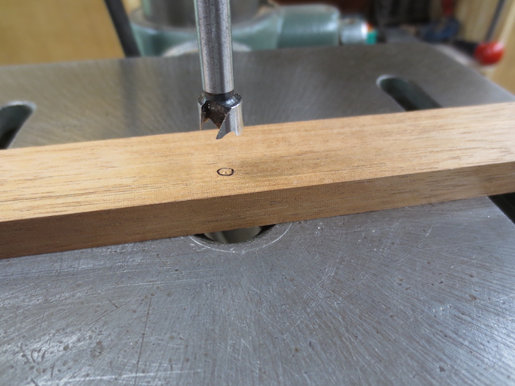
A 3/8″ diameter hole is drilled to fit the acetal plastic cylinders that will be threaded on to the ends of the brace rod. To start the drill I lift the wood up and feel that the point of the drill is in the small hole. (This with the drill press turned off.) Next I move the drill down with the feed handle to push the wood gently down onto the table. Then the motor is switched on to drill the hole.
A forstner bit drills a clean, flat bottomed hole; good for this purpose.

The hole is drilled about 3/4 of the way through.

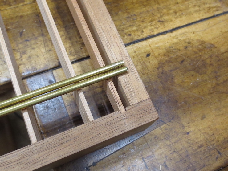
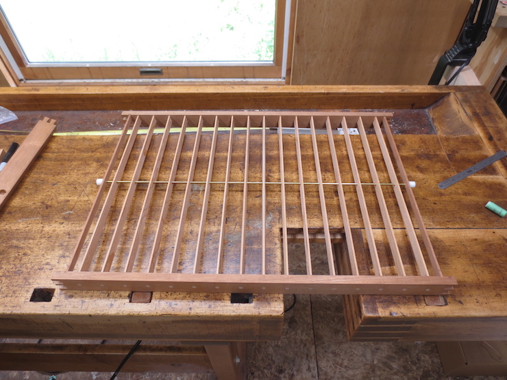
The brace rod is inserted through holes previously drilled in the ribs.
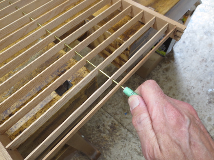
A piece of plastic rod is threaded onto the end of the rod as a sort of wrench. It is used to twist the brace to even it up at the ends.
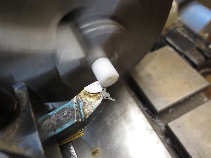
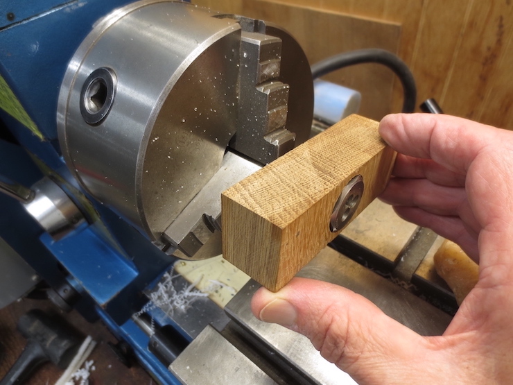
Fittings for the brace rod ends are prepared. Pieces of acetal plastic rod have been cut and surfaced at both ends to about 3/8″ length. Smooth 1/8″ diameter holes have been drilled 1/8″ deep and smaller (#36) holes have been drilled all of the way through and threaded with a 6-32 NC tap. Here the outside diameter is being reduced to fit into the 3/8″ hole drilled into the wooden frame. (The acetal rod is manufactured slightly oversized to allow for machining.) For this operation the fittings are threaded onto a scrap piece of threaded brace rod that has been chucked into the lathe.
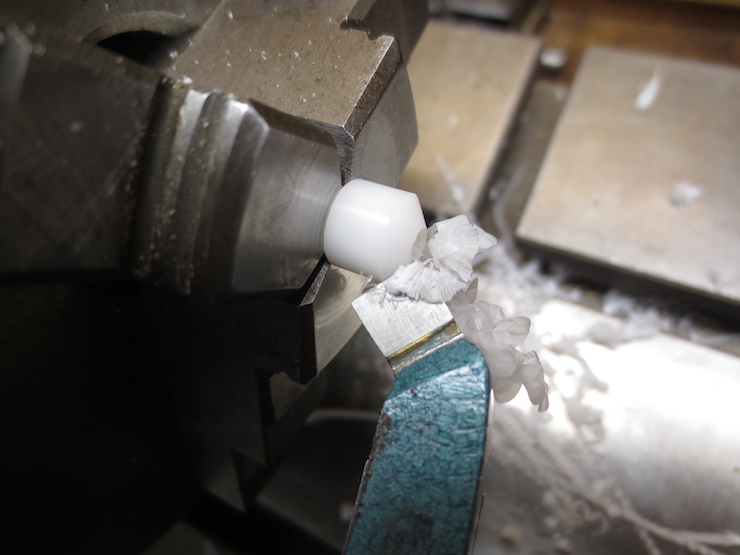
The inner end of each is beveled. The waterbar will rest against this end. The length of the fitting and the depth of the hole in the frame are calculated so the waterbar will end up being held at the right distance from the frame.
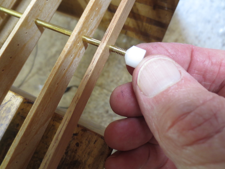
A fitting is threaded onto the brace rod at both ends.
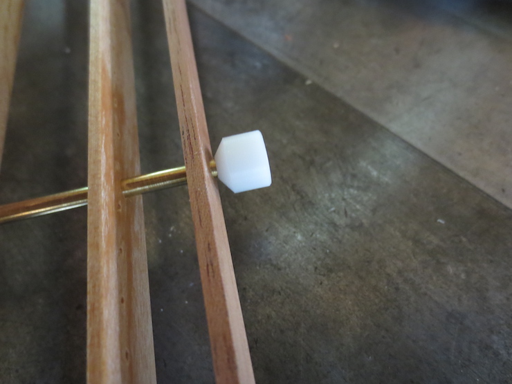
The plastic fitting has a couple of advantages. It strongly secures the brace rod to the frame and holds the waterbar away from the inside of the frame. Waterbars can slide along the brace rods and often shift out of place.
The ends can be adjusted by screwing or unscrewing them a little to make the overall length exactly right so the ends of the frame won’t be bowed in or out.
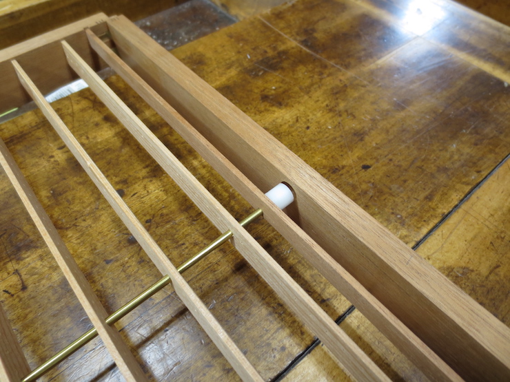
The frame joints and the brace rod ends are ready to be glued with epoxy. After the epoxy has set a 1/16″ diameter hole will be drilled down through the wood and plastic (slightly to one side to just miss the brass rod). A brass pin is then tapped into the hole to make the connection even more secure.
