#23 Sewing a Double Faced Laid Mould

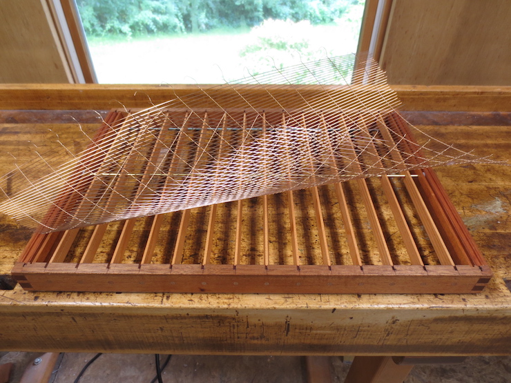
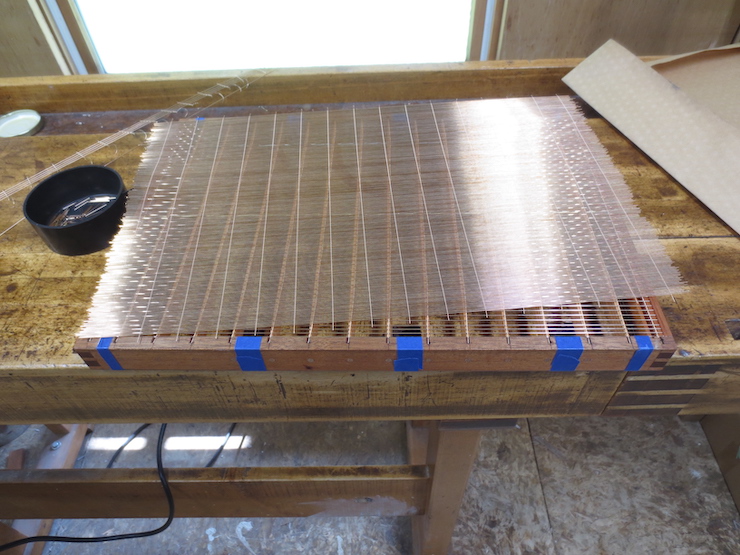
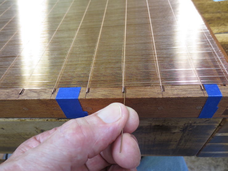
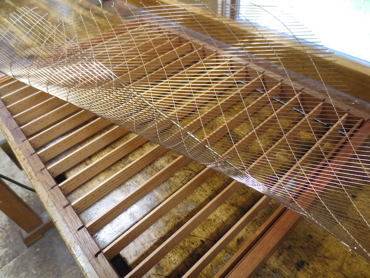
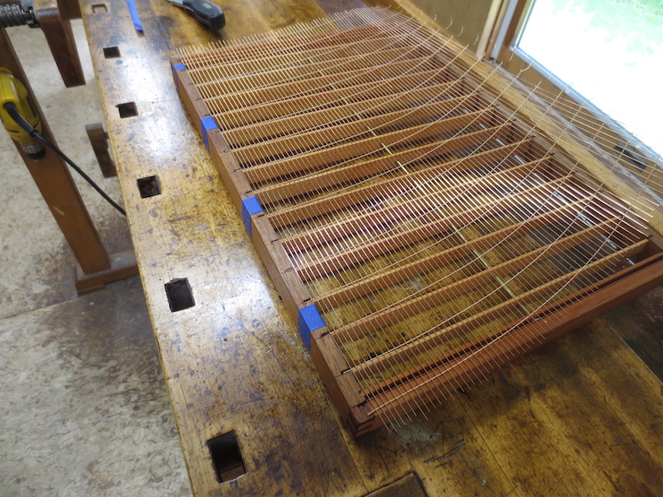
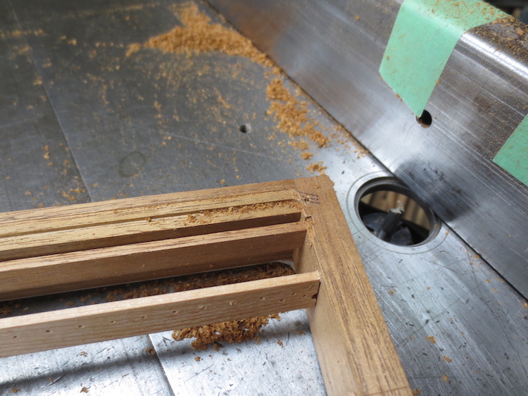
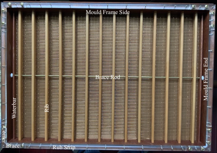
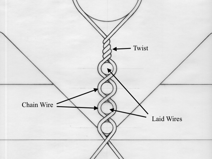
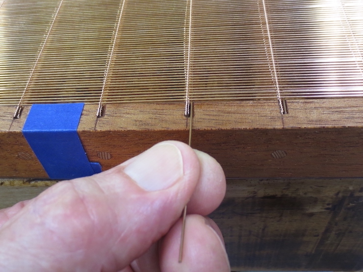
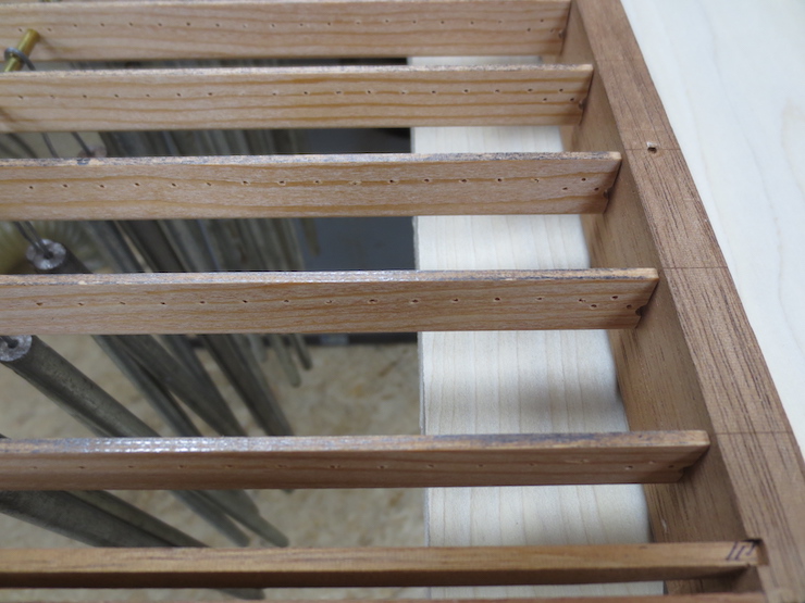
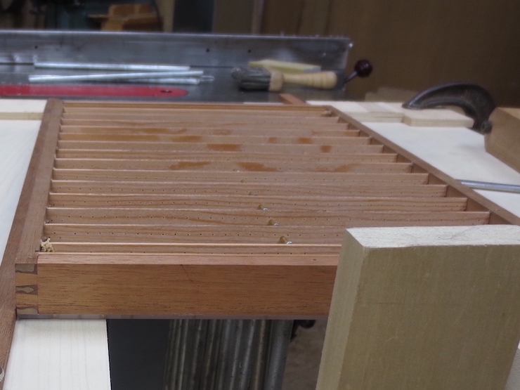
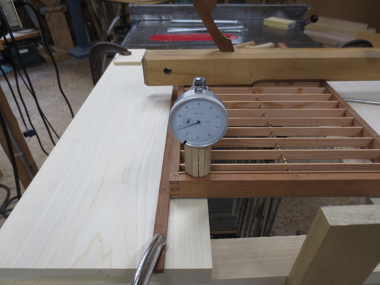
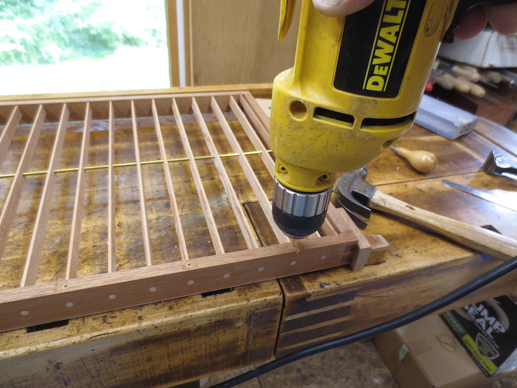
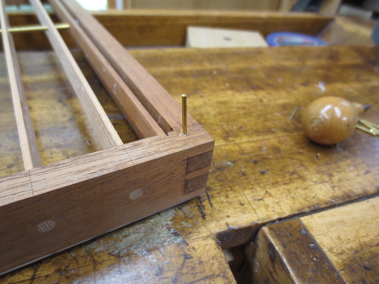
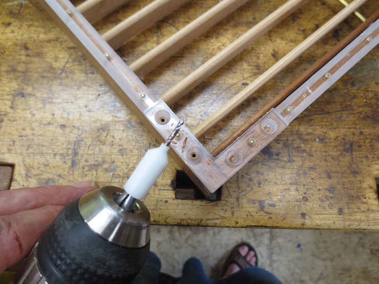
Backing and facing wires have been fitted to this mould; the next step is to sew them to the ribs. A soft (annealed phosphor bronze, in this case .010″ diameter) sewing wire follows a spiral path for the length of each rib to bind the wires to it. The ribs have been drilled at regular intervals to put a stitch in every sixth space (over the chain wire between pairs of laid wires) except at the ends where the stitches are closer.

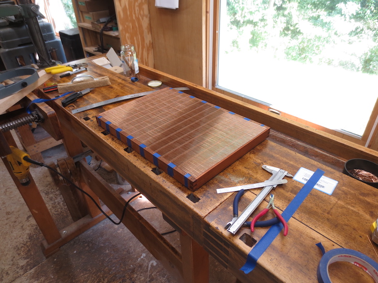
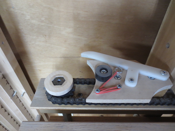
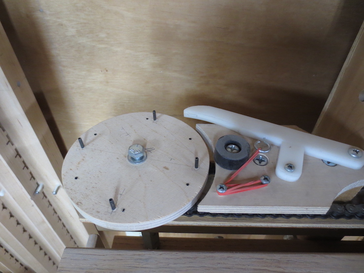
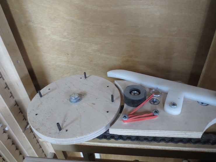
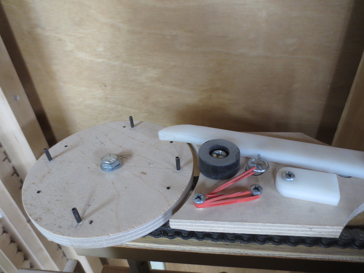
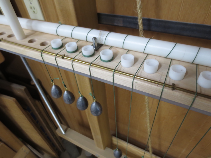
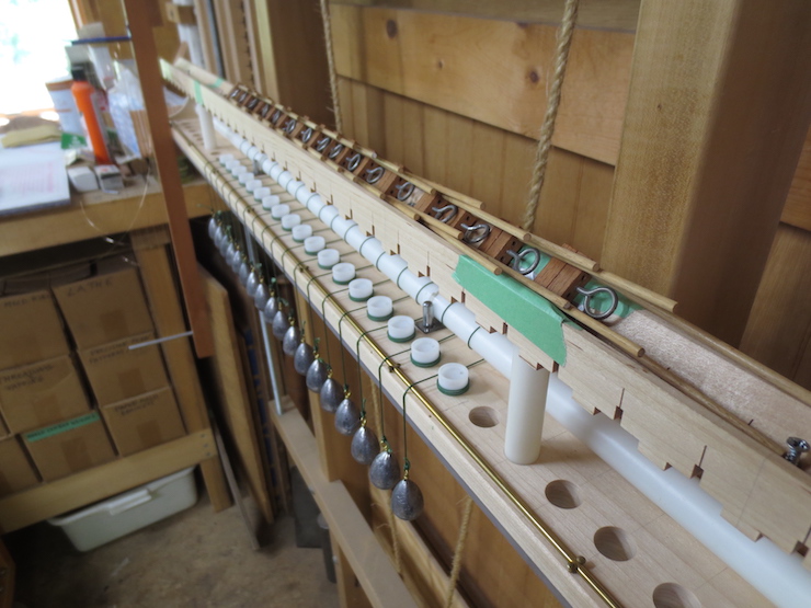
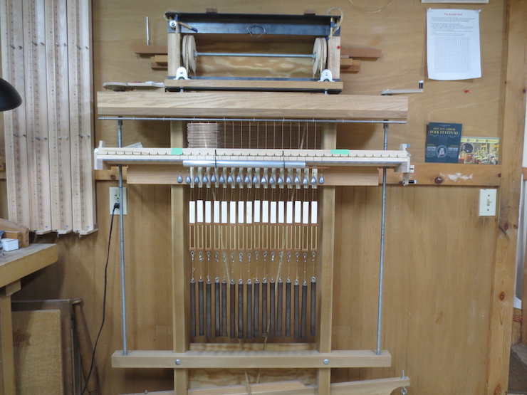
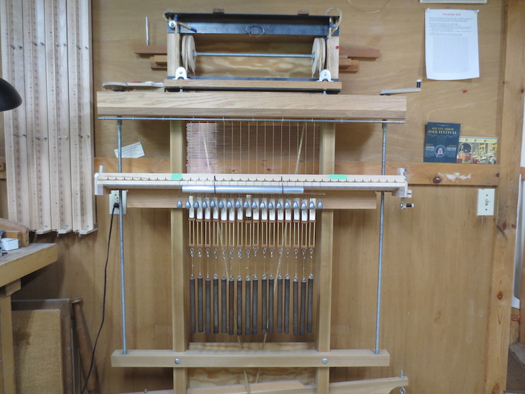
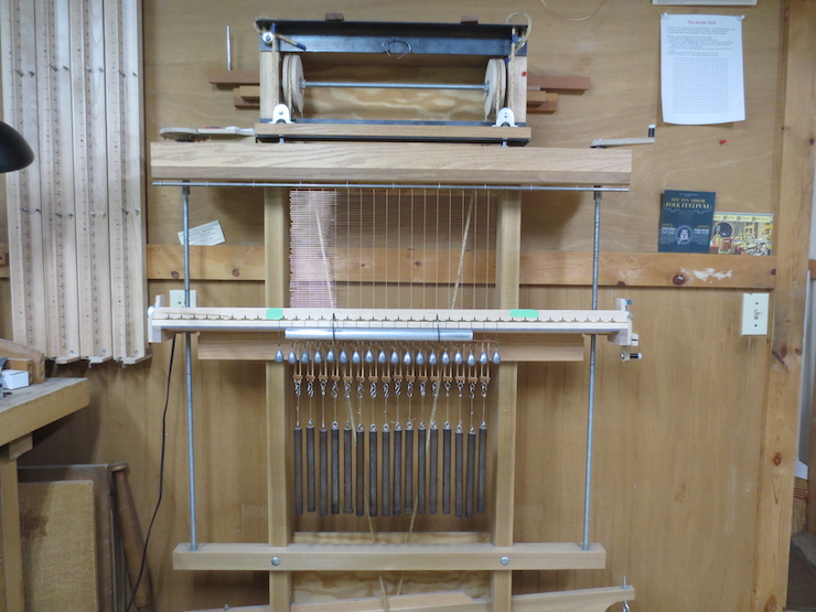
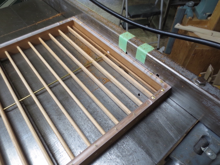
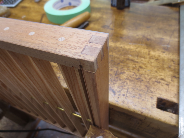
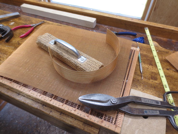
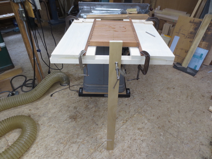
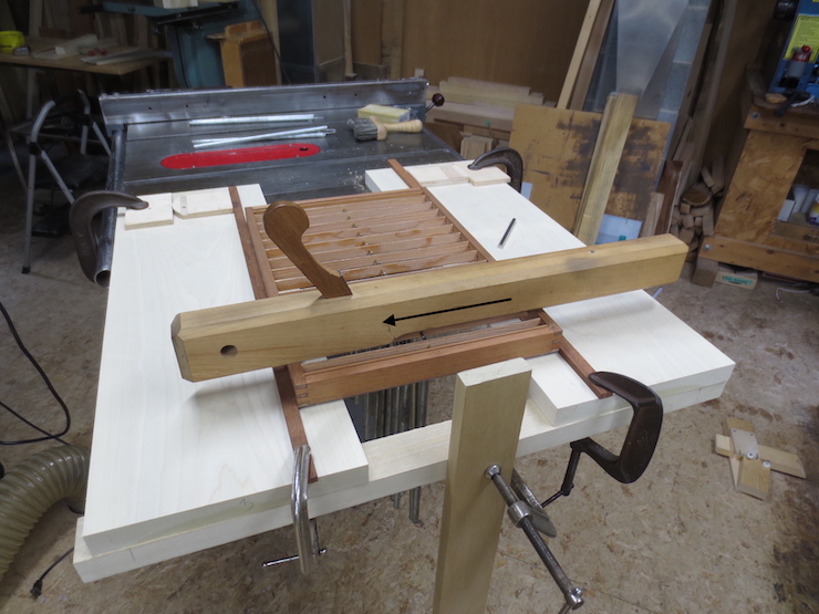
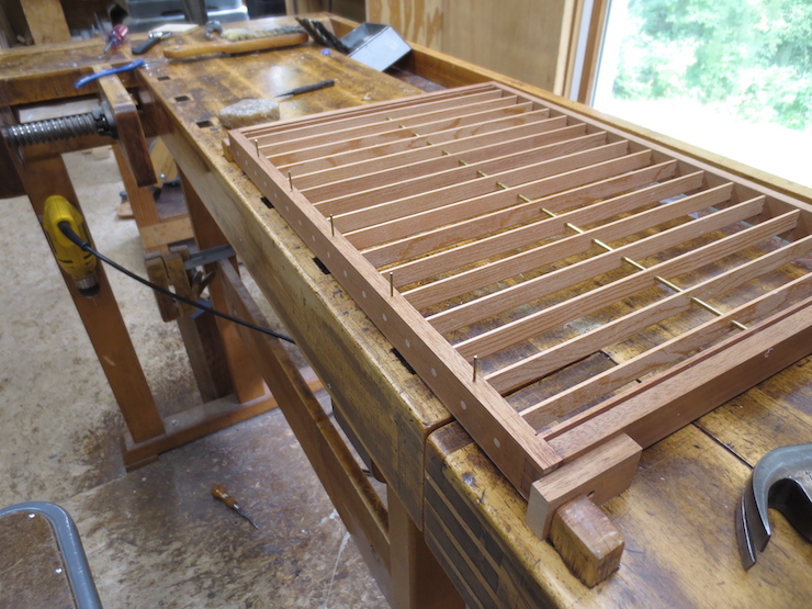
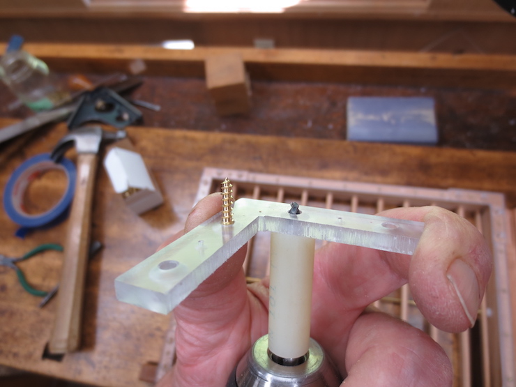
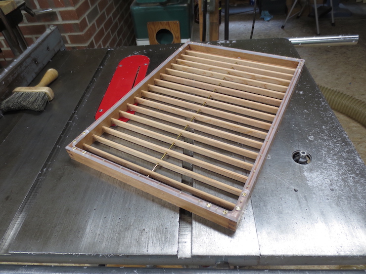
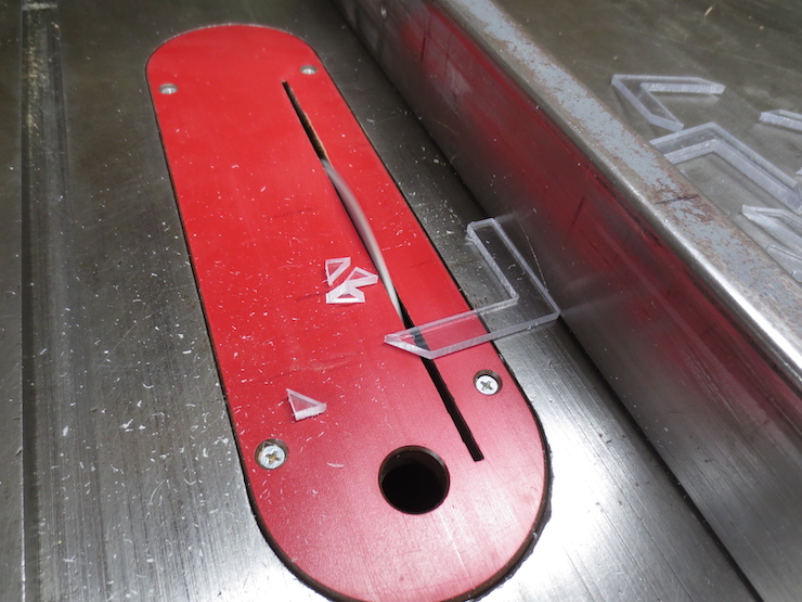
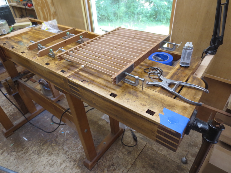
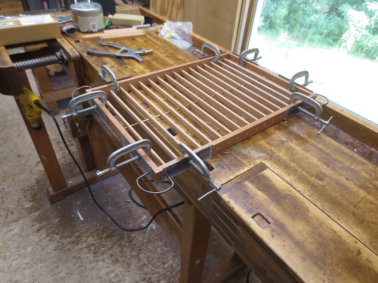
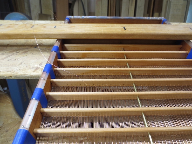
This ‘sewing frame’ (for lack of a better name) holds the mould leaving both hands free to handle the sewing wire. The height can be adjusted for sewing laid or wove moulds. The angle of the mould can be changed easily by loosening the two wooden handles at the ends. When not in use the frame can be folded flat (or taken to pieces) for storage.

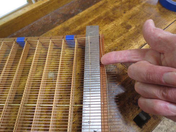
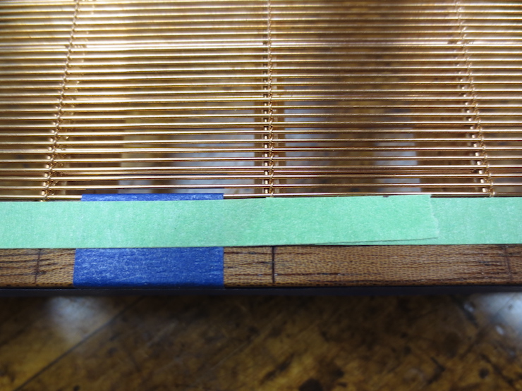
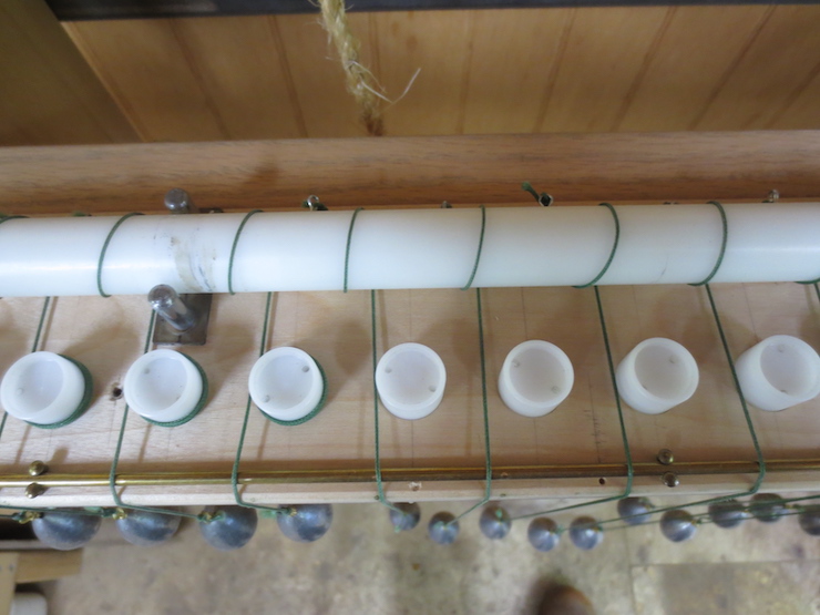
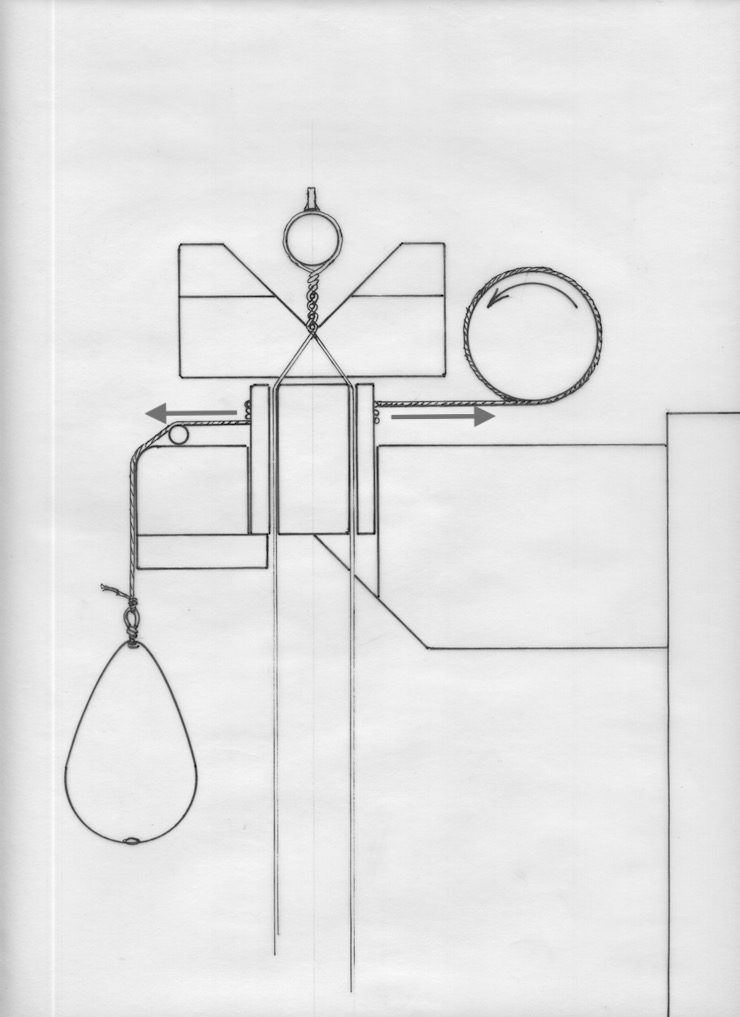
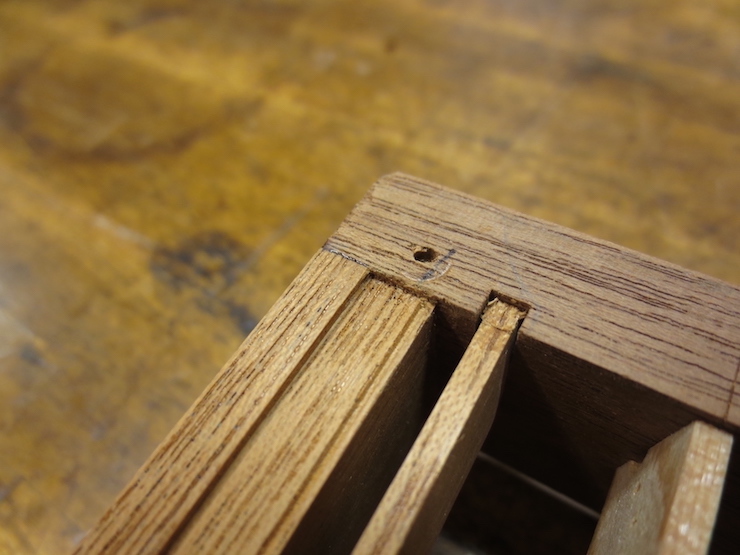
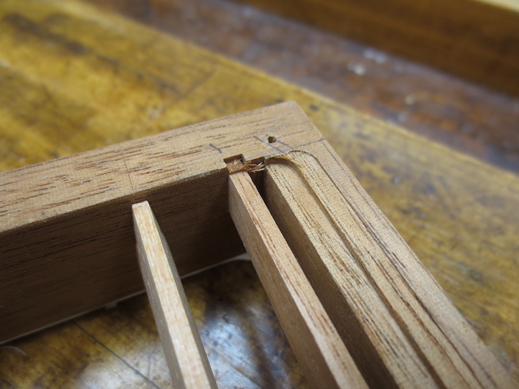
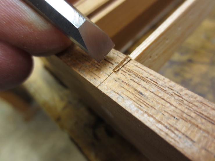
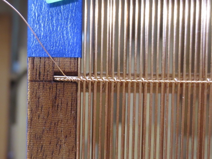
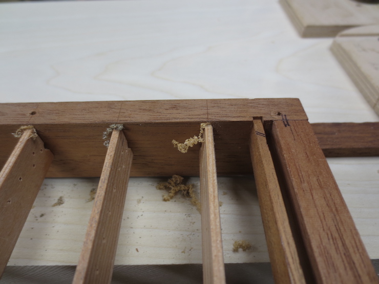
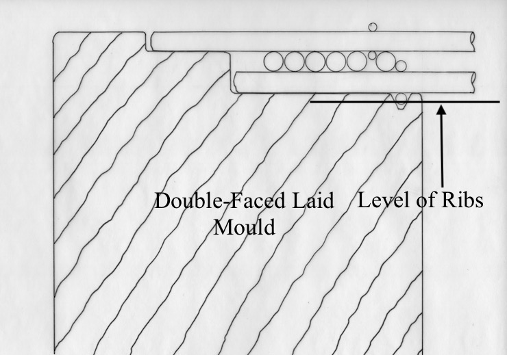
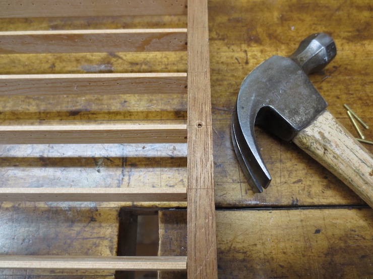
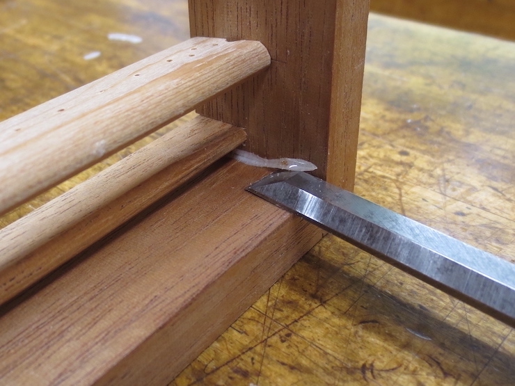
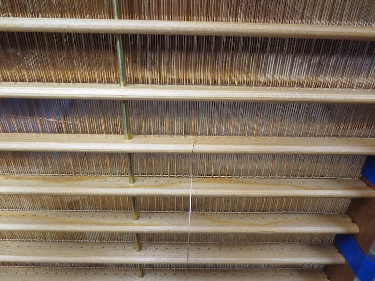
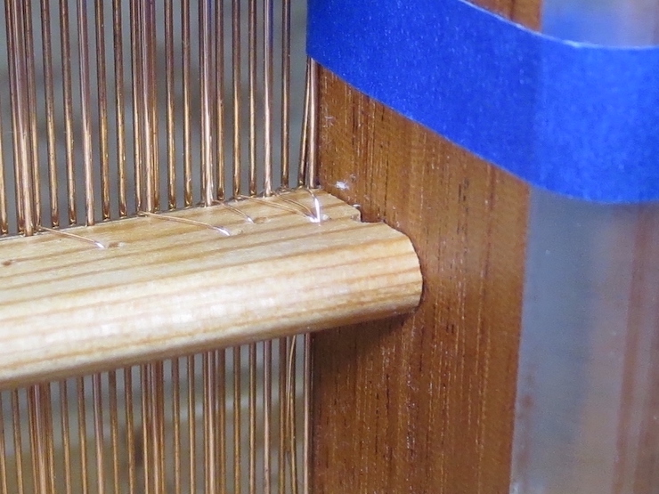
Before sewing a rib the upper chain wire directly above it must be straightened and aligned with the scribed marks at either end.

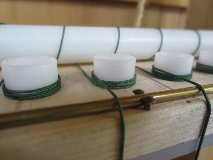
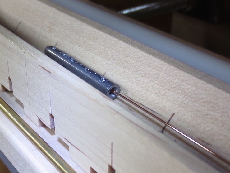
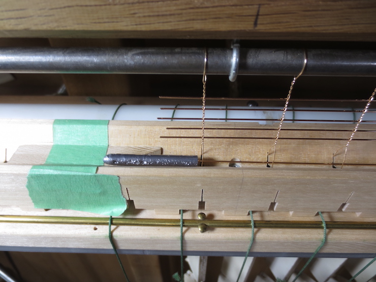
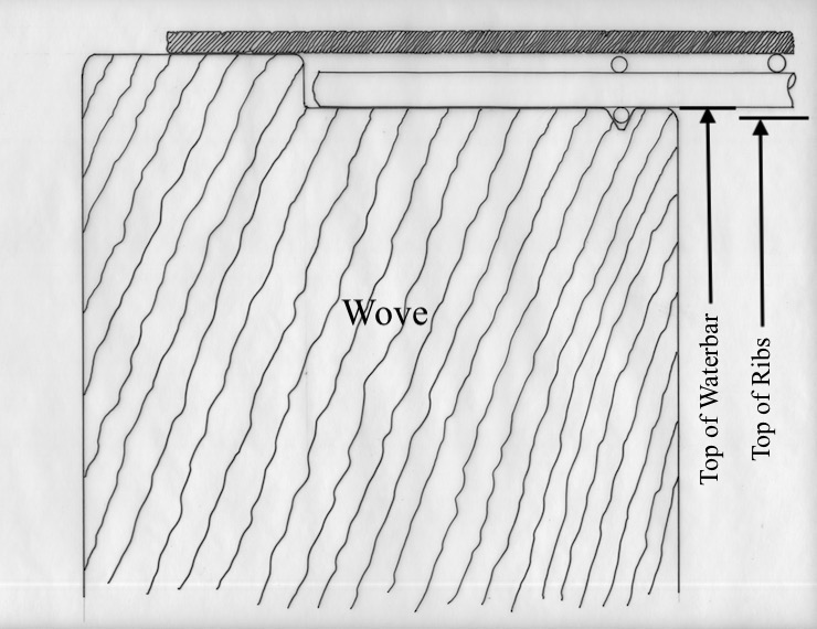
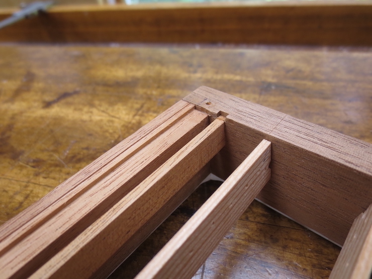
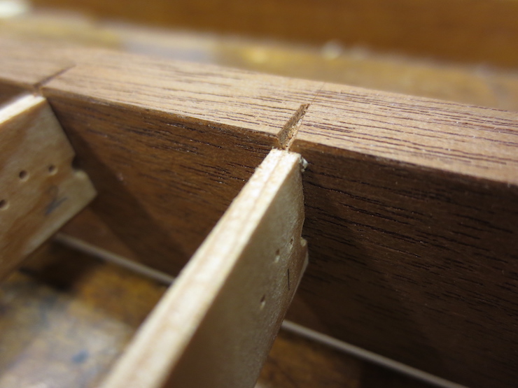
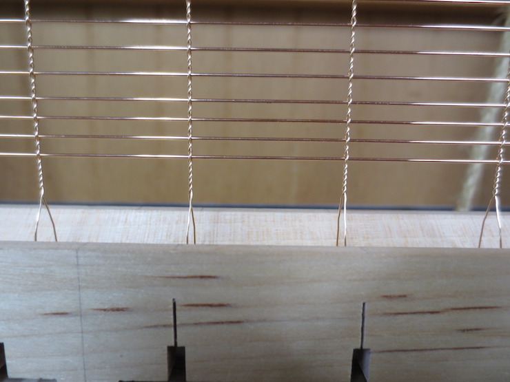
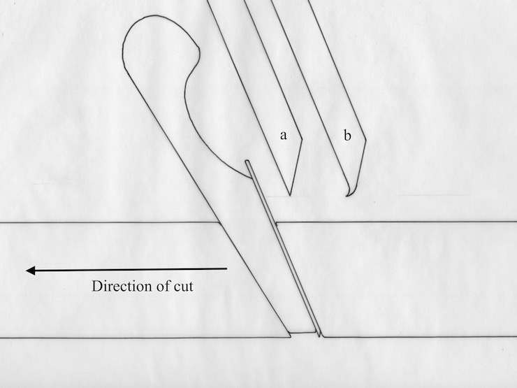
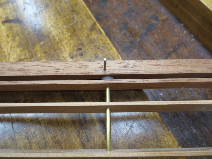
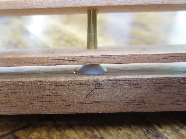
Then the lower chain wire (of the backing) is pulled over to rest directly below the upper chain wire. The straight bridge wire is pushed up against these two chain wires from one side. All line up directly above the narrow flat top of the rib. The wire stitches will hold this cluster of wires in place.

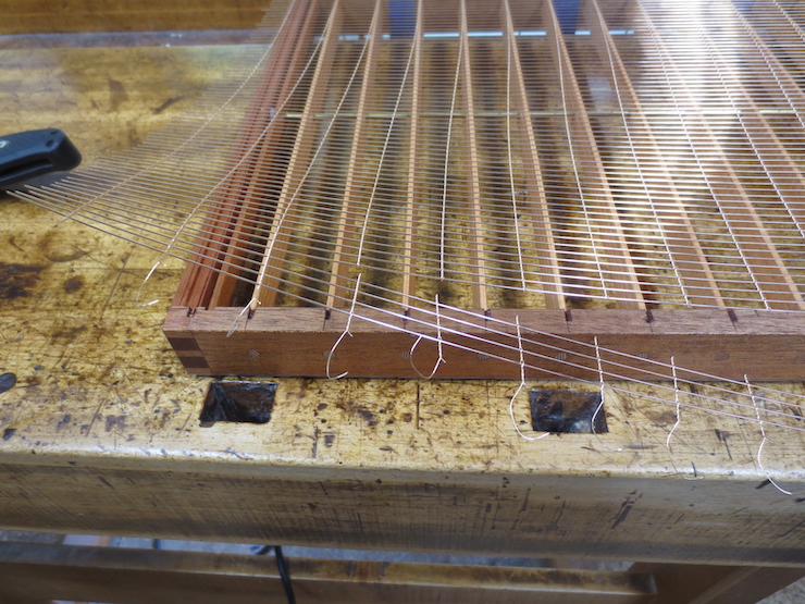
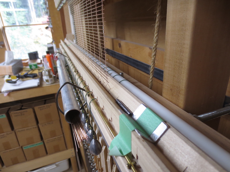
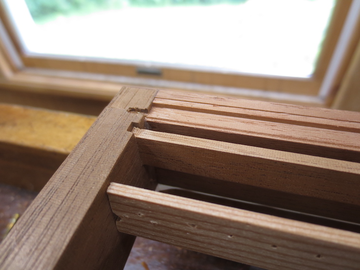
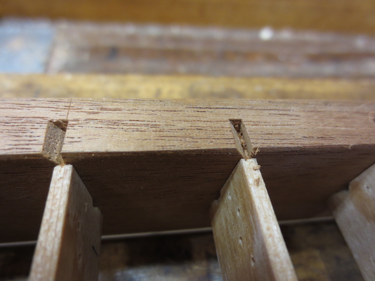
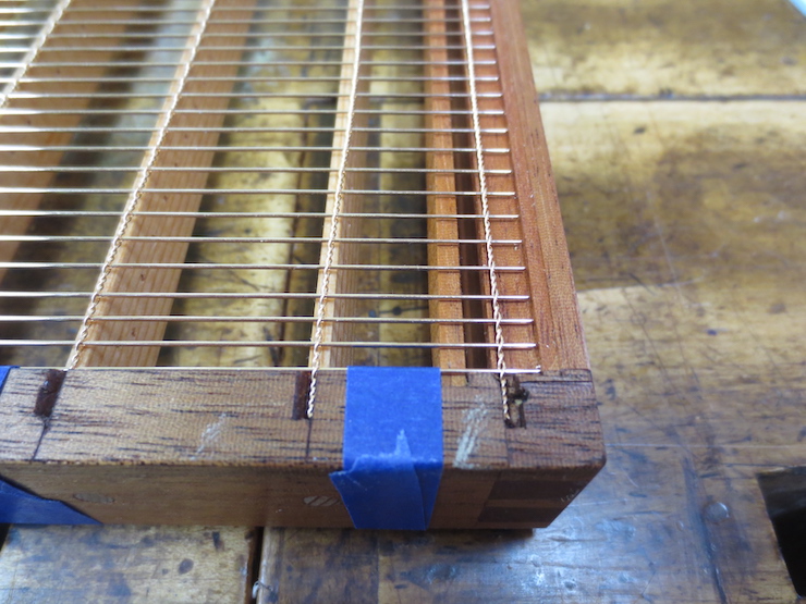
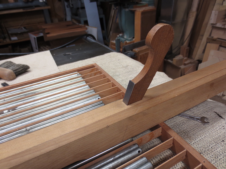
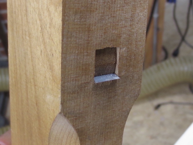
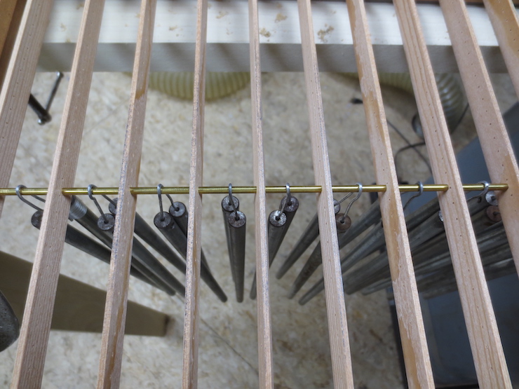
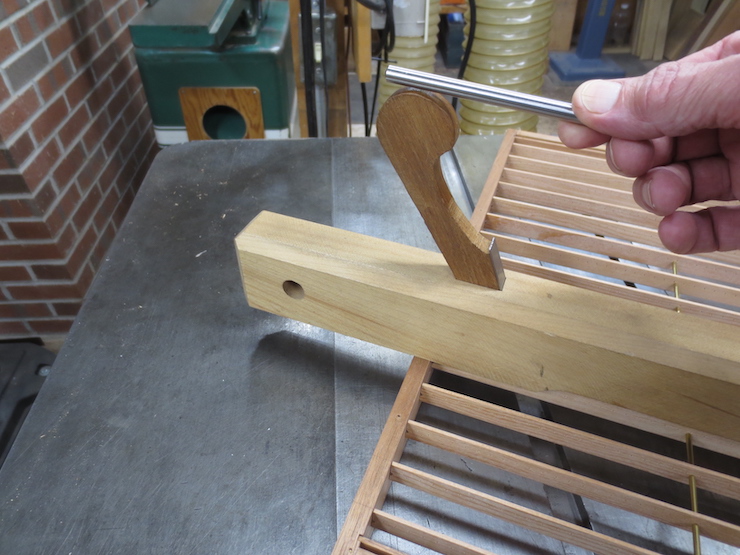
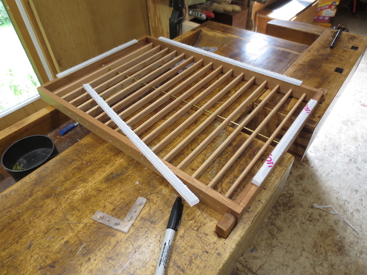
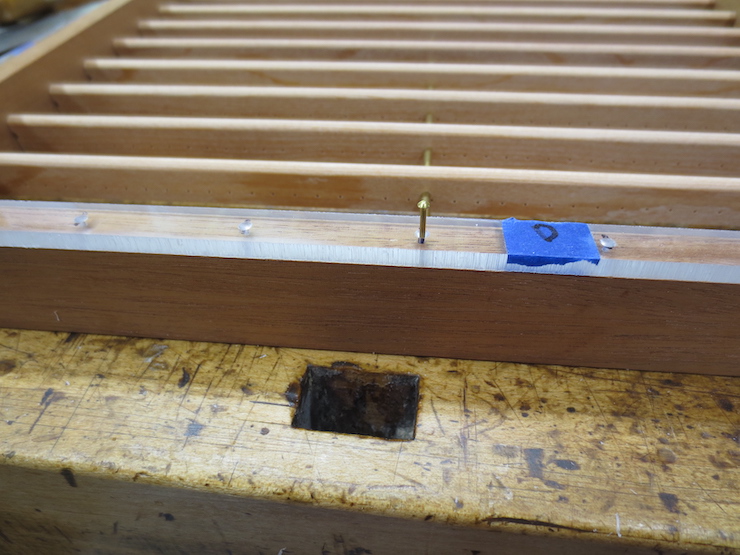
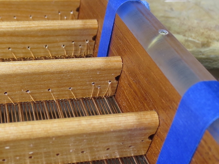
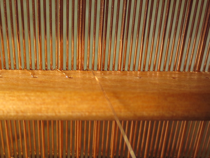
This first rib of this laid mould is ready for sewing. It is one of the middle ribs, the seventh from the bottom. The mould is angled down to allow the holes in the rib to be seen from above so the sewing wire can be fed through them from that direction. Sewing commences from the middle of the rib towards the right hand end. After the right hand side is completed the mould will be tilted up so that the holes can be seen on the other (lower) side of the rib. This is necessary because now the sewing is done from right to left and the wire must enter the holes from the opposite direction.

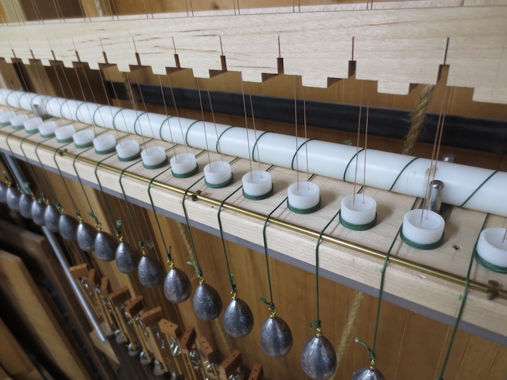
The sewing wire makes a clockwise spiral looking from near to far. Like the thread on a standard screw. (The chain wires are twisted the same way; I wonder if anyone knows what proportion of moulds in history have right-hand twists. ) A sewing wire passes over the chain wire at regular intervals, between laid wires and through the holes in the ribs to stitch the wire parts to the mould frame. The sewing wire should never cross a laid wire; that stitch would ‘stick up’ and leave a light (thin) spot there in every sheet of paper formed.

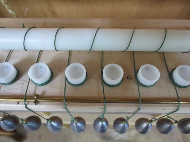
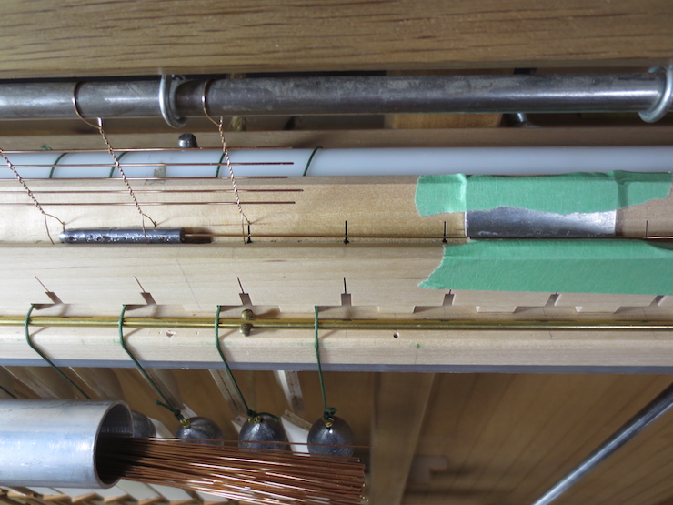
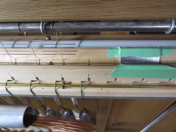
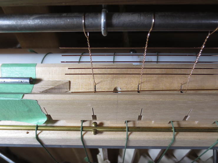
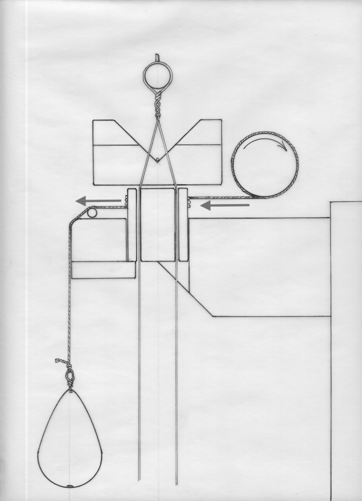
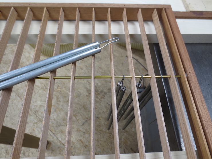
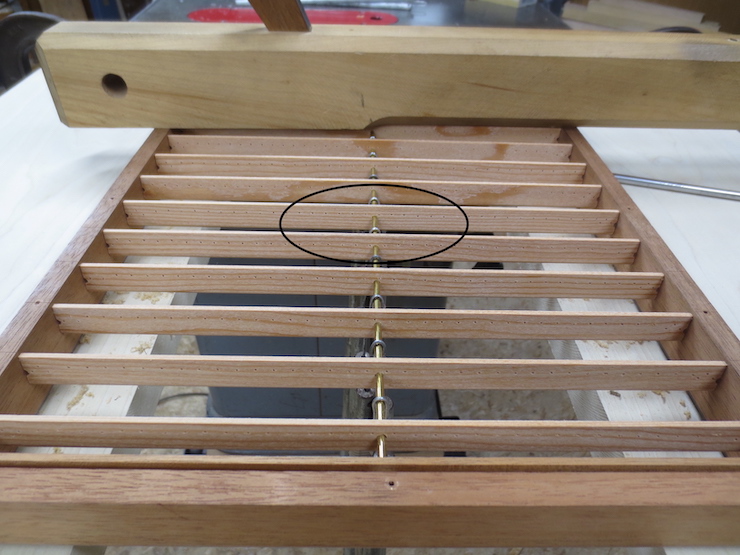
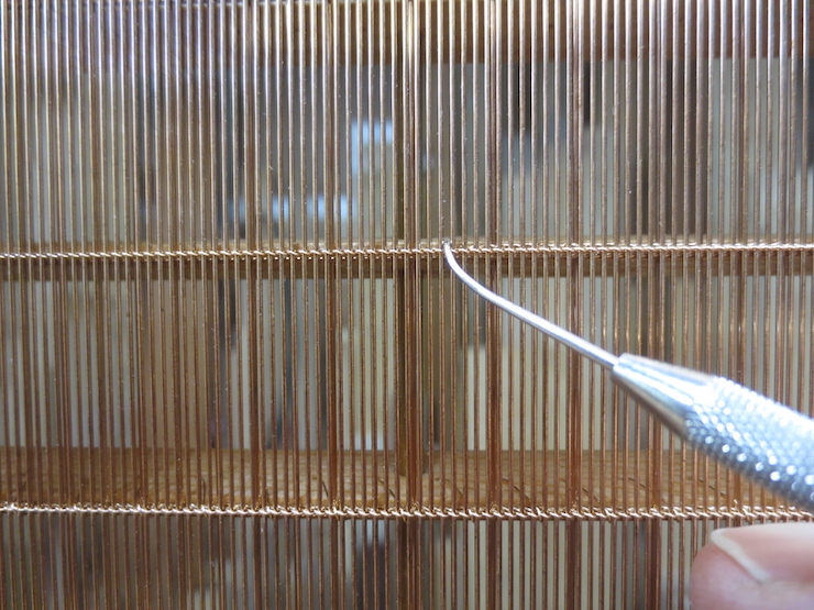
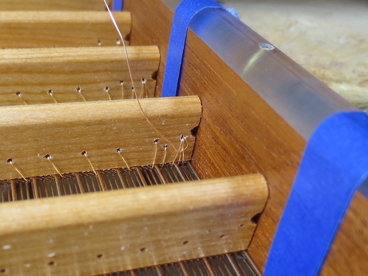
As mentioned each rib is sewn from the center outward. (I am hoping that repetition makes things clearer.) This is the view I have while sewing from left to right. The mould is tilted down so the holes can be seen from above in order to poke the sewing wire through them, one stitch at a time.

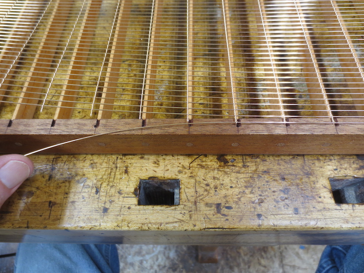
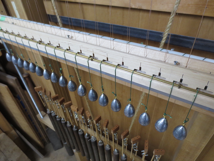
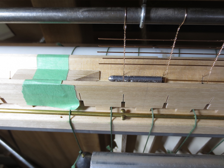
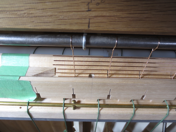
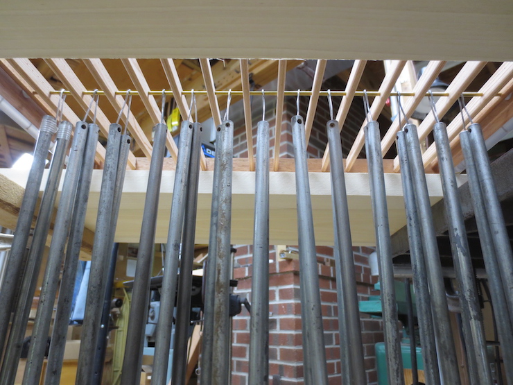
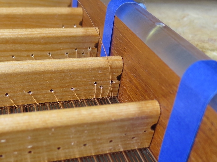
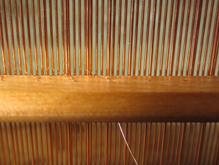
Now the mould is tilted up so that the holes on the lower side of the rib can be seen. The other end of the wire is picked up to finish the rib, this time sewing from right to left.

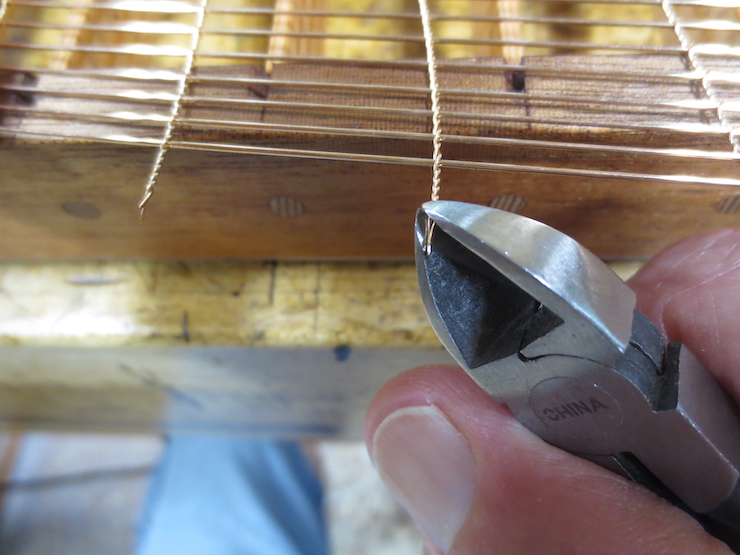
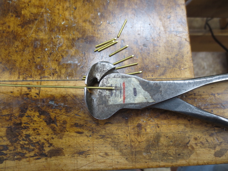
Every stitch is made in several small steps; it isn’t good to drag wire around a corner to accomplish two steps at once. This would flex the wire and ‘working’ it this way will gradually make it harder and more likely to break. (A broken sewing wire must be cut out and re-done.) Instead the wire is handled in such a way that it stays as ‘fresh’ as possible. Kinks must be avoided as they too will stress and weaken the wire if they are allowed to form. If a loop starts to form it can be gently straightened out before it tightens to become a kink. This becomes second nature with time.

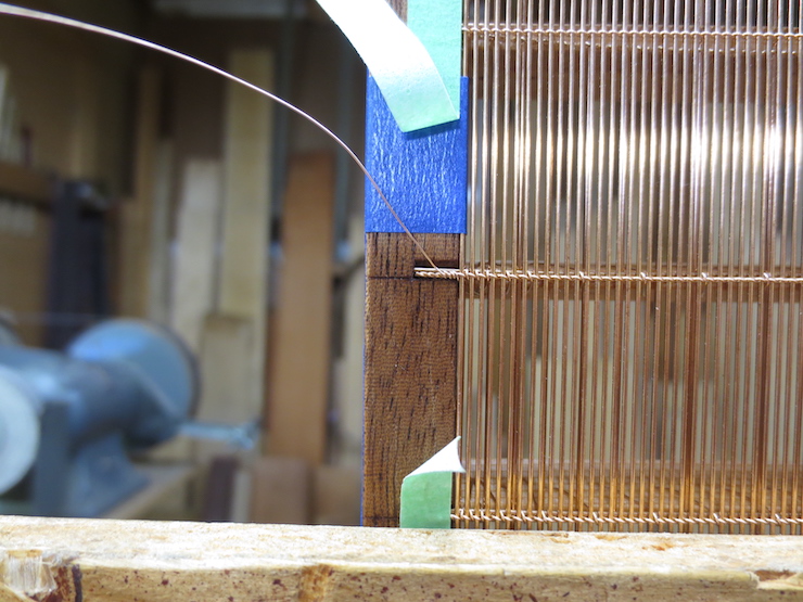
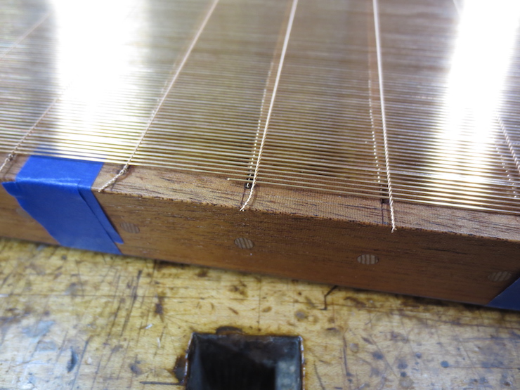
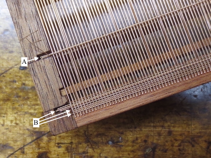
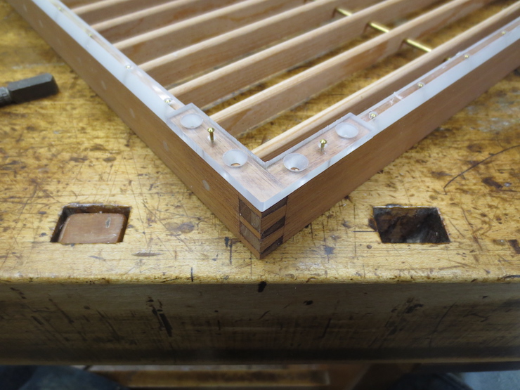
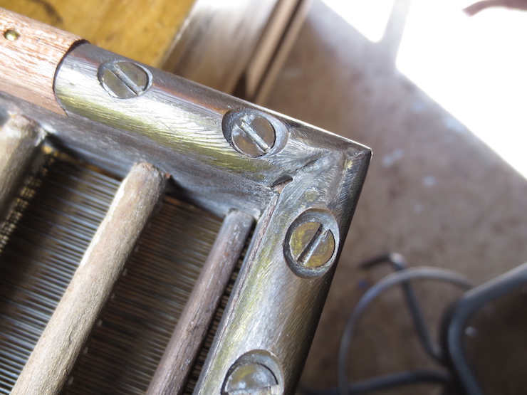
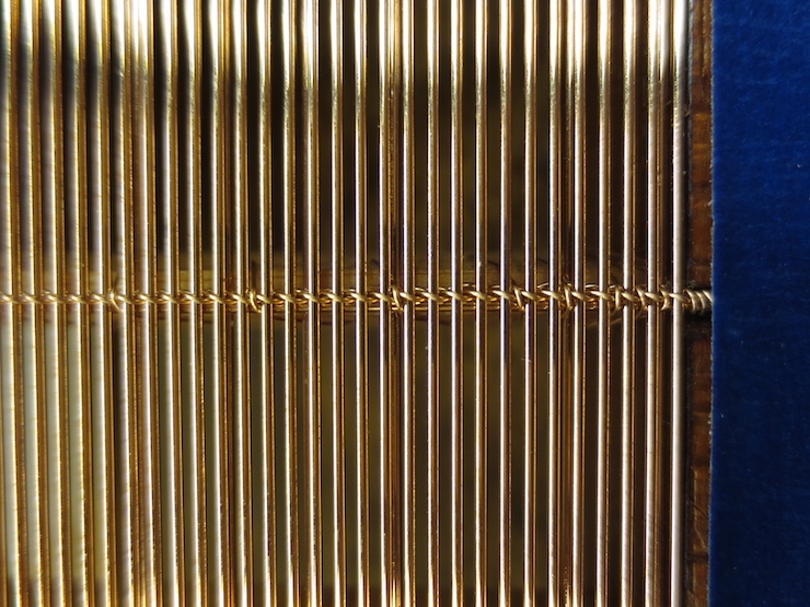
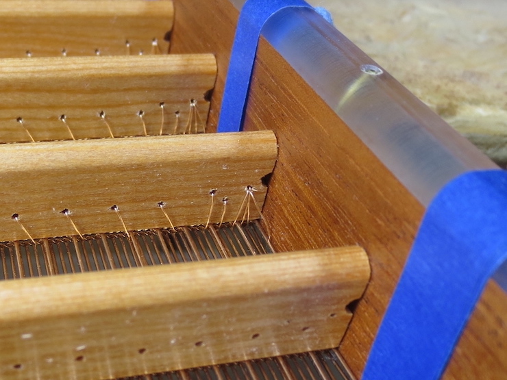
At the end of a rib the stitches are placed in a specific pattern with the last three stitches right next to each other. This pattern is identical for both ends of all the ribs of a mould in order to create a uniform surface for the deckle to press against. A sort of knot is formed (not actually a knot but a way of twisting the wire around itself to hold it in place) and the end of the wire is wrapped two or three times around the twist as seen above. The twist/knot is described in detail below.

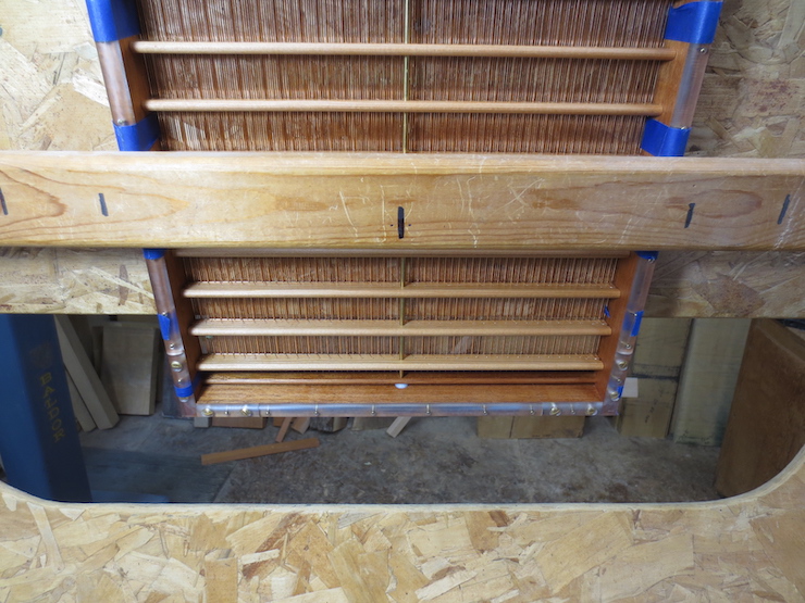
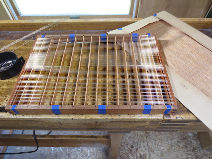
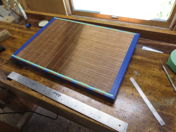
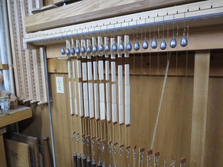
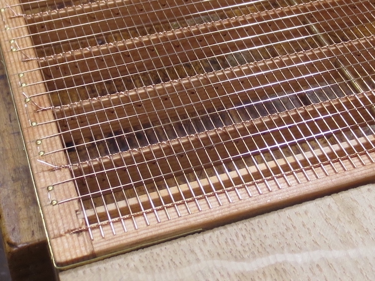
The last rib has been sewn, finishing the first half of this mould. Next the mould will be turned 180 degrees in the frame so the other half can be sewn.

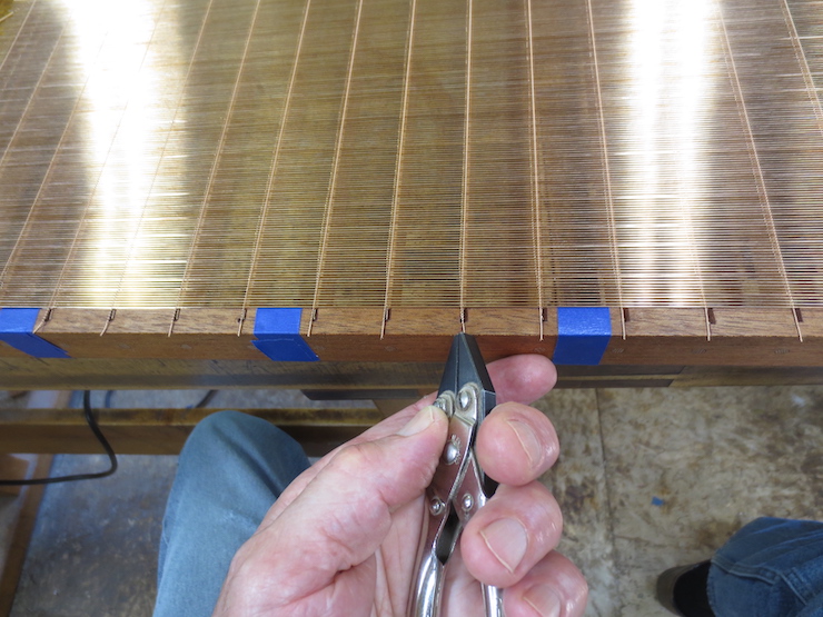
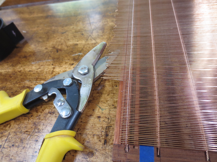
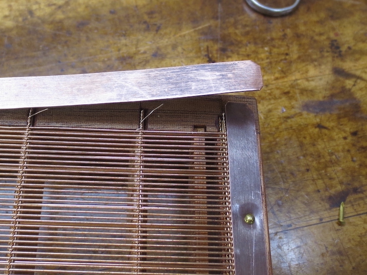
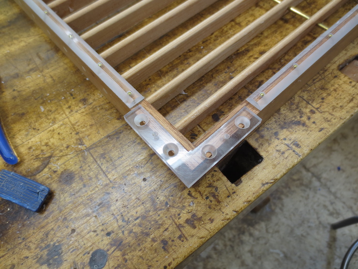
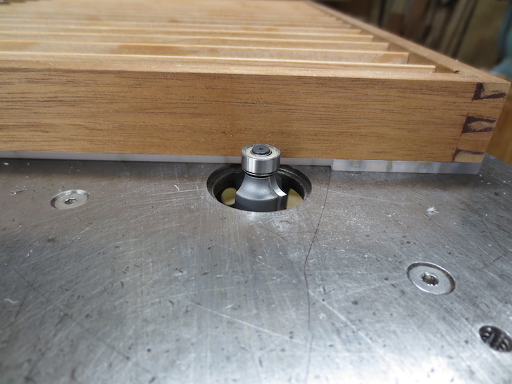
When sewing is completed the tape is removed. To finish the mould copper edge strips will be applied to protect the edges of the wire facing.
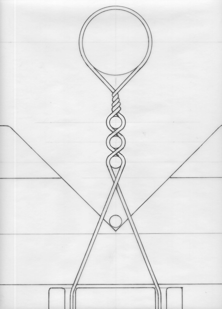

The ‘Knot’

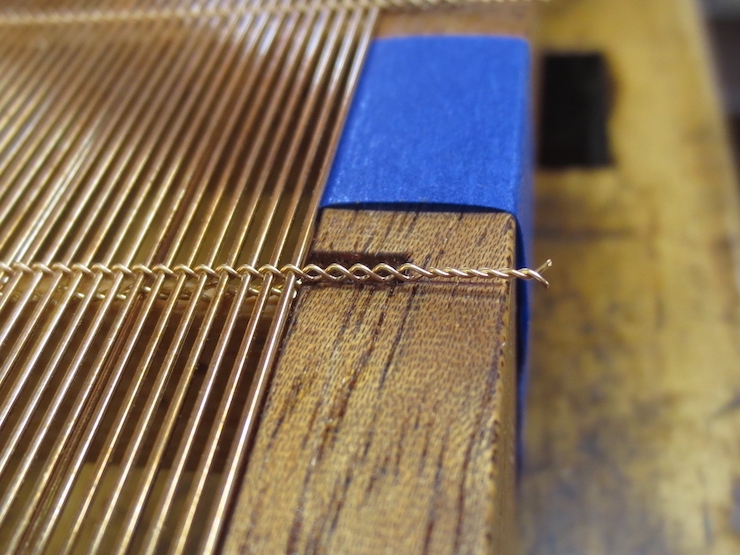
These two sequences attempt to illustrate the steps of forming the twists that secure the sewing wire at the end of a rib. Above, the first stages of the twist/knot.

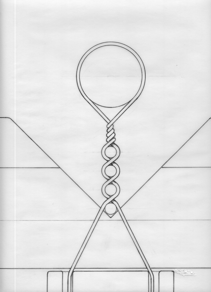
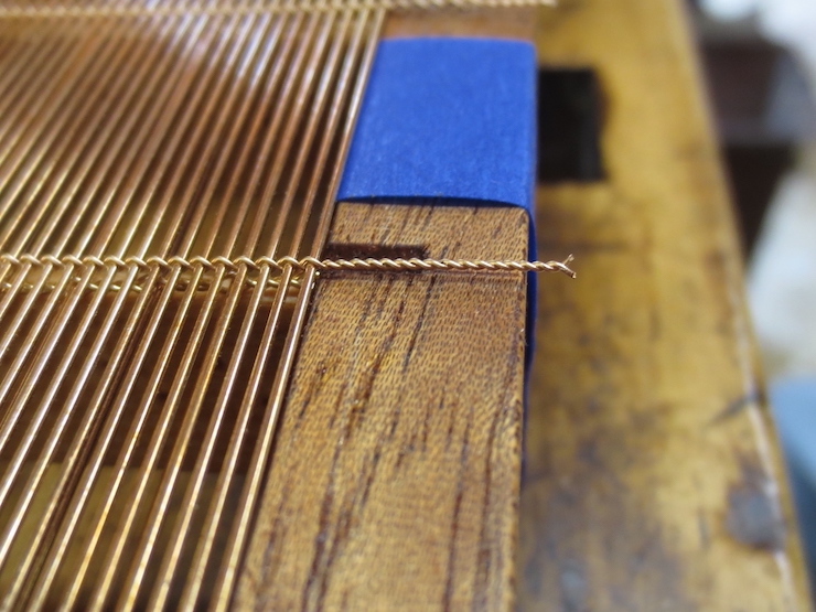
The sequence below shows the steps that take place after the sewing wire passes through the hole to the other side of the rib. Passing the sewing wire under the last stitch and then pulling it tight puts in one more twist (which ends up hidden inside the hole).


The Knot Explained in Stages

After passing over the chain wire the sewing wire is passed through the last hole in the rib in preparation for making the very last stitch. The wire is purposefully left a little loose on this (second to the last) stitch.

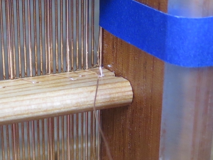
The wire has passed over the chain wire to form the last stitch and is poked up through the loose space that was left.

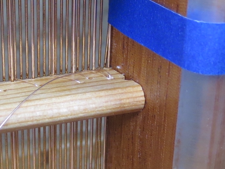
The sewing wire is pulled a little but not too tight; notice that there is still space left under the previous stitch.

The wire has been passed out through the long narrow space between the last two laid wires. This was just so the wire could be aimed up through the aforementioned ‘loose space’ to begin the twist around the previous stitch. (The sewing wire must pass back between these same two laid wires so it doesn’t ‘catch’ one of them.)

The loop is pulled out of the wire. You can see that the wire now twists around the previous stitch. Everything is left a little loose for a purpose….

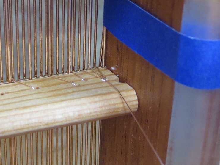
When the sewing wire is pulled tight both parts of the twist are able to distort so they twine more or less equally around each other. This holds the wire in place so it won’t slip back and loosen. (This desireable result is what all the previous fuss was about.) The sewing wire is now fed through the hole one more time and the mould tilted to reveal the other side of the rib. (Next photo.)

Now the wire is passed down between the last stitch and the side of the rib.

Again, it is passed down between laid wires but not pulled too tight.

Now it is passed up between the same two laid wires and up.

When it is pulled tight it puts one more twist around the stitched wire.

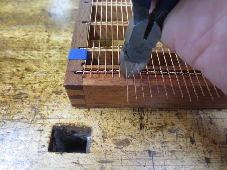
Then the excess wire is fed through the space between the last laid wire and the wooden frame so it can be wound three times around a twist on the top of the mould.


Stages of the Stitches

As mentioned the sewing is done in steps to avoid stressing and weakening the sewing wire. The four photos below show a single stitch being made.

(1) The wire is pulled snug after crossing the chain wire. It is always best when pulling the sewing wire tight to grip it near where the stitch is being formed. Pulling far out on the wire invites kinks and stresses the same parts of the wire over and over.

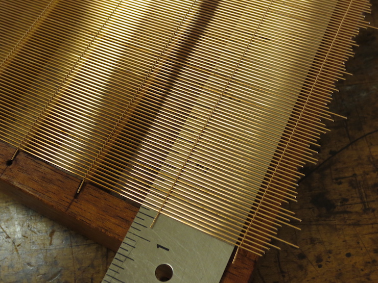
In the early stages a lot of wire must be pulled through every hole in the rib. As sewing progresses the length of the wire diminishes. Even for this small mould there are about 25 holes that the wire must pass through (on each side). If the wire isn’t handled ‘gingerly’ it can be pretty beat up (and weakened) by the time the last stitches need to be made.

(2) The wire is poked into the next hole in the rib and carefully pulled down. After it is in its proper place the wire is gripped near the rib and given a tug to ‘seat’ the wire; compressing the wood around the hole (a little) and locking the stitch in place by forming it around the previous features, the chain wire and the edge of the hole.

(3) Now the wire is poked between a pair of laid wires (below the rib) halfway to the next hole in the rib. The wire is pulled straight out and tugged to ‘seat’ it again. With each step the wire is first gently guided into place and then tugged with a measured amount of force (holding it near the rib) to ‘set’ or ‘seat’ the stitch.

(4) The wire is passed back between the same pair of laid wires above the rib. This way it will cross the chain wire but will not cross a laid wire. Returning to step (1) it will now be pulled straight in (toward the person sewing), gripped near the rib, and given the aforementioned tug to set the stitch. Repeat.

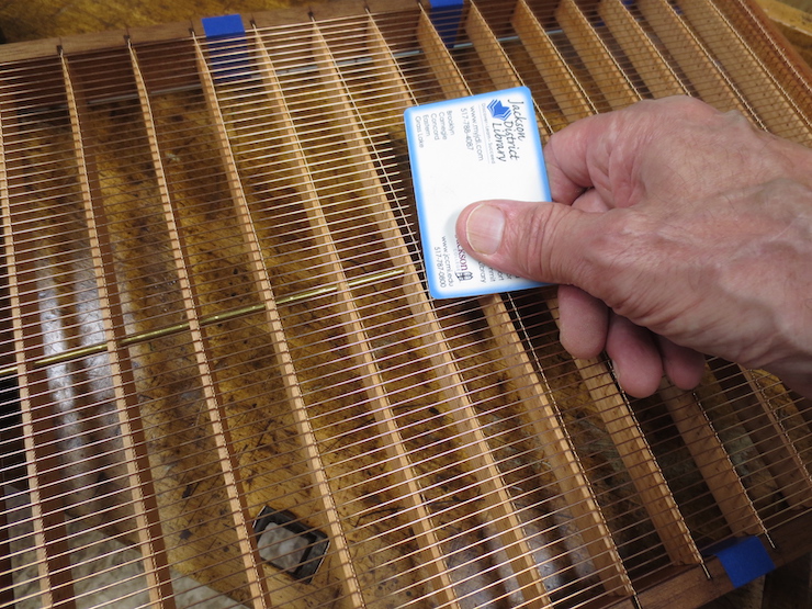
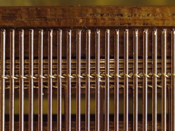
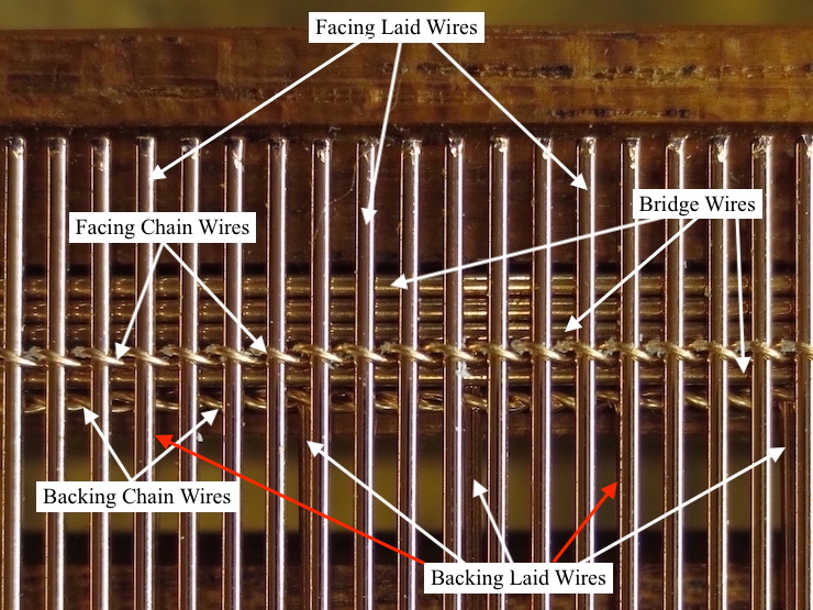
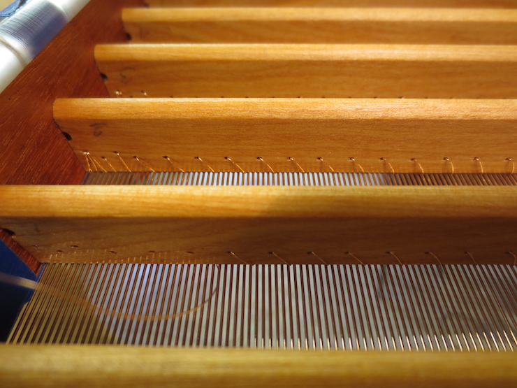
In the photos you can see ‘clumps’ where the backing laid wires interact (visually) with the upper laid wires. This helps you identify the right space to thread the wire through (the same above and below the rib) to avoid crossing a laid wire. Another trick is pulling the sewing wire gently to one side to flex the laid wire sideways to visually indicate the space the sewing wire should pass through on the other side of the rib. It is a good habit while sewing to touch the top of each stitch after it is made (where it crosses the chain wire) to make sure it ‘feels right’ and hasn’t left a ‘bump’ from crossing over a laid wire.

Sewing should not be too tight. In particular a single faced laid mould should not be sewn tightly as the stitches will force the chain wires into the top of the rib (the wood is fairly soft) and the laid facing will bulge noticeably between stitches. The problem will be compounded when the ribs become wet and swell a little.

The main function of sewing is simply to hold the wires securely in place. Each stitch secures a very small area of facing wires; not much force is needed for that. That said, there shouldn’t be too much slack in the sewing wire either. A laid mould MUST be sewn. The chain wires are relatively fragile (and there aren’t many of them) compared to the hundreds of laid wires. They aren’t strong enough to hold the facing together without help from the wire stitches, which evenly distribute the forces that the facing must withstand in use. If the mould were left unsewn, the chain wires would stretch from the weight of all the laid wires, especially during couching (the larger the mould, the worse this would be). A laid wire facing is not strong enough to be attached to the mould only at the edges. It would pull out from under the copper strip and wires would soon begin to bend and break. (On a sewn mould the edges of the wire aren’t really attached along the upper rim of the mould. The twists and laid wire ends are only held in place and protected by the strips of copper but are not themselves fixed to the wood.)


#22 Fitting Backing and Facing to a Double Faced Laid Mould

The mould frame is finished, a backing and a facing have been made for it. Now the parts are fitted together prior to sewing the wires to the ribs.

Fitting the Backing

The twists on one side are trimmed to fit into the notches cut in the frame. The backing has been made wider than needed and with several narrower spaces along one side. Trimming away one, two or three of these spaces (or none) allows the width of the backing web to be adjusted to closely fit the space. If you look closely you can see that the last four wires are closer together than the rest; in this case it worked best to leave three of the narrow spaces along the edge.

The far side of the backing has been taped to the frame and the extra part is being cut off.

One more laid wire needs to be removed.

Now the other side can be taped in place. For now it is only necessary to tape the wire to the mould in every fourth space between ribs.

The chain wire on each end will need to be pushed along the laid wires and re-located. A fingernail will suffice, or an old credit card. It should be moved gradually, with care taken not to bend or stretch the wires.

The laid backing wires are trimmed to fit down into the lowest ledge.

Sometimes the chain wires need to be moved a bit closer to the ribs before putting on the facing.

The backing is fitted and the mould is ready for the facing.


Fitting the Laid Facing

Laid facings also need to be trimmed to fit.

The far side has been taped in place; now some extra laid wires need to be removed to narrow the facing.

You can see that five laid wires were pulled out.

Removing the laid wires has loosened the chain wires so the twists need tightening. These parallel action pliers are useful for this because the mechanism is stiff and they hold onto the wire by themselves after being squeezed. This makes it easy to tighten the twists since you don’t have to squeeze and turn at the same time.

The tightened twists are shortened to fit in the notches.

The laid facing its carefully marked so that it will drop into the shallow ledge after trimming.

Above every rib a bridge wire is fed into the space between facing and backing and alongside the upper and lower chain wires. The bridge wires at the ends of the mould will be added later, after sewing has been completed.

The facing has been taped every fourth space between ribs. More strips of tape are now added to narrow the spacing to every other rib. This way every chain wire is tugged on equally to better align the facing while it is sewn to the ribs.

Overlapping layers of tape are applied over the ends, then a strip of tape is run all the way around the outside of the mould to keep all the other tape from coming loose. (The tape sticks better to itself than to the oiled wood.) The tape prevents the exposed wire ends from being caught and damaged while the mould is being sewn. A narrow strip (green here) protects the twists. It is narrow enough to leave the scribed lines visible along the edges. This helps when adjusting the chain wire to align with these marks.

Preparing a rib for sewing. Starting at a middle rib and working outwards a chain wire cluster will be sewn to each rib with wire. First the upper chain wire is nudged into a straight line aligning with the scribed mark at each end. The lower chain wire and the bridge wire are then coaxed into place (with the tool shown below) to lie right alongside each other on top of the narrow rib. In the photo the middle rib is ready to be sewn. You can see that chain wires on the other two have not yet been aligned.

This dental tool is used to reach down between the laid facing wires to move the backing chain wires and bridge wires into place. It is called a “double ended cowhorn explorer”. It is also used a lot while sewing to help handle the wire.

#21 Making a Backing on the Loom

Another post details the process of making a laid facing. Most of that information also applies to this post so it is worthwhile to review both to gain a fuller picture.

The mould is ready to receive its wire parts. A wire backing fresh off the loom is curvy but will flatten out when taped to the mould. This post will show how the backing was made.

The counting wheel of the loom must be changed from 8 pins (previously used for the laid facing) to 4 pins to make my standard laid backing. On this loom 4 pins and 9 ‘clicks’ yields a spacing of 5.78 wires per inch. (‘Clicks’ refers to the sound the pawl makes as it drops off pins as the wheel is turned.) The twin lead screws of this loom are fixed at 13 threads per inch but the number of pins and the number of clicks can be changed to produce a number of different laid facings and backings. A simple formula calculates the wire spacing: Pins x thread (fixed at 13) / clicks = wires per inch. (In this case: 4 x 13 =52 then 52/9 =5.78. ) The laid facing made with the 8 pin counting wheel used 5 clicks to make 20.8 wires per inch. (8 x 13 = 104 then 104/5 = 20.8.)

This is about the heaviest wire that is useful for making chain wires. It is .015″ diameter soft phosphor bronze and makes the chain wires for this laid backing. Wove backing uses a .013″ diameter wire for a narrower space between laid wires. Laid facings can use almost any size chain wire between .012″ and .008″ diameter.

These spindles have recesses on one end and can be oriented in two ways. Using them with the recesses on top narrows the angle at which the wires are twisted for more widely spaced backing wire. Turning them over flat side up widens the angle for the tightest twist, more useful for laid facings.

As many spindles as needed are put in the holes in the spindle rack. Then they are wrapped with the weighted cords that drive them to twist the wires.

The spindle holes will need aligning after all are connected to drive weights.

After all spindles are rigged with cords and weights they are aligned by turning them clockwise. They can’t be turned backwards; the cords tighten and prevent turning counter-clockwise.

The spindles are ready and the wire trough is placed above them. For now it is elevated on posts to make it easy to string up the loom with the chain wires. Lined up along the wire trough are ‘wire slides’, one for each pair of chain wires. They are used along with wire spacers to keep the wire from twisting below the spindles.

Lengths of wire have been draped over a bar at the top to form pairs. The two ends of each wire pass through a cross-wise slot in the wire trough, down through holes in the spindles, through holes in the wire slides and are twisted tightly together at the bottom. Then a one pound weight is hung on the wire slide at the end of each pair to hold the wires taut.

The posts have been removed and the trough lowered over the spindles. You can see three of the five screws that will be tightened to hold it in place.

Wire spacers are installed below the twisting mechanism and above the wire slides. They are pieces of foam board with narrow slots cut in the sides for the wires to rest in.

The laid wires are hand straightened and slightly curved so they need the help of this wire guide to slide through the row of upside down “Y” shaped openings in the wires. The wire guide is made of lead to be as heavy as possible for its small size. The guide is pushed along by the laid wire and removed after reaching the end. You can see this in the slide show sequence below.

This shows how the wire guide is employed. Halfway through the the sequence the view switches to the left to show how the guide is removed. After this step the backing is lowered onto the newly inserted laid wire (by releasing the treadle) and the chain wires are given three half-twists to bind it in place. The twisting mechanism is then lowered the prescribed distance (9 clicks), the treadle lifts the backing and the sequence repeats. Each time another laid wire is added the backing grows wider.

This sequence of photos shows how the twisting mechanism moves down as the web of wires grows wider. Notice how the (white) wire spacers slide down the wires and that a row of them is removed periodically.

Some of the parts of the loom are labeled here. The wire lifting beam lifts about 1/2″ when the treadle is stepped on. This lifts the chain wires so a new laid wire can be slid down the trough between their splayed ends. With this loom different spindle rack/wire trough sets must be substituted to change the chain wire spacing. The narrowest spacing possible for this loom is 13/16″ on center.

These chain wires are 1-1/8″ apart here and match the rib spacing of the mould.

The aluminum angle taped in place helps guide each laid wire into the small hole in the end of the wire guide.

The first step of fitting the backing.


More Information about the Loom

This drawing shows a cross section through a spindle, wire rack and wire trough. When the twisting crank is turned (in the direction shown by the curved arrow) the cord is reeled in and the spindle is turned. When the cord is pulled to the right it is tightened from two directions (as shown by the two straight arrows) so it cinches down on the spindle and turns it. This twists the pair of chain wires 1/2 turn.

After a laid wire is added by twisting the chain wires the whole ‘web’ is lifted by the treadle (not shown). This engages the untwisted parts of the chain wires in the cross-wise slots in the wire trough. This prevents the spindles from turning backwards when the weighted cords are released by reversing the twisting crank. The cords slip on the surfaces of the spindles since the cord is only pulled from one direction (the weighted end). The spindles re-align themselves each time the cords are released.

In this cross section drawing the web is lifted and a laid wire has been slid into place beneath the twists.

The foot treadle is released and the web is lowered down onto the laid wire.

The chain wires are all given a half twist, adding one new laid wire to the facing. If a backing were being made the twisting sequence would be repeated two more times before adding another laid wire to the web. The web must be lifted each time since the mechanism allows only one half turn of the spindles at a time.


Logically the next post in this sequence would be “Making Laid Facings” but it will be skipped because it was posted previously and can be easily referred to.

#17 Finishing the Mould Frame

This post covers the remaining steps needed to prepare a double faced laid mould to receive its wire facing and backing. The topic of ledges and how they relate to backing wires in wove and laid moulds seems to need some explanation. It is important to understand the purpose of these structures so this post contains some additional information not directly concerned with actually ‘doing the work’.


Backing wire and the need for Ledges

Ledges aren’t essential for the single-faced laid mould, the oldest and simplest European style paper mould. I’d guess that many single faced laid paper moulds have been made without them, with the tops of ribs and mould frame made to form an unbroken flat surface. When covered with a laid facing the results can be pretty good.

But for double-faced moulds, laid or wove, this doesn’t work. In order for the upper layer of wire to be supported at the sides and the ends of the mould the lower layer of wire (backing) needs to be set down into the frame.

The solution is to lower the ribs and create recessed ledges at the ends of the mould. The ribs and ledges together support the wires of the backing so that it, in turn can support the wires of the uppermost layer, the wove or laid facing, at the proper level. The ledges have a second, perhaps incidental function. This is to trap the ends of laid wires to arrest their tendency to work out of the ends of the mould. This is the reason that I use ledges for single faced moulds even though they aren’t essential.

This represents a cross section through one end of a single faced laid mould; this part of the frame lies parallel to the ribs and perpendicular to the laid wires. A simple ledge is shown, as deep as the diameter of the laid wires resting in it. The drawing also indicates the level to which the waterbars (not shown but just off to the right) will be trimmed. Their tops should be at the same level as the ledge because the laid wires should rest on both. The tops of the ribs (which would be farther off to the right) form a plane at a slightly lower level. This is to account for the thickness of the chain wires of the laid facing. Copper edging that will be added to protect the wire ends and bind them to the top of the frame is not shown in these drawings.

The simple ledge of a single-faced laid mould. The waterbar has been leveled at the same time as the ledge was created. The ledge is recessed by the diameter of the laid wires so their top surface ends up even with the top of the wooden frame.

A double-faced laid mould needs a deeper ledge. Making it in the form of two steps avoids weakening the mould frame along the outer edge. Backing laid wires rest on the lower level. These, along with bridge wires, provide a firm base for the laid facing. The narrow groove along the inner edge of the deeper ledge traps the un-sewn ‘loose’ chain wire at each end of the mould so it can’t shift sideways along the laid wires.

The more complicated ledge of a double-faced laid mould. The upper laid wires should be even with the top of the wooden frame so the backing wires must be set lower to make this possible.

This shows the various wires of a double faced laid mould and how they are situated in the ledge.

One does not need to be so fussy when fitting wires to a wove mould but the backing still needs to be recessed to support the wire mesh level with the wooden frame.

The ledge of a wove mould is similar to that of a single-faced laid. It is a little deeper and the margin at the outside edge is wider.


Creating the ledges and leveling the waterbars.

The ledge is created using a router table which in my shop is the wing of a tablesaw modified to allow a router to be mounted beneath.

The dial indicator was used to set the router bit to make the cut as deep as the thickness of the layer or layers of wire.

The waterbar has also been routed to the same level as the lower ledge. The table saw fence must be adjusted for the bit to reach over to the waterbar.

Straight from the router…

.. and with corners cleaned up with a chisel.


Making the Trap Groove

This pointed router bit is used to make the trap groove.

The trap groove has been routed and a notch has been chiseled, extending the bottom of the groove and making room for the ends of the chain and bridge wires.


A few more details

I route out a little area at the corners where adjoining pieces of copper strip will overlap. It is the same depth as the thickness of one strip (.015″) and will keep the strips from bulging up at the corners where there will be two layers.

The edges of the mould frame are eased off with a plane and lightly sanded.


Notches for the Twists

Laid wires will reach only to the inner edge of the mould frame but the twists must lap over it. This single-faced laid mould needs very small notches for the twists..

They are a little deeper for the backing wire twists of a wove mould.

Notches for a double faced laid mould are a different story. A bundle of wires will need to fit in each notch so it must be roomy. Each notch will accommodate the ends of the upper chain wire twist, a bridge wire, and the lower backing wire twist. If these wires are too crowded the springy bridge wire will veer off to the side making it impossible for the chain wires to lie straight on the rib.

A double-faced laid mould frame with notches completed.


Applying Finish

I’ve been using Watco oil as a finish. It dries a little more predictably than boiled linseed oil and makes the new mould look nice. Either is fine; both will wear off before too long! It is pointless to try to waterproof the wood of a paper mould. Water will inevitably get into the wood and a surface coating like urethane varnish will eventually start flaking off. I believe that untreated wood is better for forming sheets. Water flows more evenly along wet wood than over a shiny, hard surface. Wood is hydrophilic and attracts water. Water is attracted to wet surfaces and can flow smoothly there. A varnished surface is hydrophobic and repels water so water beads up and flows unevenly.

When the finish dries the mould will be ready to receive its wire facing.


#18 Definitions of some Unfamiliar Terms

Defining some terms may make these posts easier to understand. I have chosen some words when a traditional term was not known to me. The terms are in italics; accompanying text and photos are intended to define and explain their meaning.


~frame sides: The two longer parts of the mould frame parallel to the laid wires. Ribs are set perpendicular to the sides, both ends being fixed in holes drilled there.

~frame ends: The two shorter parts of the mould frame parallel to the ribs.

(above) The underside of a wove mould. This photo identifies the frame sides and frame ends along with a few other parts of a paper mould.


~chain wire / chain wires: These words are especially confusing to use. I will use the singular “chain wire” in these posts to mean a single pair of wires that spiral around each other, binding laid wires side by side to make a facing. Visually it appears as a single line of wire, resembling a miniature chain, crossing the laid wires at a right angle. I will use the plural “chain wires” to refer to more than one of these structures. Examples of the two uses might include: “Each rib has a chain wire positioned above it.” And “All of the ribs have chain wires positioned above them.” (It is awkward to write many times about “chain wire pairs”. And what is the plural of “chain wire pairs”?)

(above) An excerpt from a drawing showing the process of making a laid facing in a loom. It provides a simplified view of the structure of a laid facing including a few laid wires, a chain wire and a twist.


~laid facing: The uppermost wires of a laid mould. The porous wire surface on which macerated cellulose fibers are collected when forming sheets of paper.

(above) This photo shows a laid facing being fitted to make a ‘single faced laid’ mould. This is the simplest and oldest type of European style paper mould. Another type of mould, ‘double faced laid’, uses this same type of facing supported upon an additional layer of wires, called ‘backing’.


~wove facing: The uppermost wires of a wove mould. These are in the form of a fine screen of woven wire that collects fibers to make a sheet of wove paper.

(above) A wove facing is being trimmed and fitted to its mould. A wove mould always has two layers of wire and is sewn in two stages.


~backing: A layer of wires that lies beneath a laid or wove facing to support it from below. Backing is prepared on a loom like a laid facing but with wires spaced much further apart.

(above) Backing being fitted to what will become a double faced laid mould.

(below) The very bottom of a large backing that is finished and ready to cut off of the loom. Three half-twists in the chain wires keep the laid wires widely spaced. The last four laid wires are more closely spaced with two half-twists in the chain wires. Including a few narrow spaces along one edge makes it easier to fit the backing to the mould frame.


~facing laid wires: The long, straight wires that make up a laid facing. There are hundreds of laid wires lying close together in a typical laid facing. They are fastened together by a dozen or so widely spaced chain wires.

~backing laid wires: The long, straight wires that make up a backing; these wires are the same as facing laid wires but spaced further apart with extra twists between them.

(above) Facing laid wires and backing laid wires are shown in this extreme close-up. The red arrows show where two backing laid wires are hidden under laid wires of the facing.


~loose chain wires vs. sewn chain wires: With the exception of one chain wire at each end all of the chain wires of a mould are fastened in place, each being sewn to a rib. The two ‘loose’ chain wires at the ends can’t be sewn to a rib. To secure them they are ‘trapped’, either in a groove in the wooden frame (single faced laid and wove) or between two bridge wires (double faced laid).

(above) The chain wire running across the top of this double faced laid mould is loose (not sewn), but it is trapped between bridge wires to keep it from wandering. The chain wire seen along the bottom of the photo is sewn to its rib.

~bridge wires: Bridge wires are physically the same as laid wires but have a different purpose and are used only in double faced laid moulds. They are straight, stiff wires that bridge the widely spaced backing laid wires to provide a smooth, firm support for the laid facing. Over each rib, a single bridge wire runs alongside and between the two chain wires (one facing, one backing) and is sewn in place as part of a bundle of wires. Bridge wires are also used at both ends of a double faced laid mould to provide extra support for the ends of the facing laid wires. They provide a firm base for the laid wires which keeps them from distorting badly when copper edge strips are tacked in place.

(above) Above each rib a single bridge wire is inserted alongside chain wires and between the laid wires of the facing and backing. It crosses the widely spaced laid wires of the backing, providing a smooth, solid support for the upper facing to prevent it from being cinched down unevenly by the stitches that bind it to the rib.

(below). You can see both uses for bridge wires here; at “A” as one piece of the bundle of wires sewn to a rib, and at “B” lined up in a group to support the ends of laid wires where they lap over the frame end.


twists: These are extensions of the chain wires that lap over the frame sides.

(above) Extra laid wires have been pulled out to fit a laid facing to its mould leaving this twist a bit loose.

(below) The same twist has been tightened and will be trimmed to fit in the notch. After the mould is sewn all of the twists will be covered by copper edge strips to protect them.


single faced laid: The most basic type of paper mould having a single layer of laid wires sewn directly to the ribs. Until the mid 18th century it was the only type of European style mould. Paper made on this type of mould is distinctive for having ‘shadow zones’ along the chain wires. This is a result of the rate of drainage along the ribs differing from the rate of drainage between the ribs.

(above) It is easy to see that there is only one layer of laid wires in this single faced laid mould. A laid facing is in the process of being sewn to the ribs.


double faced laid: A type of laid mould developed around the middle of the 18th century having two layers of wire. Adding the extra layer (backing) improves drainage and eliminates the uneven formation typical with single faced laid.

(above) Two layers of wire are visible here, identifying this as a double faced laid mould.


wove: Wove moulds were also devised around the middle of the 18th century. Paper made on these moulds lacks the distinctive laid pattern because the facing is a nearly featureless fine woven mesh. Wove moulds require a backing; the wires of the backing keep the relatively soft wire mesh from sagging between ribs.

(above) A wove mould with deckle in place. The support grid of the backing can be seen through the fine wire mesh of the wove facing.


wove backing: The layer of wires devised to support the facing of a wove mould. It resembles a laid facing but with laid wires spaced much further apart.

grid wires: A grid is created on top of the backing to support the wove facing evenly. The grid is made of a single wire strung back and forth between small brass or copper nails. Two rows of stitching between each pair of ribs will secure the facing to the backing.

(above) The wove backing has been completely sewn to the ribs and a grid has been created to provide an even support to which the wove facing will be stitched.


ledge: A shelf or lower level created to support laid wires where they overlap each end of the mould frame. The cut ends of the wires must be protected by a copper strip. It is difficult to keep this strip from distorting the wires when it is tacked down. This can be minimized with careful attention; aiming to support the laid wires at the same level as they are supported by the ribs.

(above) One end of a double faced laid mould with two ledges. The deeper one supports the ends of the backing laid wires. The shallow ledge supports the ends of the facing laid wires.


trap groove: A groove cut along the inner edge of a ledge to trap the loose, un-sewn chain wire so it can’t move.


copper edge strip: The narrow strip that is affixed to the top edges of the frame to protect the vulnerable ends of laid wires and twists. Along the ends it also functions to bind the laid wire ends to the mould; holding them in place to align them evenly with the rest of the facing.

(above) A copper strip has been tacked to both ends of this mould. It protects the ragged ends of the laid wires while holding the ‘loose’ chain wires (facing and backing) and bridge wires in place. The strips along the sides do less; serving only to protect the twists. If not covered the ends of wire are vulnerable and likely to be snagged and bent. In moulds receiving hard use chain wire twists sometimes escape from their covering and will be bent, first one way, then another. They eventually fatigue and break, most likely right at the first laid wire. The chain wire will loosen near the break and laid wires may come loose, too. The copper strips at the ends sometimes work loose, allowing laid wires to protrude and become damaged.

#16 Leveling the Ribs

The wooden structure of the mould is complete; now the tops of the ribs are scraped level in preparation for sewing down the wire facing.

I like to pre-load the mould with weights before leveling the ribs. This gives the mould a very subtle camber; an extremely shallow arch in all directions. The forces of forming sheets and couching push against the ribs. By its nature a mould is weaker and less well supported in the middle. Leveling a mould under weights gives this part a little lift to compensate. It is surely better for the top of a mould to be slightly domed than either flat or hollow.

The photos above and below show one way to support the long sides of the mould while allowing weights to be hung on the single brace rod that supports the ribs.

I cobbled together this structure by clamping some planks to my table saw. I will likely try to come up with something more convenient in the future.

This method of hanging the weights is fairly new to me; earlier on two brace rods and deeper ribs allowed the 12″ x 3/8″ diameter steel weights to be simply laid in place between the ribs. As shown below, a mould could be placed on any flat surface while leveling the ribs. The smaller mould shown above uses 5/8″ ribs and there isn’t enough space above the brace rod for the weights (even if there were two brace rods). The weights must be hung from the single brace rod to pull down on the ribs.

This larger mould had 3/4″ deep ribs and two brace rods passing through the ribs. Two rods allowed the weights to lie horizontally between the ribs and below the surfaces to be scraped.

The weights are hung in pairs from the single brace rod. These are leftovers from an unrelated project. Some have set screws which make it easy to attach the wires. A simple hole or even tape would also work.

Here’s what they look like from below. The two weights on the left have been attached to the wire with strapping tape.

The blade for this scraper plane is a narrow strip hacksawed from a woodworker’s card scraper, sometimes called a cabinet scraper. The arrow shows the direction that the plane is pushed. It may seem backwards when looking at the angle of the blade. This is because a sharp, forward facing burr has been formed on the backwards facing blade.

A cross-section drawing of the scraper plane and enlarged views of the blade. The burr at ‘b’ is much exaggerated and the blade shown wedged in the plane would normally be set a little lower.

The long wooden body of the plane rides on top of the long sides of the mould frame. The blade is advanced by small increments for as many passes as it takes to completely level all of the ribs.

The scraper blade needs to stick out quite a lot to reach the ribs that are recessed below the top of the mould frame.

The scraper is ground and honed at about 45 degrees. Then a ‘burr’ or ‘hook’ is turned on the sharp edge with a burnisher. You can see the burr in this photo. This allows a scraping action which is safer than the cutting action of a normal plane.

The iron or blade of a woodworking plane protrudes from a narrow mouth in the sole, the flat bottom surface of the tool. The sole normally rests on the wood right next to the blade and keeps slivers of wood from rising up when caught by the sharp edge, particularly when the grain runs the wrong way. Since ribs must be recessed below the sides of a mould it is not possible for the sole of the plane to serve this function. A cabinet scraper is slower and less efficient but a safer cutting device. I have found that a narrow piece of one mounted in a wooden plane body makes a workable tool for leveling mould ribs. The sharp burr on the scraper blade turns and breaks the shavings as it cuts so fibers can’t rise up and splinter off.

The total amount of wood that is scraped off the tops of the ribs is very small; about .010″-.015″ (.25mm-.4mm) around the edges and less toward the middle of the mould.

A block of graphite has been rubbed on the top edges of the ribs to make the leveling process more visible in the photos.

Working from the center outward, one rib at a time is scraped with a couple strokes of the plane. After finishing the ribs on one side (each rib having been be scraped for half of its length) one must walk around to scrape them from the other side. Then the cutter is advanced with a light tap and the process repeated. This is done a number of times until the tops of all the ribs have been reached by the blade and scraped to the same level. When the proper level is reached the ribs are given a few extra strokes each (without changing the blade setting) to leave them extra smooth and level.

The shavings left at the ends of the ribs look like this.

The first areas that the blade reaches are along the ends and edges; the brighter parts show where the graphite has been scraped away. The weights cause the middle to sag so it will be the last part to be reached by the blade.

A smaller unleveled area remains here.

The last unleveled bits are circled.

When no unscraped areas remain the ribs are checked to see if they are low enough. The top layer of laid wires should end up with at least 2/3 of their diameter sunk into the frame so that they can be trapped against a ledge at each end to prevent them from working out at the ends of the mould. The depth that the ribs need to be recessed depends on the type of mould; wove, single-faced laid, or double-faced laid each being a little different.

After the ribs have been scraped clean and level the weights are removed and the mould structure will relax and lift, creating a slight camber.

This drawing illustrates the relationship between the top of the ribs and the upper surface of the mould frame. The ribs are recessed by the combined dimensions of the wires that will rest on them. This topic will be covered more fully in the next post.

Adjusting the scraper plane

The wedge is given a tap now and then with a drill rod to keep the blade tight. This mould is not actually being leveled; these photos just show the method of adjusting the cutter.

The cutter is advanced by small taps with the same drill rod.

If you press a fingertip into the place where wood and steel come together while tapping you can feel the cutter’s advance even though it may be by only one or two thousandths of an inch.

#15 Pinning Ribs, Corners and Brace Rods

Metal pins are used to improve the connection between the parts of the mould. Holes are drilled and pins are driven down through the frame and rib pegs. These are made of 1/16″ unfluxed brazing rod that I bought from a welding supply house. Ribs are not glued and the pins make certain that the sides of the mould don’t spread.

A piece of rod is pointed on a grinding belt and pieces trimmed off to length with these flush cutters. I grind the other ends flat to make them drive better when they are hammered in.

Slightly undersized holes are drilled so the pins fit tightly.

I twist the ends on a block of beeswax before driving them in.

Every third rib is fastened this way. The other side will match so each of these five ribs will be secured at both ends.

A hole is drilled off-center through the brace rod end. This way the pin will pass through the plastic part while missing the brass rod.

These corner pins are started near the inside of the corner and slanted outward. This will leave room for hammering in the nails that will be used later to fasten the copper edge strips at the corners.

#14 Fitting Corner Braces

For these moulds both the braces and rub strips are made from polycarbonate sheet.

To make rub strips narrow pieces are sawed and cut to length. Like the braces they are made slightly oversized and trimmed off later.

Rub strips are attached with brass escutcheon pins. They are drilled in the same way that the braces were in the last post. First with a #00 center drill…

…then with a small number drill.

The strips are nailed on with 1/2″ long #18 escutcheon pins.

After they are attached the strips are rounded off with a router. This machines off the overhanging material so the ends can be accurately trimmed to fit the braces.

This is how the ends of the rub strips are trimmed square. Once again, the hollow ground planer blade is used.

Now the braces can be nailed in place. The heads of the brass pins are driven down into the recesses with a carpenter’s nail set.

This white plastic guide fits into the countersunk holes to guide the drill so the pilot holes for the screws are centered.

A larger hole is drilled a little way into the wood to accommodate the unthreaded part of the screws.

This tool is just a ‘stop’ to keep the hole from being drilled too deep.

I use these oval head brass screws because I think they look nice though flat head ones would also be fine.

Now the bottoms of the braces are rounded to match the rub strips.

Corner braces strengthen the mould and protect it from shocks. Both rub strips and braces reduce wear on the bottom edges.

#13 Making Corner Braces

The bottom edges of paper moulds are often protected by the addition of corner braces and rub strips. Here is an older style brace made of brass. You can see that this one was made by soldering two pieces together.

The moulds I’m working on for this series of posts have braces and rub strips made of polycarbonate. This is a very tough material. It is used for glazing storm doors and such, shields on machine tools and, lately, for covid shields in stores and supermarkets. Narrow off-cuts (scrap) are usually big enough for making the parts needed for moulds. This plastic can be machined with ordinary woodworking tools. It tends to be very flat and fairly stiff, both good qualities for making moulds.

A strip is cut to a suitable width and the center line is marked to show where to stop the cuts when sawing out the L shaped pieces.

The pieces are sawn slightly oversize so their edges will hang off the sides of the mould frame a little. The rough edges will be removed when the bottom of the mould is rounded.

I make enough for several moulds at the same time. The burrs left from sawing need to be filed off before the next step.

Using the hollow ground planer blade to saw the ends square. These brackets measure two inches on a side.

A couple of special tools make things easier. The drill on the top makes a countersunk hole for a standard #6 screw. The #00 center drill on the bottom starts a tiny hole for the #18 escutcheon pins that will be used to tack the brace to the bottom of the mould. The wider part leaves recesses for the head of the escutcheon pins to fit into. Center drills are used by machinists to prepare material to be held between centers on a lathe.

A fence is clamped to the drill press table to keep the holes centered. A stop is set to drill the first hole in all of the parts and then moved to determine the locations of succeeding holes.

These burrs must be removed before moving to the next hole. This can be done by hand using this countersink.

Drilling the last of the four holes. Larger moulds sometimes have larger braces with six holes and screws.

I start drilling for escutcheon pins using the center drill. The pins make it easy to install the braces and, in theory at least, add a bit of grip between the braces and the mould.

The center drill doesn’t reach all the way through. To drill the rest of the way I choose a number drill that leaves a tight fitting hole to drive the pins through. The tight hole keeps the pins from working out. (Number drills are a series of 60 small drills that range in size from .040″ (#60) to .228″ (#1). )

All the braces needed for the five moulds being made.

Many years ago I was inclined to copy traditional moulds more closely. I made patterns and had bronze braces cast for this reason. I believe that many braces on old moulds were castings but I now know that some were made of soldered pieces of half round brass.

In the back are cast bronze braces including one set that are finished and ready for a mould. Making braces this way is a lot of work. The white ones are made of acetal. These are much easier to make, lighter weight and very tough. They were made in the same way as the polycarbonate ones described in this post.

Here is some half round brass that I have recently purchased. At some point I’ll try mitering and soldering this material to make some corner braces.

See “Post # 62 Soldering Brass Corner Braces“.

#12 Gluing Moulds

This mould has had epoxy applied to the corner joints and is secured with spring clamps while the glue cures. The dents left by the clamps poking into the wood will be covered by brass sheathing.

Using clamping cauls eliminates the dents for moulds without sheathing. This mould is ready to glue and clamp. At the ready are spring clamps, the clamp spreader and a puddle of epoxy ready to be mixed and applied.

I buy Devcon 2 Ton epoxy at my local hardware store. I mix and apply it with a short piece of 1/16″ brass rod with ends sanded and buffed smooth.

Glue is applied to both parts for every joint.

The socket for the brace rod end.

The cauls are made of thin polycarbonate plastic with pieces of sanding belt attached with contact cement. A groove has been cut along each end to engage the points of the spring clamps.

The clamps hold the parts tightly together while the glue cures.

The mould stays in clamps until the next day.

There is always glue squeeze-out to clean up.

Excess epoxy inside a corner.

Epoxy can be pared away with a sharp chisel.

The job is finished with a file.

Squeeze out around the brace rod end is easy to clean off with a chisel.

Applying a little paste wax with a toothbrush after dry-fitting the parts but before gluing helps the excess epoxy come off a little easier.