Another post details the process of making a laid facing. Most of that information also applies to this post so it is worthwhile to review both to gain a fuller picture.
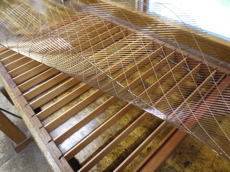
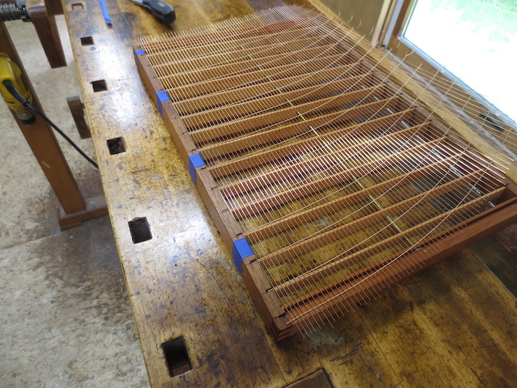
The mould is ready to receive its wire parts. A wire backing fresh off the loom is curvy but will flatten out when taped to the mould. This post will show how the backing was made.
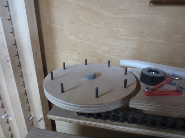
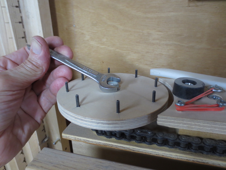
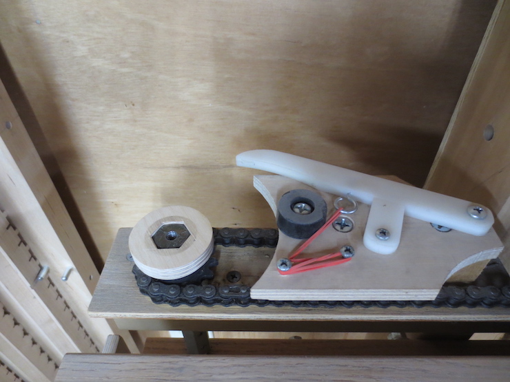
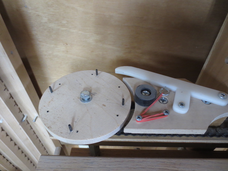
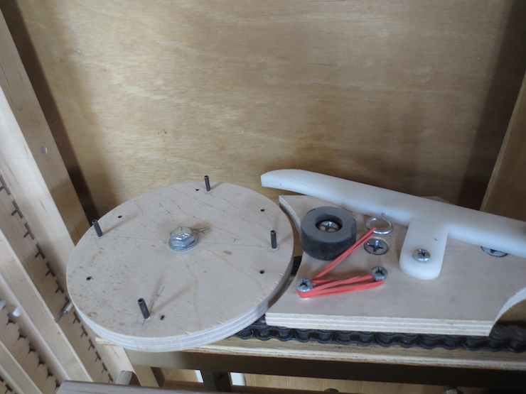
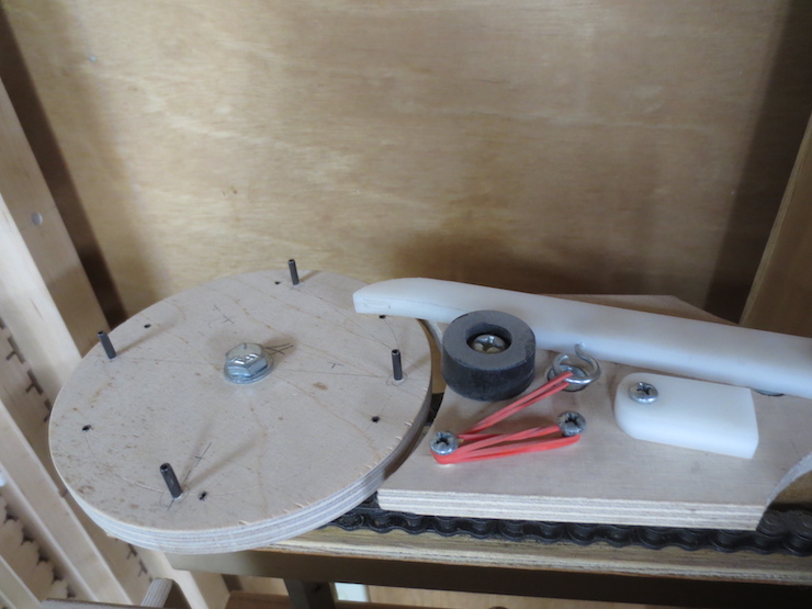
The counting wheel of the loom must be changed from 8 pins (previously used for the laid facing) to 4 pins to make my standard laid backing. On this loom 4 pins and 9 ‘clicks’ yields a spacing of 5.78 wires per inch. (‘Clicks’ refers to the sound the pawl makes as it drops off pins as the wheel is turned.) The twin lead screws of this loom are fixed at 13 threads per inch but the number of pins and the number of clicks can be changed to produce a number of different laid facings and backings. A simple formula calculates the wire spacing: Pins x thread (fixed at 13) / clicks = wires per inch. (In this case: 4 x 13 =52 then 52/9 =5.78. ) The laid facing made with the 8 pin counting wheel used 5 clicks to make 20.8 wires per inch. (8 x 13 = 104 then 104/5 = 20.8.)

This is about the heaviest wire that is useful for making chain wires. It is .015″ diameter soft phosphor bronze and makes the chain wires for this laid backing. Wove backing uses a .013″ diameter wire for a narrower space between laid wires. Laid facings can use almost any size chain wire between .012″ and .008″ diameter.
These spindles have recesses on one end and can be oriented in two ways. Using them with the recesses on top narrows the angle at which the wires are twisted for more widely spaced backing wire. Turning them over flat side up widens the angle for the tightest twist, more useful for laid facings.
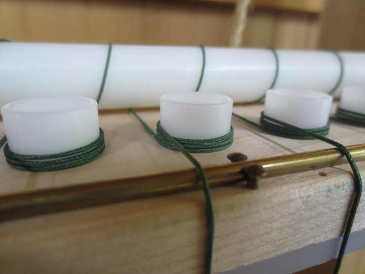
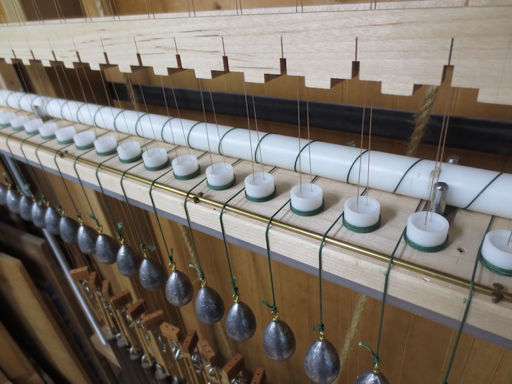
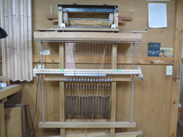
As many spindles as needed are put in the holes in the spindle rack. Then they are wrapped with the weighted cords that drive them to twist the wires.
The spindle holes will need aligning after all are connected to drive weights.
After all spindles are rigged with cords and weights they are aligned by turning them clockwise. They can’t be turned backwards; the cords tighten and prevent turning counter-clockwise.
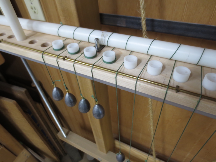
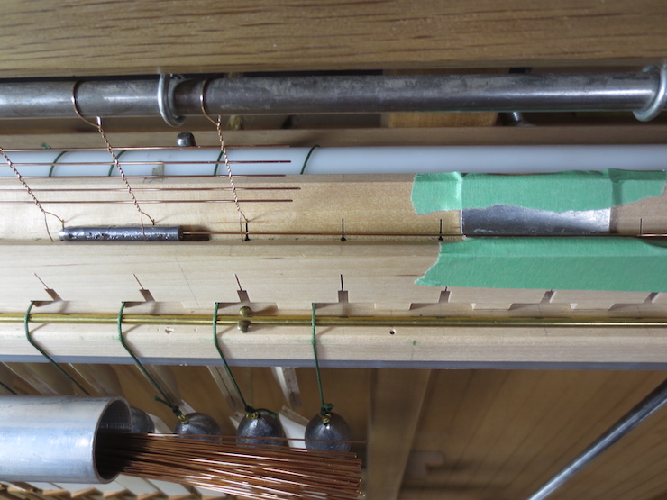
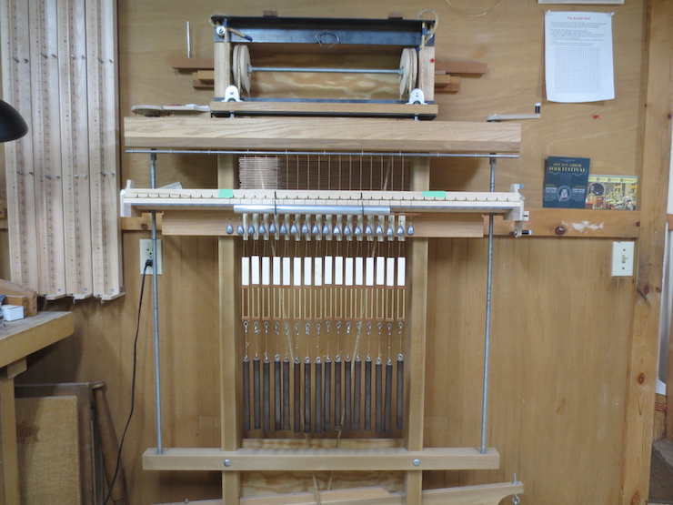
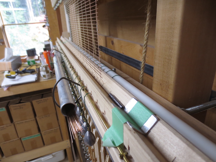
The spindles are ready and the wire trough is placed above them. For now it is elevated on posts to make it easy to string up the loom with the chain wires. Lined up along the wire trough are ‘wire slides’, one for each pair of chain wires. They are used along with wire spacers to keep the wire from twisting below the spindles.
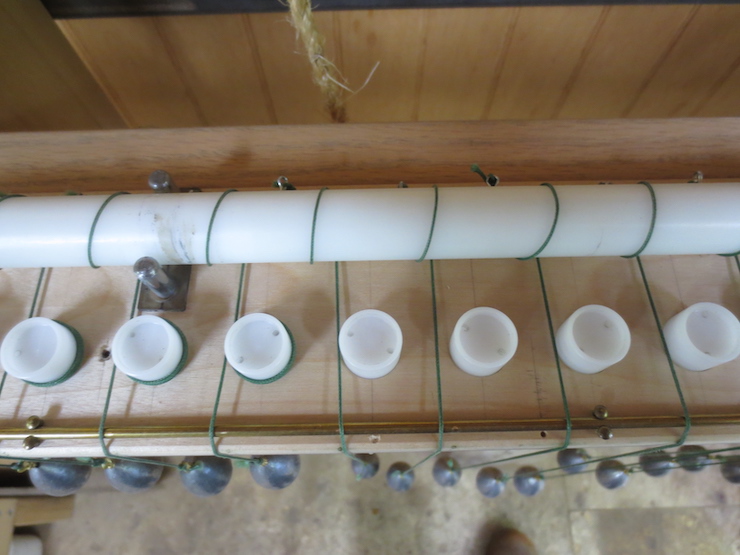
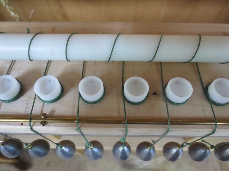
Lengths of wire have been draped over a bar at the top to form pairs. The two ends of each wire pass through a cross-wise slot in the wire trough, down through holes in the spindles, through holes in the wire slides and are twisted tightly together at the bottom. Then a one pound weight is hung on the wire slide at the end of each pair to hold the wires taut.
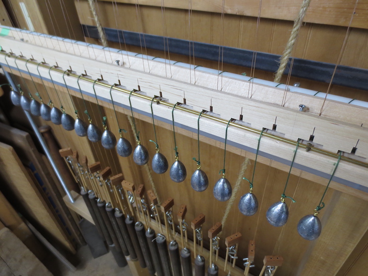
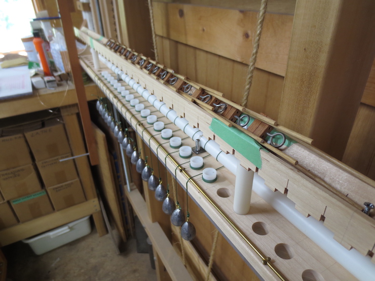
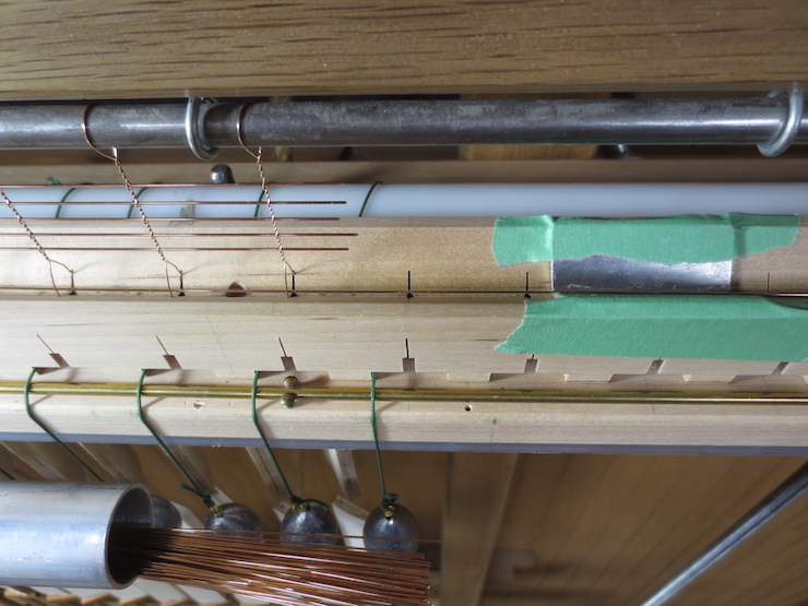
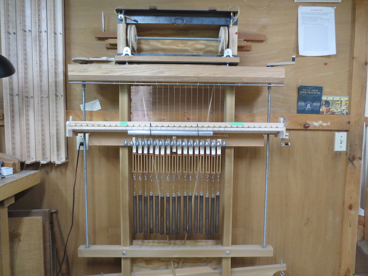
The posts have been removed and the trough lowered over the spindles. You can see three of the five screws that will be tightened to hold it in place.
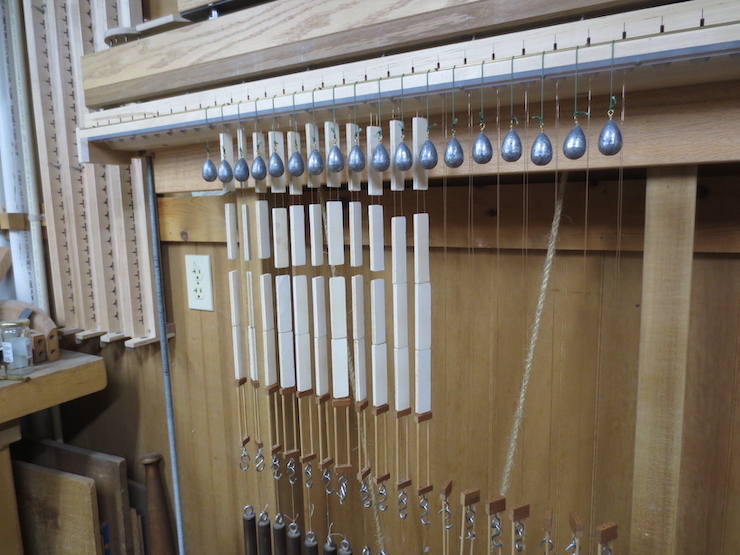
Wire spacers are installed below the twisting mechanism and above the wire slides. They are pieces of foam board with narrow slots cut in the sides for the wires to rest in.
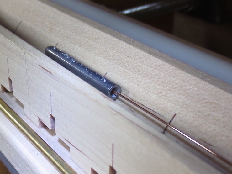
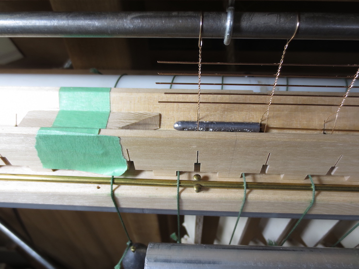
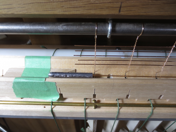
The laid wires are hand straightened and slightly curved so they need the help of this wire guide to slide through the row of upside down “Y” shaped openings in the wires. The wire guide is made of lead to be as heavy as possible for its small size. The guide is pushed along by the laid wire and removed after reaching the end. You can see this in the slide show sequence below.

This shows how the wire guide is employed. Halfway through the the sequence the view switches to the left to show how the guide is removed. After this step the backing is lowered onto the newly inserted laid wire (by releasing the treadle) and the chain wires are given three half-twists to bind it in place. The twisting mechanism is then lowered the prescribed distance (9 clicks), the treadle lifts the backing and the sequence repeats. Each time another laid wire is added the backing grows wider.


This sequence of photos shows how the twisting mechanism moves down as the web of wires grows wider. Notice how the (white) wire spacers slide down the wires and that a row of them is removed periodically.

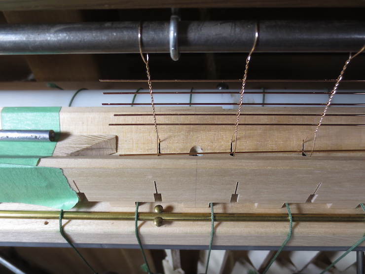
Some of the parts of the loom are labeled here. The wire lifting beam lifts about 1/2″ when the treadle is stepped on. This lifts the chain wires so a new laid wire can be slid down the trough between their splayed ends. With this loom different spindle rack/wire trough sets must be substituted to change the chain wire spacing. The narrowest spacing possible for this loom is 13/16″ on center.

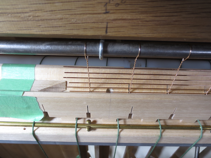
These chain wires are 1-1/8″ apart here and match the rib spacing of the mould.
The aluminum angle taped in place helps guide each laid wire into the small hole in the end of the wire guide.
The first step of fitting the backing.
More Information about the Loom
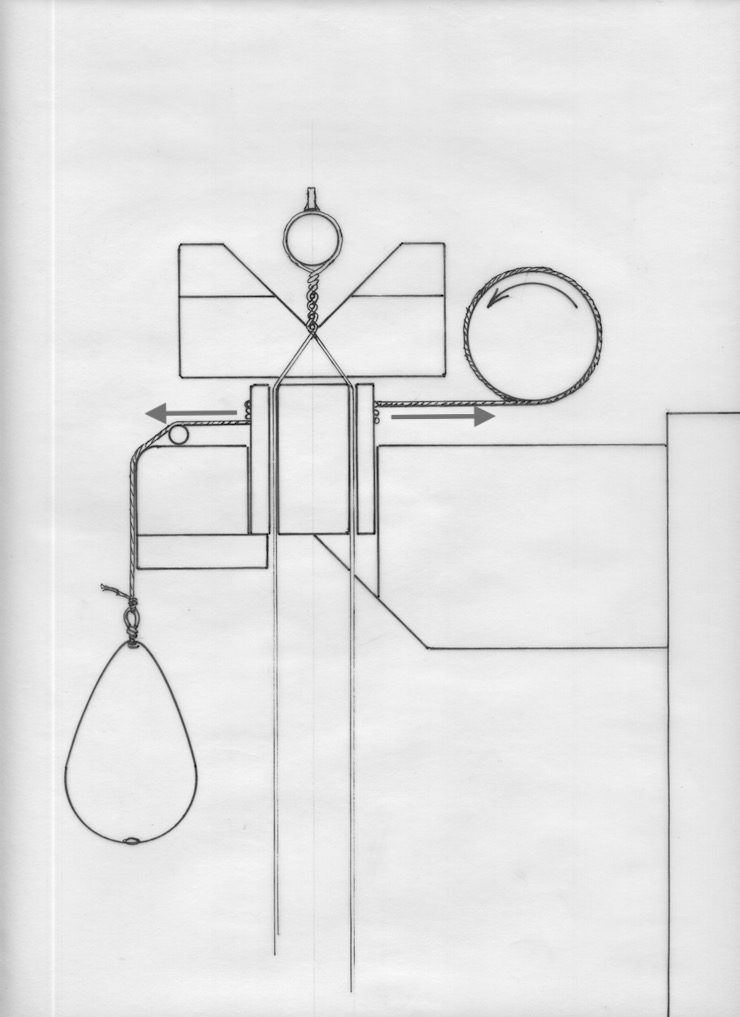
This drawing shows a cross section through a spindle, wire rack and wire trough. When the twisting crank is turned (in the direction shown by the curved arrow) the cord is reeled in and the spindle is turned. When the cord is pulled to the right it is tightened from two directions (as shown by the two straight arrows) so it cinches down on the spindle and turns it. This twists the pair of chain wires 1/2 turn.
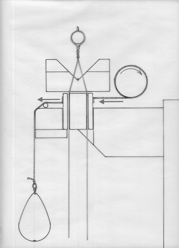
After a laid wire is added by twisting the chain wires the whole ‘web’ is lifted by the treadle (not shown). This engages the untwisted parts of the chain wires in the cross-wise slots in the wire trough. This prevents the spindles from turning backwards when the weighted cords are released by reversing the twisting crank. The cords slip on the surfaces of the spindles since the cord is only pulled from one direction (the weighted end). The spindles re-align themselves each time the cords are released.
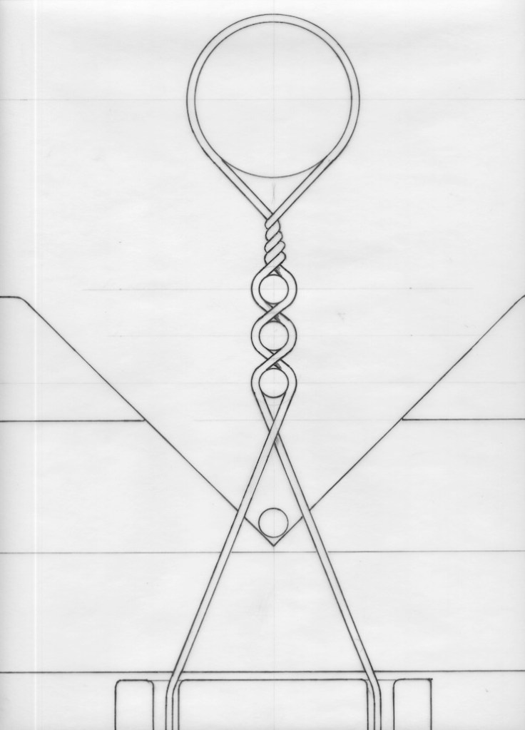
In this cross section drawing the web is lifted and a laid wire has been slid into place beneath the twists.
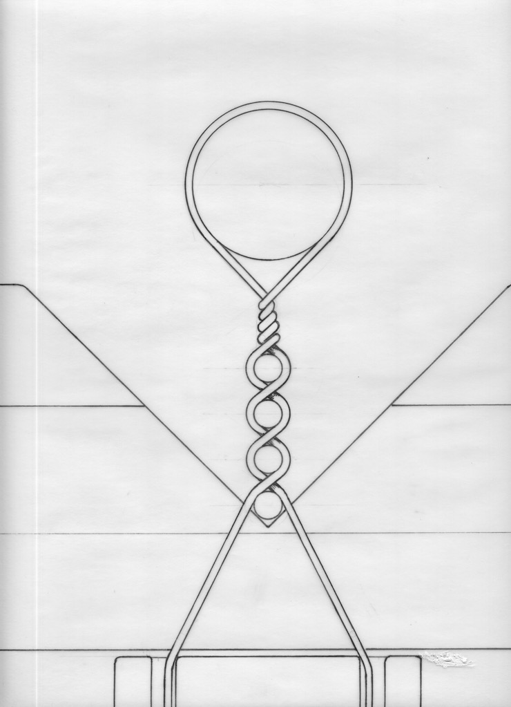
The foot treadle is released and the web is lowered down onto the laid wire.
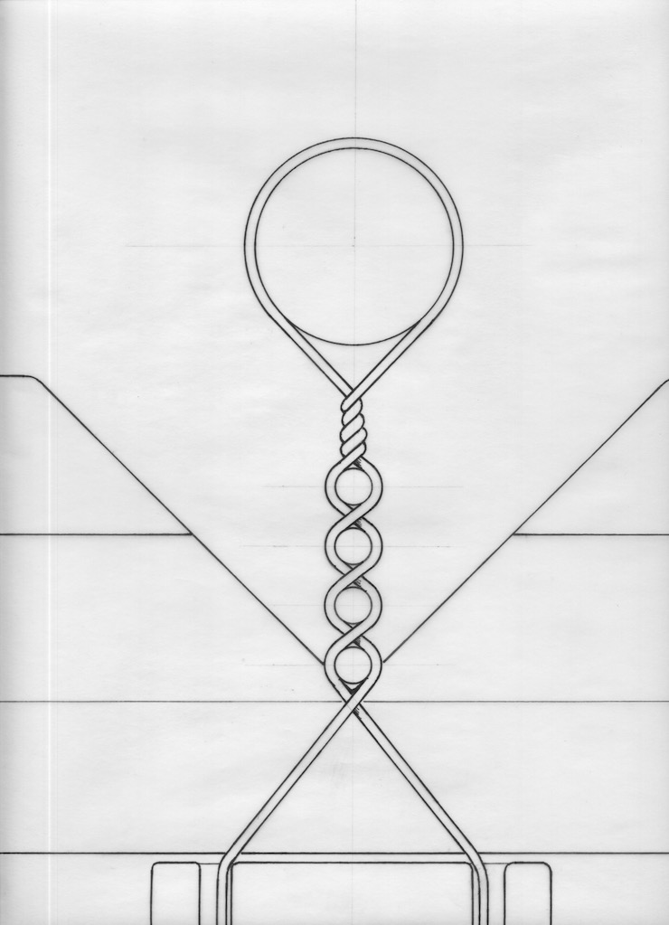
The chain wires are all given a half twist, adding one new laid wire to the facing. If a backing were being made the twisting sequence would be repeated two more times before adding another laid wire to the web. The web must be lifted each time since the mechanism allows only one half turn of the spindles at a time.
Logically the next post in this sequence would be “Making Laid Facings” but it will be skipped because it was posted previously and can be easily referred to.
