This post covers the remaining steps needed to prepare a double faced laid mould to receive its wire facing and backing. The topic of ledges and how they relate to backing wires in wove and laid moulds seems to need some explanation. It is important to understand the purpose of these structures so this post contains some additional information not directly concerned with actually ‘doing the work’.
Backing wire and the need for Ledges
Ledges aren’t essential for the single-faced laid mould, the oldest and simplest European style paper mould. I’d guess that many single faced laid paper moulds have been made without them, with the tops of ribs and mould frame made to form an unbroken flat surface. When covered with a laid facing the results can be pretty good.
But for double-faced moulds, laid or wove, this doesn’t work. In order for the upper layer of wire to be supported at the sides and the ends of the mould the lower layer of wire (backing) needs to be set down into the frame.
The solution is to lower the ribs and create recessed ledges at the ends of the mould. The ribs and ledges together support the wires of the backing so that it, in turn can support the wires of the uppermost layer, the wove or laid facing, at the proper level. The ledges have a second, perhaps incidental function. This is to trap the ends of laid wires to arrest their tendency to work out of the ends of the mould. This is the reason that I use ledges for single faced moulds even though they aren’t essential.
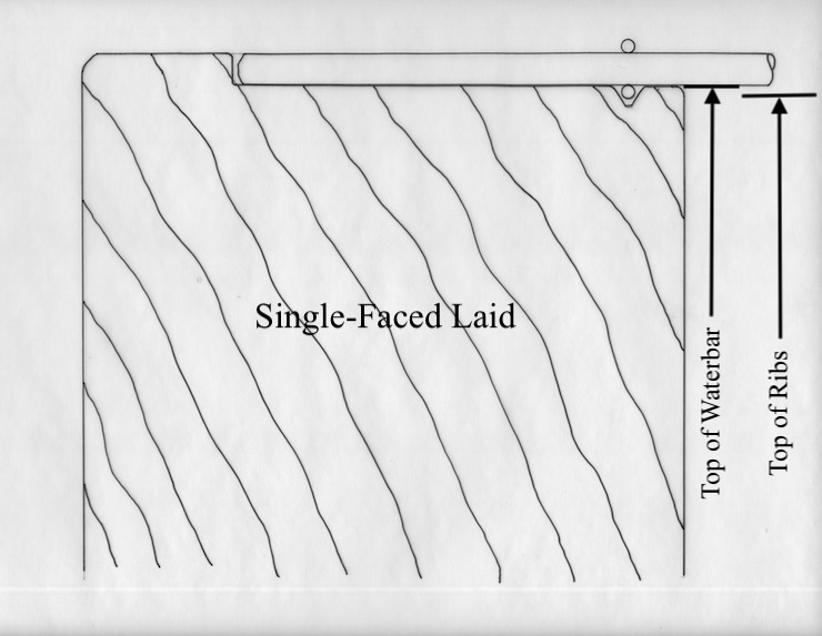
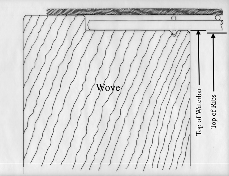
This represents a cross section through one end of a single faced laid mould; this part of the frame lies parallel to the ribs and perpendicular to the laid wires. A simple ledge is shown, as deep as the diameter of the laid wires resting in it. The drawing also indicates the level to which the waterbars (not shown but just off to the right) will be trimmed. Their tops should be at the same level as the ledge because the laid wires should rest on both. The tops of the ribs (which would be farther off to the right) form a plane at a slightly lower level. This is to account for the thickness of the chain wires of the laid facing. Copper edging that will be added to protect the wire ends and bind them to the top of the frame is not shown in these drawings.

The simple ledge of a single-faced laid mould. The waterbar has been leveled at the same time as the ledge was created. The ledge is recessed by the diameter of the laid wires so their top surface ends up even with the top of the wooden frame.
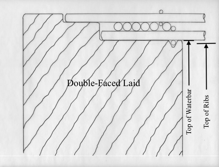
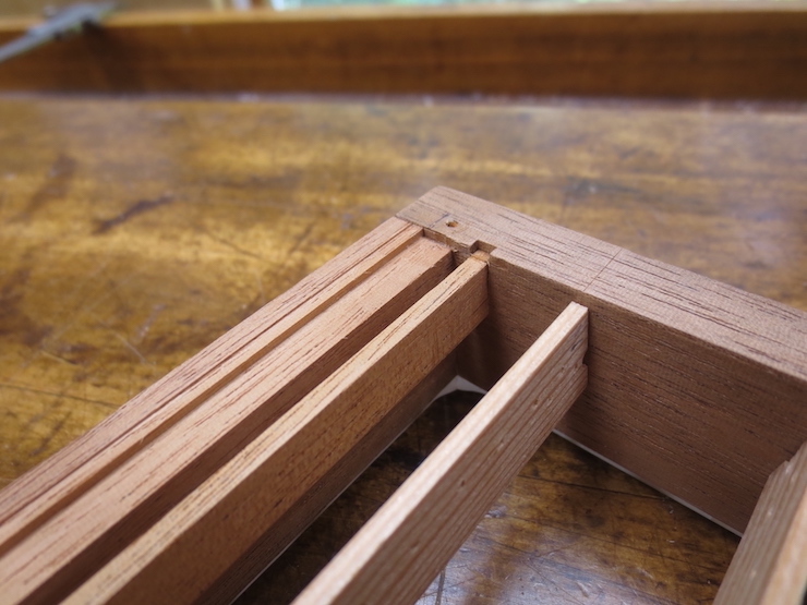
A double-faced laid mould needs a deeper ledge. Making it in the form of two steps avoids weakening the mould frame along the outer edge. Backing laid wires rest on the lower level. These, along with bridge wires, provide a firm base for the laid facing. The narrow groove along the inner edge of the deeper ledge traps the un-sewn ‘loose’ chain wire at each end of the mould so it can’t shift sideways along the laid wires.
The more complicated ledge of a double-faced laid mould. The upper laid wires should be even with the top of the wooden frame so the backing wires must be set lower to make this possible.
This shows the various wires of a double faced laid mould and how they are situated in the ledge.
One does not need to be so fussy when fitting wires to a wove mould but the backing still needs to be recessed to support the wire mesh level with the wooden frame.
The ledge of a wove mould is similar to that of a single-faced laid. It is a little deeper and the margin at the outside edge is wider.
Creating the ledges and leveling the waterbars.
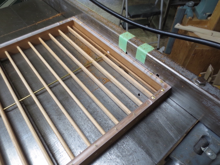
The ledge is created using a router table which in my shop is the wing of a tablesaw modified to allow a router to be mounted beneath.

The dial indicator was used to set the router bit to make the cut as deep as the thickness of the layer or layers of wire.
The waterbar has also been routed to the same level as the lower ledge. The table saw fence must be adjusted for the bit to reach over to the waterbar.
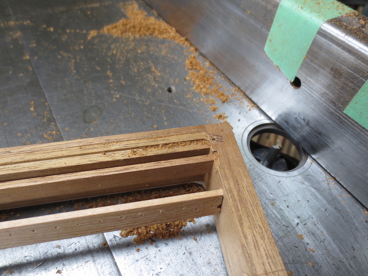
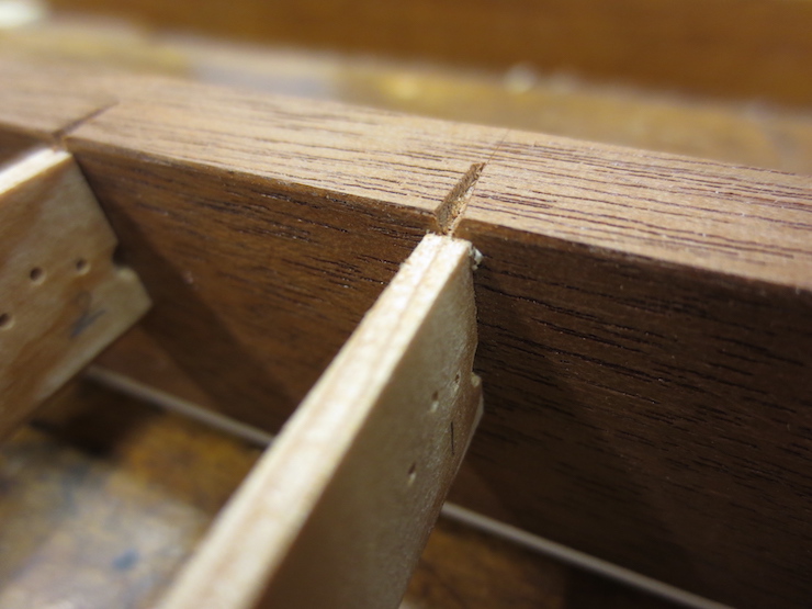
Straight from the router…
.. and with corners cleaned up with a chisel.
Making the Trap Groove

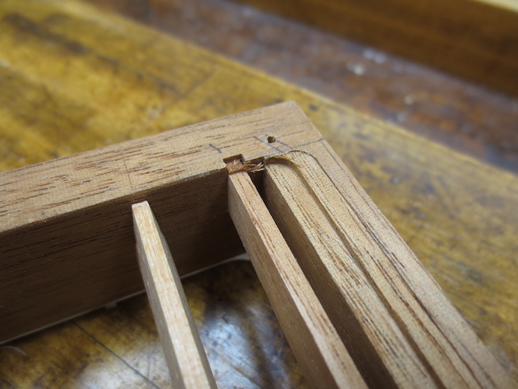
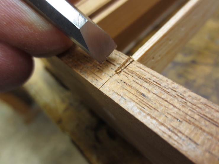
This pointed router bit is used to make the trap groove.
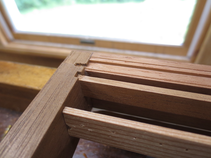
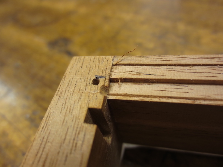
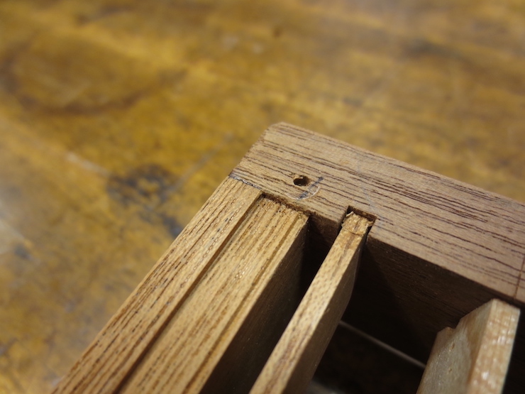
The trap groove has been routed and a notch has been chiseled, extending the bottom of the groove and making room for the ends of the chain and bridge wires.
A few more details

I route out a little area at the corners where adjoining pieces of copper strip will overlap. It is the same depth as the thickness of one strip (.015″) and will keep the strips from bulging up at the corners where there will be two layers.
The edges of the mould frame are eased off with a plane and lightly sanded.
Notches for the Twists
Laid wires will reach only to the inner edge of the mould frame but the twists must lap over it. This single-faced laid mould needs very small notches for the twists..
They are a little deeper for the backing wire twists of a wove mould.
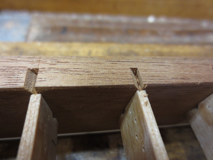
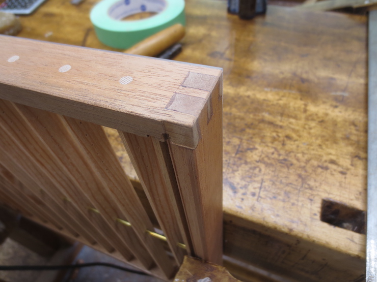
Notches for a double faced laid mould are a different story. A bundle of wires will need to fit in each notch so it must be roomy. Each notch will accommodate the ends of the upper chain wire twist, a bridge wire, and the lower backing wire twist. If these wires are too crowded the springy bridge wire will veer off to the side making it impossible for the chain wires to lie straight on the rib.
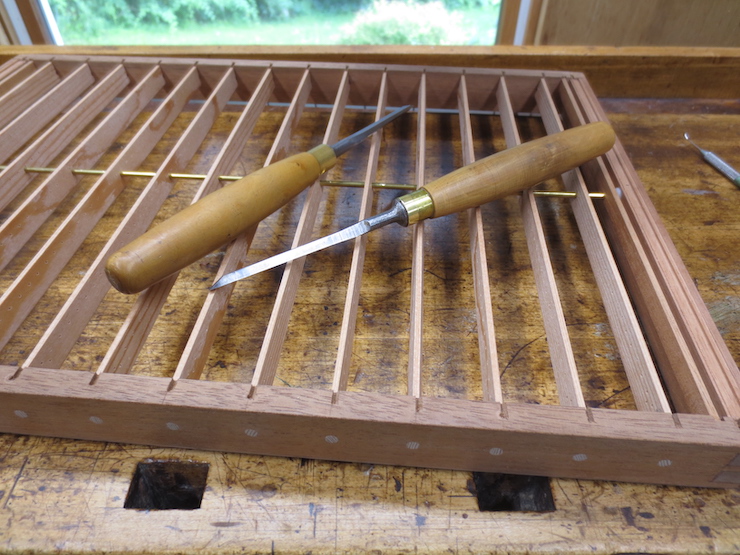
A double-faced laid mould frame with notches completed.
Applying Finish
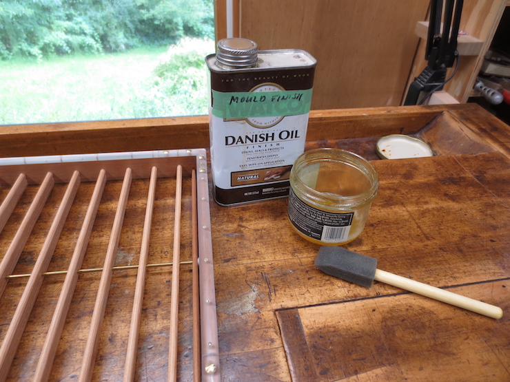
I’ve been using Watco oil as a finish. It dries a little more predictably than boiled linseed oil and makes the new mould look nice. Either is fine; both will wear off before too long! It is pointless to try to waterproof the wood of a paper mould. Water will inevitably get into the wood and a surface coating like urethane varnish will eventually start flaking off. I believe that untreated wood is better for forming sheets. Water flows more evenly along wet wood than over a shiny, hard surface. Wood is hydrophilic and attracts water. Water is attracted to wet surfaces and can flow smoothly there. A varnished surface is hydrophobic and repels water so water beads up and flows unevenly.
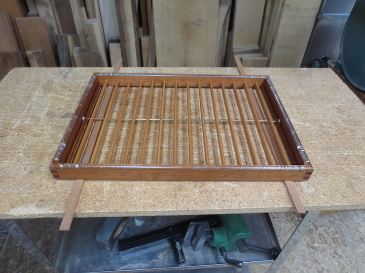
When the finish dries the mould will be ready to receive its wire facing.
