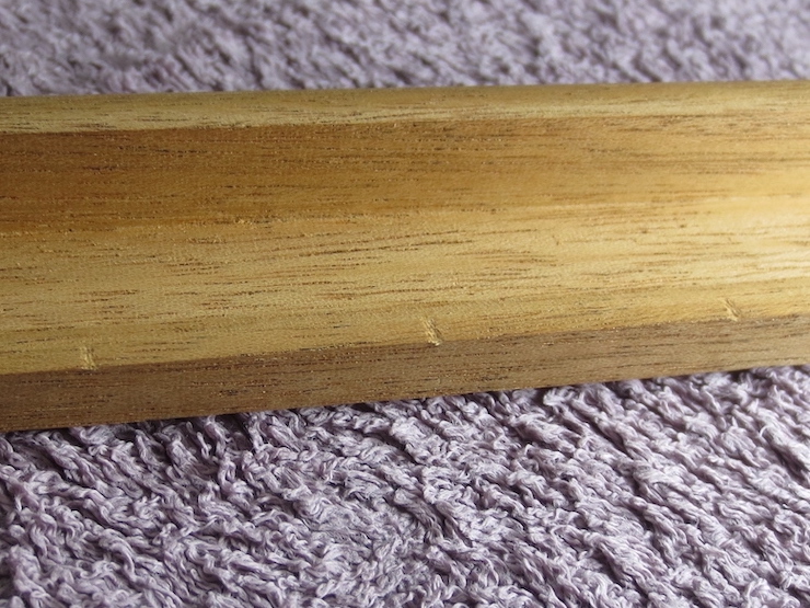
If the deckle belongs to a laid mould small grooves are filed into the rim where the chain wires stick up.
Placing the deckle on the mould and rubbing it around will cause the chain wires to leave visible dents in the wood. The deckle is turned 180 degrees and rubbed on the mould that way, too. (Or both ways on two moulds if it belongs to a ‘production style’ pair of two moulds and one deckle). If the chain wires were carefully aligned when making the mould they will match up both ways (or all four ways for a pair of moulds) and there won’t be a need to file extra grooves.
The dented marks are enlarged just a little at first with a file. Then the deckle is returned to the mould to check the alignment of grooves with chain wires. Some of the marks will be hard to see at first; deepening the ones that show first will allow the others to show up.
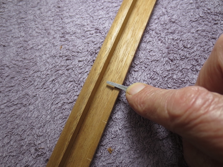
A ‘slim’ or ‘extra slim’ triangular file works well.
The notches should be deep enough that the rim rests on the laid wires to help make a neat edge on the paper.
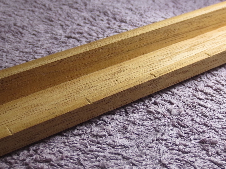
Shaping the Chamfers
The ends of the chamfers can be carved with a chisel.
The middle parts can be shaped with a spokeshave.
It is traditional to include small chamfers on the short ends of the deckle too. The purpose of these is not clear to me. (This may be important in some way for production use in commercial mills). The short sides have been left flat on top (not chamfered) for the moulds I’ve been making recently. I usually narrow the inner edges of the front and back to about 1/4″. Sometimes the deckles are left full depth on all four sides (with no chamfers at all) if thick paper is to be made. Over the years I’ve offered to make the inner deckle rims to any dimension but have received little feedback. 1/4″ seems to work well for most contemporary sheet forming methods.
This single facet chamfer would probably work fine but I broaden the chamfer up over the top surface in a gentle curve.
A cabinet scraper can be used as part of this process.
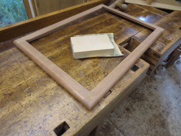
Sandpaper finishes the job.
The outside curves are also sanded.
The entire deckle is sanded with the exception of the four inside (vertical) edges which retain their original ‘jointed’ surfaces. Along their bottom edges (where they meet the deckle rim) the corners are left fairly sharp and eased only slightly with very fine abrasive paper. (320 or 400 wet/dry over a small block works well).
When the shaping is done I soak the deckle thoroughly to raise the grain as shown here. After it dries I give it a once-over with a fine sanding sponge before applying any finish. As with the wooden parts of the mould the finish can be boiled linseed oil, tung oil or Watco oil. The finish won’t last very long (and that’s OK). The deckle and mould are ready to use!
Following are some dimensions for deckle joints. I make two ‘weights’ of deckles; ‘light’ and ‘standard’ (which correspond to ‘light’ and ‘standard’ moulds). I have long felt that small moulds tend to be overbuilt and have recently ‘slimmed down’ the wooden parts of those smaller than about 16″ x 20″.
These joints are based on the old deckle joint that I examined in post #32. Do not rely on these figures as cutting dimensions; use them only as a guide to understanding the proportions when designing your own version.
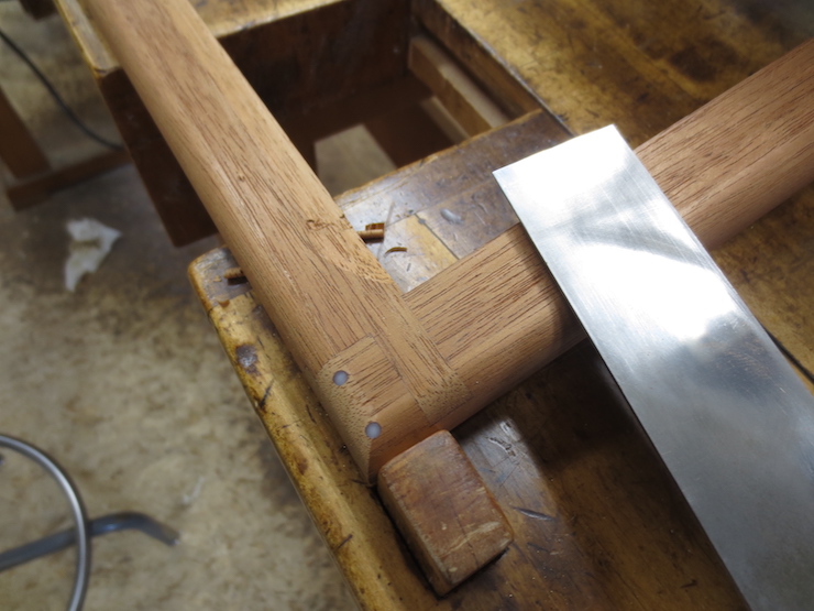
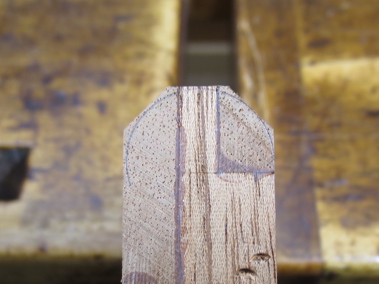
An Important Consideration
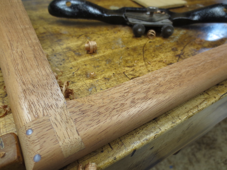
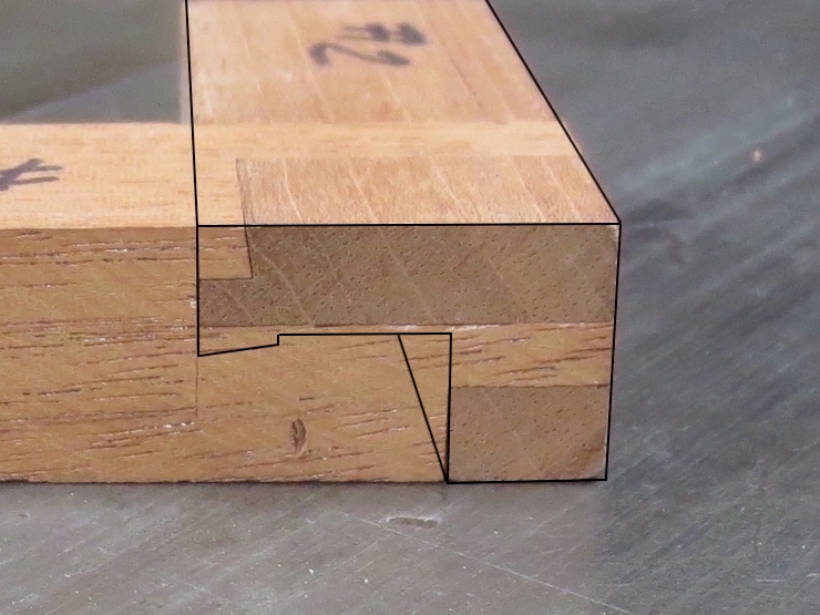
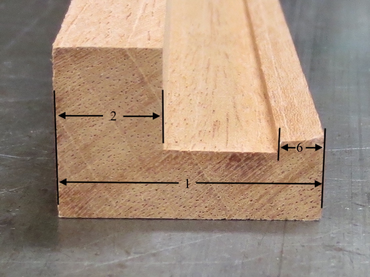
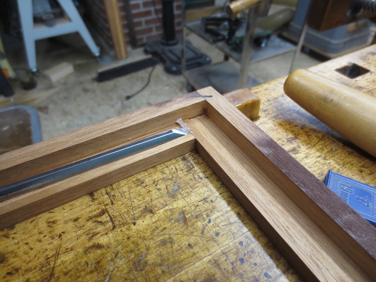
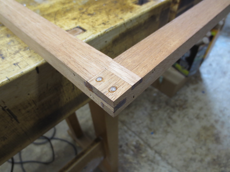
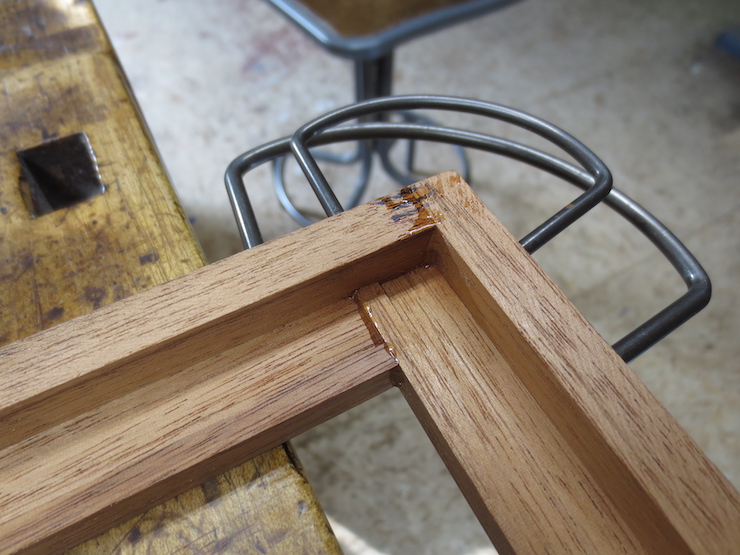
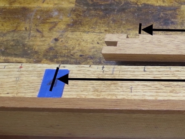
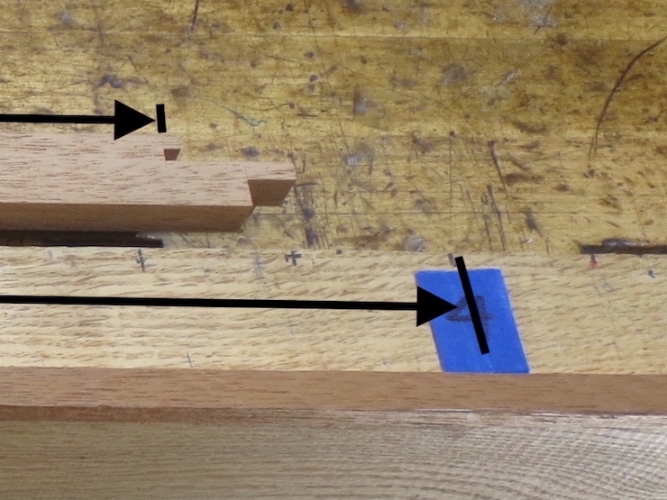
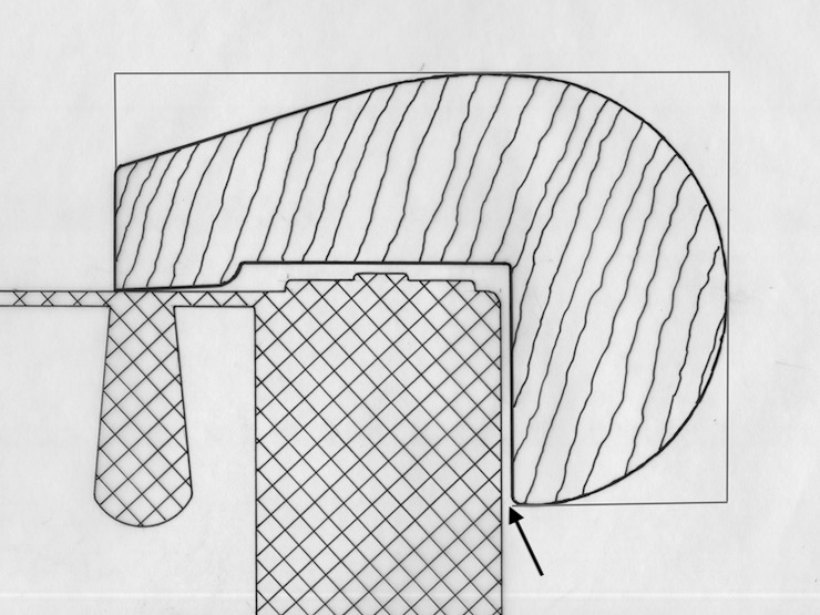
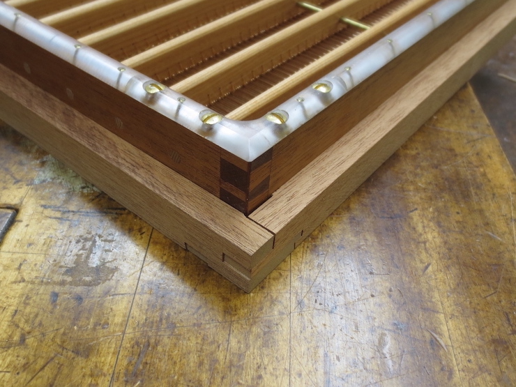
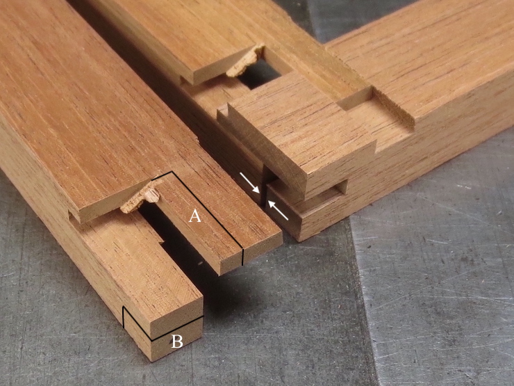
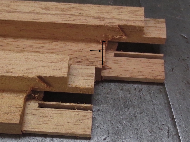
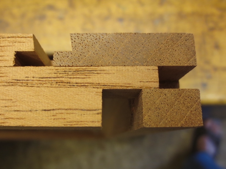
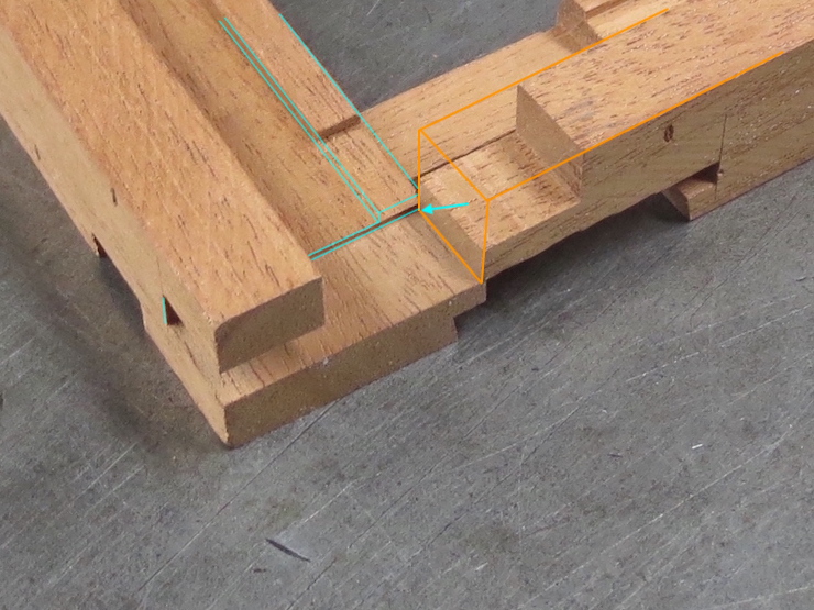
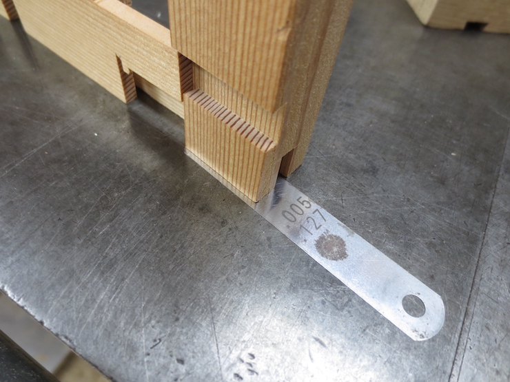
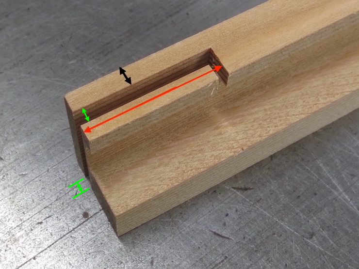
It is important that the channel behind the deckle rim is not so deep as to interfere with the joint. The photo above shows a narrow margin of ‘extra wood’ between the ‘bottom’ of the channel and the overhanging part of the joint. The black lines have been added to describe the shape of the deckle part prior to a joint being cut there. This shows how the shape of the part relates to the joint cut on its end. I now think it is best if the bottom of the deckle channel is in the same plane as this part of the joint. The dimensions outlined below will need to be adjusted to make this happen.
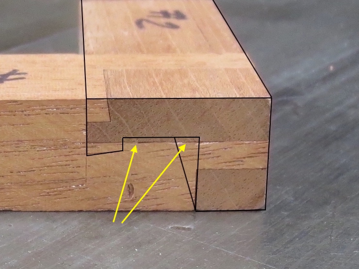
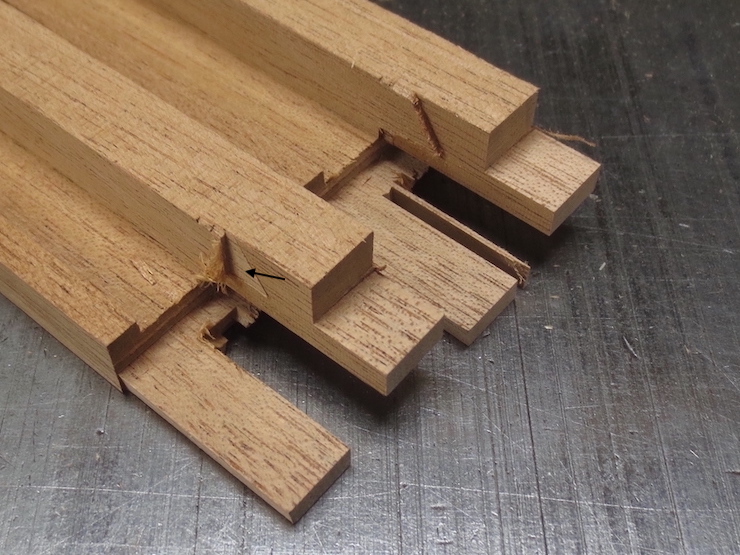
There would be a problem if this same deckle part had a channel cut this deep. A gap would be created where the arrows point. It is good to keep this in mind when designing the joint.
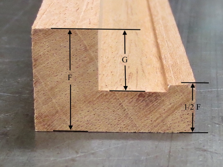
Dimensions of Deckle Stock
Both light and standard weights of deckle stock are described in inches and millimeters.
Light Deckle/inch
Light Deckle/mm
Regular Deckle/inch
Regular Deckle/mm
F = 3/4″
F = 19mm
F = 7/8″
F = 22.2mm
G = 7/16″
G = 11.1mm
G = 1/2″
G = 12.7mm
1/2F = 3/8″ *
1/2F = 9.5mm *
1/2F = 7/16″ *
1/2F = 11.1mm *
*This measurement is approximate and is left oversize until after the joints are cut in order to facilitate creating the special deckle rim curvature. (See post #38)
Light Deckle/inch
Light Deckle/mm
Regular Deckle/inch
Regular Deckle/mm
1 = 1-1/8″
1 = 28.6mm
1 = 1-1/4″
1 = 31.8mm
2 = 7/16″ *
2 = 11mm *
2 = 1/2″ *
2 = 12.7mm *
6 = 3/16″
6 = 4.8mm
6 = 1/4″
6 = 6.4mm
*The dimension given is the final dimension; it is used when planning the mould and deckle fit (posts #5 and #30). This is left oversize until after the joints are finished (see post #37).
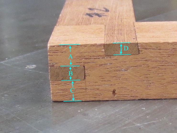
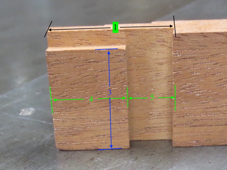
Sample Dimensions of Deckle Joint Parts
The charts give dimensions for two sizes of deckles in inches and millimeters.
Use this table of vertical dimensions for the photos immediately above and below.
Light Deckle/inch
Light Deckle/mm
Regular Deckle/inch
Regular Deckle/mm
A = 9/32″
A = 7.1mm
A = 5/16″
A = 8mm
B = 3/16″
B = 4.8mm
B = 1/4″
B = 6.4mm
C = 9/32″
C = 7.1mm
C = 5/16″
C = 8mm
D = 5/32″
D = 4mm
D = 3/16″
D = 4.8mm
E = 1/8″*
E = 3.2mm*
E = 1/8″*
E = 3.2mm*
F = 3/4″
F = 19mm
F = 7/8″
F = 22.2mm
*This dimension is the same in both deckles. It is impractical to make the slot any narrower than this.
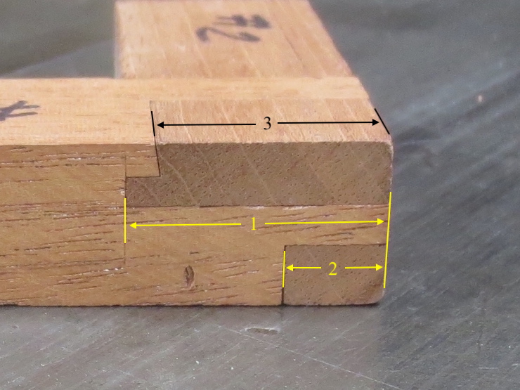
Use this table of horizontal measurements for the photos immediately above and below.
Light Deckle/inch
Light Deckle/mm
Regular Deckle/inch
Regular Deckle/mm
1 = 1-1/8″
1 = 28.6mm
1 = 1-1/4″
1 = 31.8mm
2 = 7/16″
2 = 11.1mm
2 = 1/2″
2 = 12.7mm
3 = 1″
3 = 25.4mm
3 = 1-1/8″
3 = 28.6mm
4 = 11/16″
4 = 17.5mm
4 = 3/4″
4 = 19mm
5 = 7/16″
5 = 11mm
5 = 1/2″
5 = 12.7mm
6 = 3/16″
6 = 4.8mm
6 = 1/4″
6 = 6.4mm
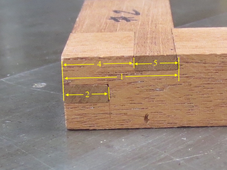
Some Dimensions for the Mortise End
I make this end of the joint first. I ‘shoot’ for the dimensions shown and then ‘make’ the other side fit. Slight dimensional errors made when cutting this side of the joint can be corrected with corresponding adjustments to the other side. Not all dimensions are given here; some must be deduced from the previous photos).
Light Deckle/inch
Light Deckle/mm
Standard Deckle/inch
Standard Deckle/mm
1 = 1-1/8″
1 = 28.6mm
1 = 1-1/4″
1 = 31.8mm
2 = 7/16″
2 = 11.1mm
2 = 1/2″
2 = 12.7mm
3 = 1″
3 = 25.4mm
3 = 1-1/8″
3 = 28.6mm
4 = 11/16″
4 = 17.5mm
4 = 3/4″
4 = 19mm
5 = 7/16″
5 = 11.1mm
5 = 1/2″
5 = 12.7mm
C = 9/32″
C = 7.1mm
C = 5/16″
C = 8mm
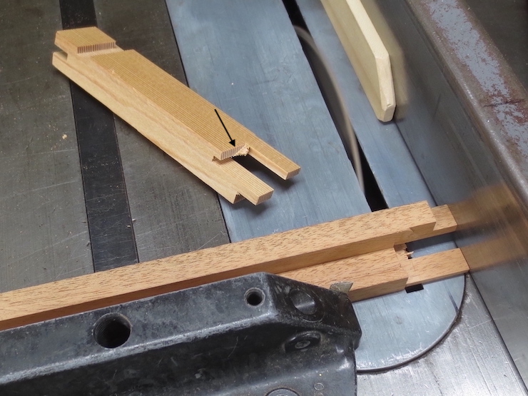
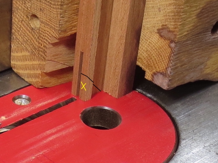
When making his joint the part labeled with the red “X” would not yet be trimmed away.
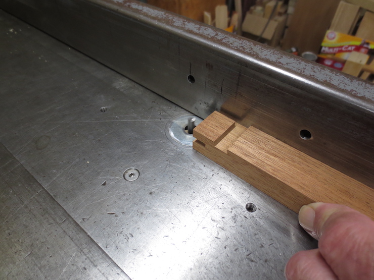
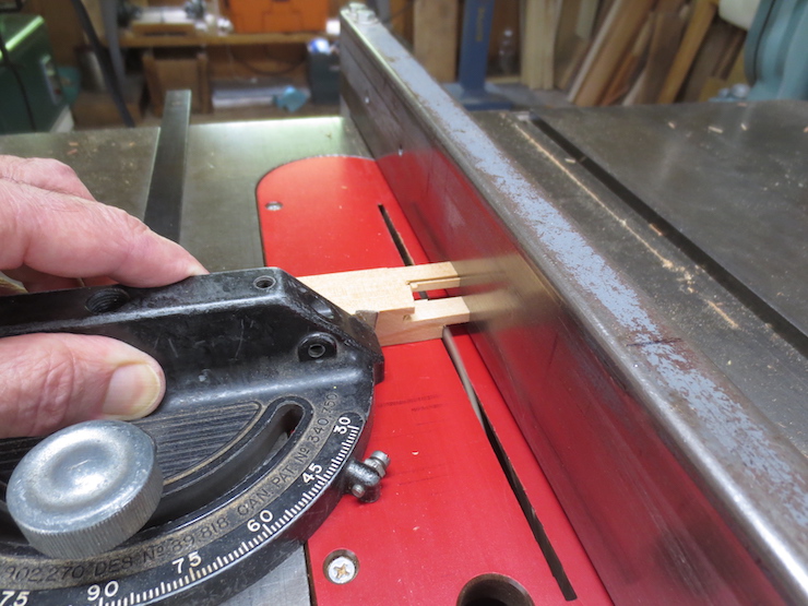
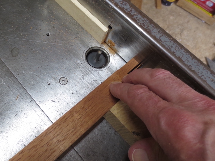
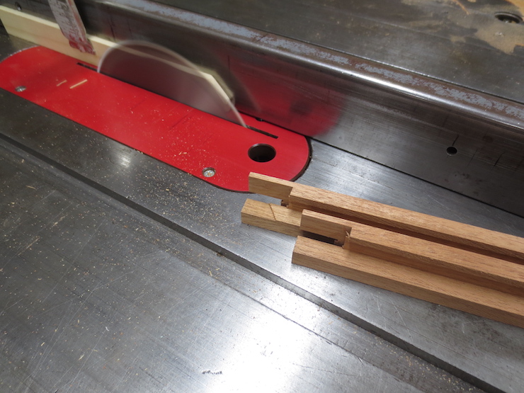
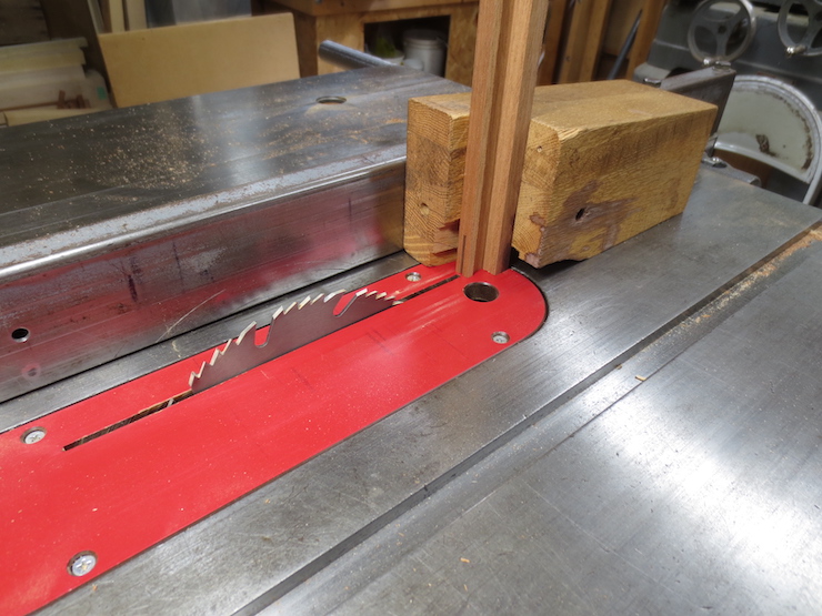
First the corners are sawed off at 45 degree angles.
This can be done on the table saw using this overhanging fence.
This roughing stage is finished.
The lower deckle has been partially rounded over with a router. One more fine cut will take off the last rough saw marks.
This is how the edges are rounded.
After the outside edges are rounded the front and back need to be chamfered to narrow the inner edge.
Roughing the Chamfer on the Inside Edges
Most deckles have chamfered areas along the front and back (long) sides. The inside edges of the deckle are narrowed to roughly correspond to the desired thickness of pulp to be collected on the mould. One way to rough out the wood is with this panel cutting bit. A spokeshave can be used later to smooth the angular surfaces into a gentle curve.
Rounding the Deckle Rim
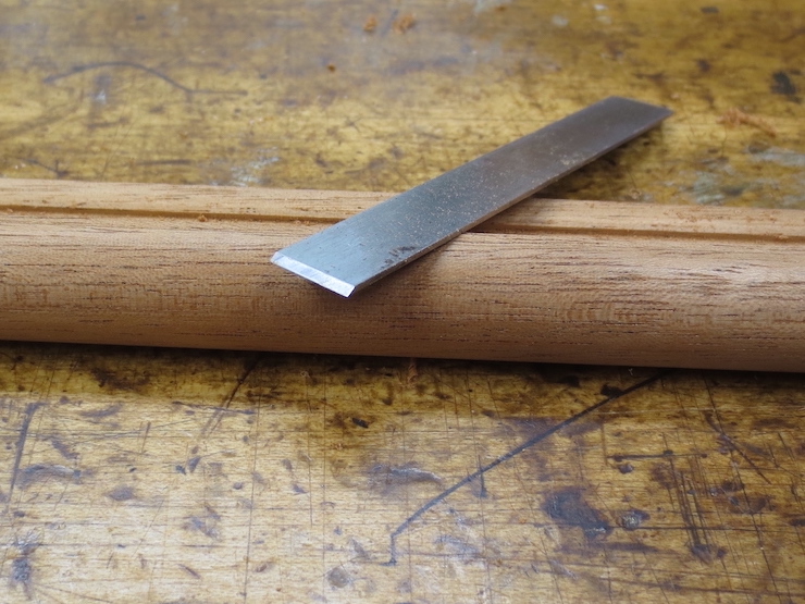
The inner edges of the deckle rim need to be rounded off so they don’t catch on the mould’s copper edge strip as the deckle is taken off the mould.
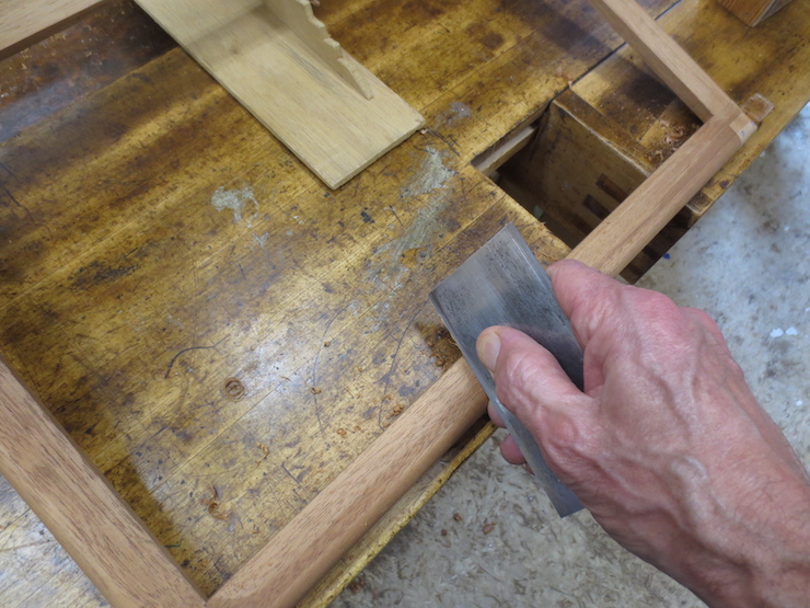
I do this by hand using this burred scraper. It’s the blade of the scraper plane that was used earlier to level the ribs.
First an even bevel is scraped the full length of each side.
The bevel is refined into a curve with the scraper then smoothed with sandpaper.
These last two photos may show the process more clearly.
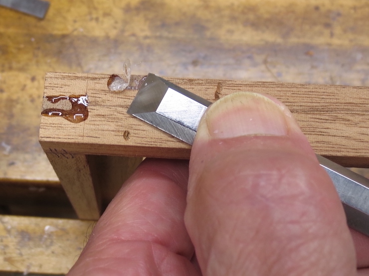
The clamps can be removed after a few hours, leaving hardened globs of epoxy here and there. But the epoxy stays sticky for a while so is best to let it cure overnight before removing the excess.
This can be cleaned up with a coarse file or with a chisel.
A chisel works best on the inside surfaces. This one has an offset handle to allow paring in hard to reach areas.
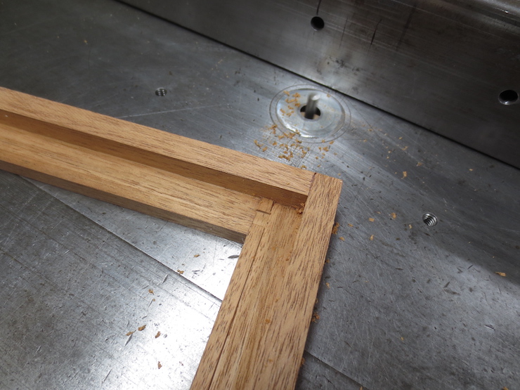
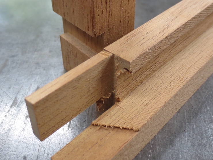
A little part of the deckle rim needs to be cut away at each corner. Some of the waste has been routed away at this corner and another pass will remove the rest.
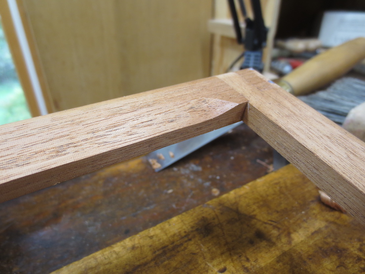
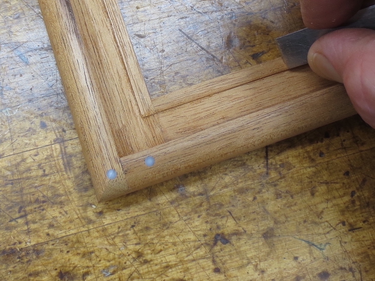
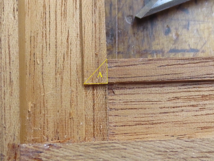
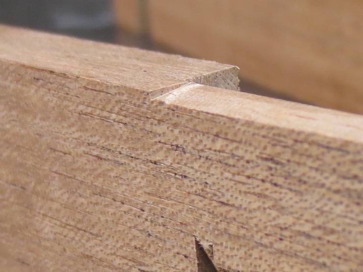
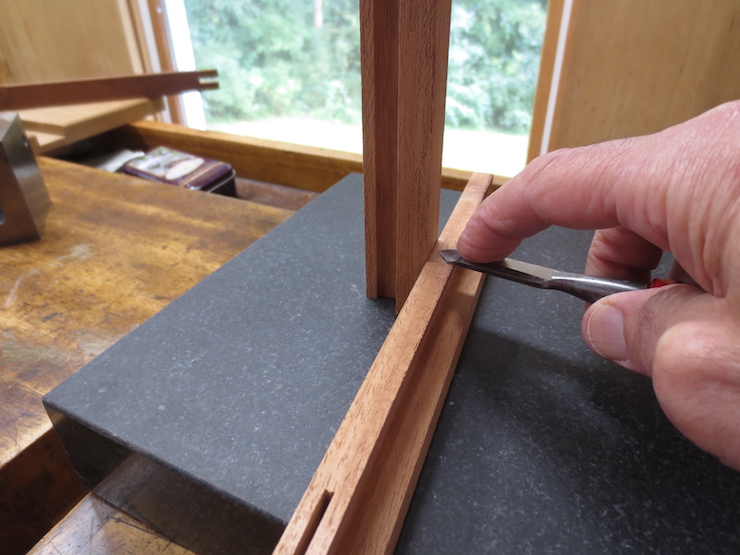
Since the rim of the deckle is slanted inward a little triangular area (A) will stick up just a little where it laps the adjoining rim. A sharp chisel laid flat on the adjoining deckle rim slices this off easily.
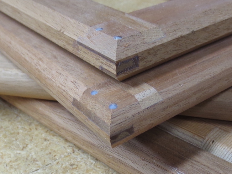
“Stapling” the deckle Joint
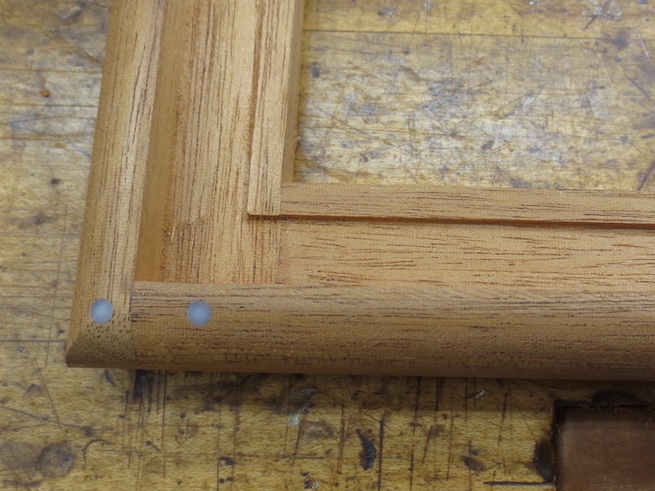
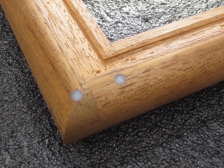
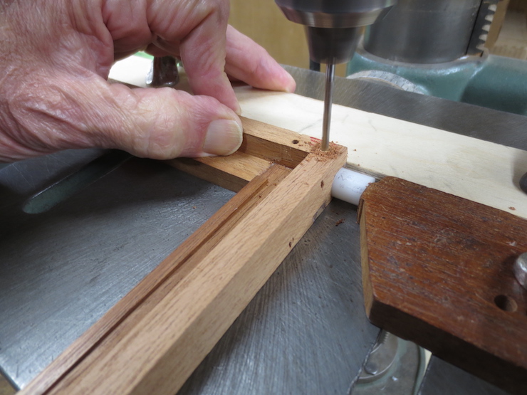
Above, a pair of 1/8″ diameter holes are drilled through the deckle at each corner.
Traditionally the deckle joints would be stapled with copper wire. The clinched ends of the staple would be hidden beneath brass sheathing that covers the deckle. This deckle is not to be sheathed (and the staples’ sharp ends wouldn’t be covered) so I substitute a pair of acetal pegs for each staple. These will be machined flush with the surface of the deckle.
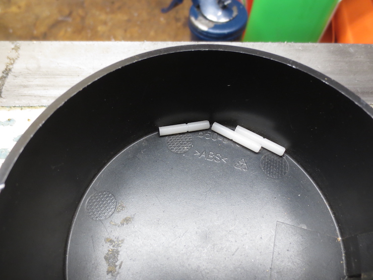
Lengths of the acetal rod are inserted and trimmed to length. The holes may need to be drilled larger to make the pegs fit. (The rods are supplied a little bigger than their nominal size).
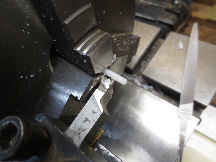
I turn a shallow groove on the pegs to lock them in place when they are epoxied in the holes.
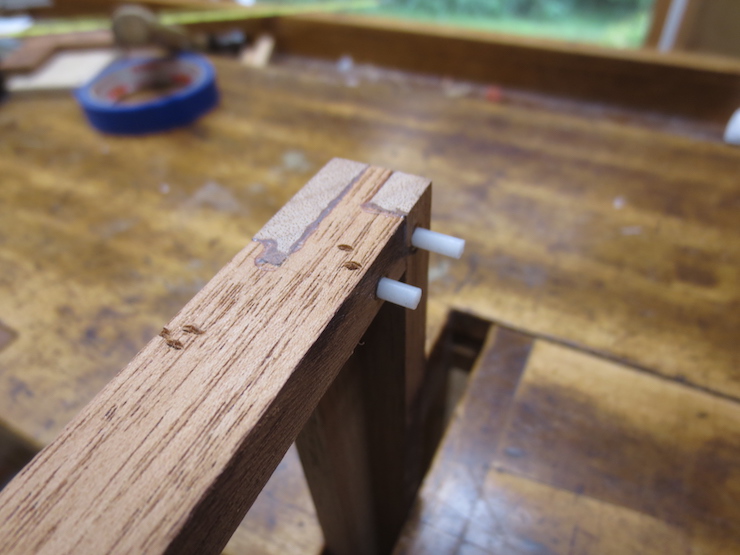
The pegs are started into their holes.
When they are tapped in place glue squirts out the other side.
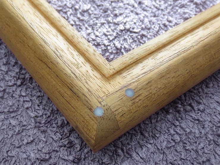
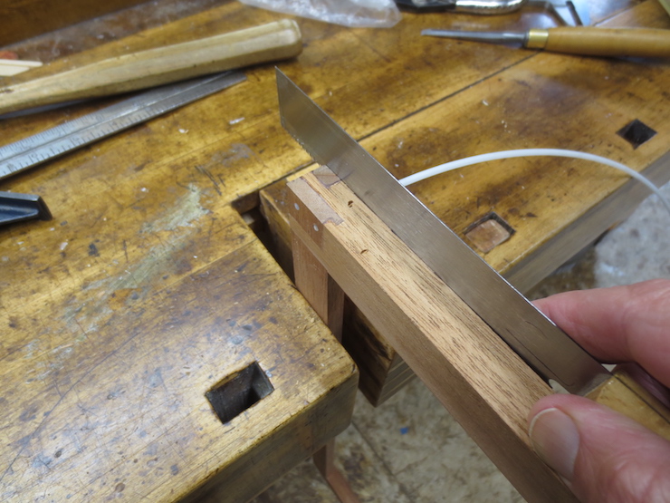
The pegs and cured epoxy will be filed flush before the deckle is shaped.
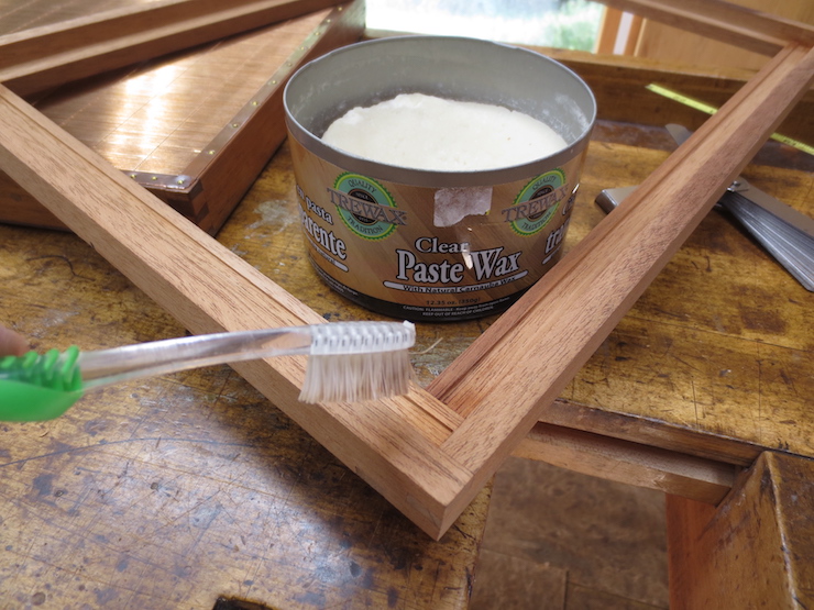
Applying paste wax to the outside of the parts makes it a little easier to remove the excess epoxy that squeezes out. The parts should be pushed up tight to keep the paste wax from getting into the joints.
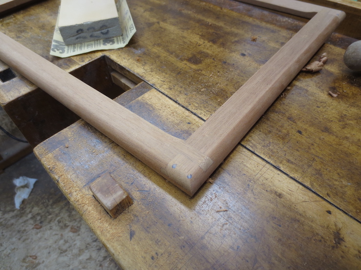
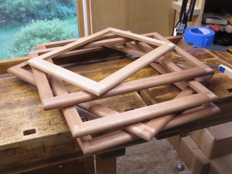
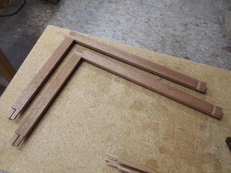
The deckle parts fit together in a rotating pattern so they have to be assembled in a specific way. First two opposite corners are joined, making identical “L” shapes.
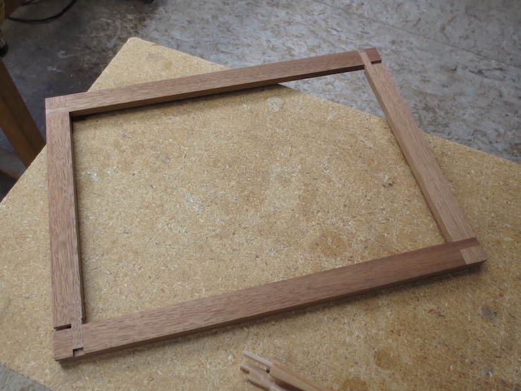
Then those “L”s are joined to form a rectangle. No glue here; these photos just show the sequence.
Epoxy has been applied to both sides of every surface in the joint (see the post “Gluing Moulds”). Then the parts have been fitted together and clamped. These picture frame clamps dig into the wood but they work well, putting pressure right where it’s needed. The edges will be rounded off anyway.
I leave the glue alone until after it hardens. Trying to remove the excess while it’s still soft just smears it all over.
The clamped deckle is set aside for the glue to cure.
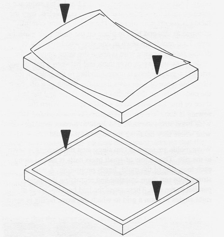
A deckle serves as a ‘fence’ to ‘corral’ a rectangle of pulp as it is deposited on the wires of a mould. In order for the edges of the paper to have neat ‘deckle edges’ the inner rim of the deckle is given a special shape, composed of very subtle convex curves on the two long sides and equally subtle concave curves on the short sides. This subtle shaping allows the deckle to ‘bite evenly’ against the wire surface of the mould when the deckle is pressed against the mould while dipping sheets.
In the drawings these curves are much exaggerated and the inner edge of the deckle is represented as simple lines. The ‘arrows’ in both drawings indicate the areas where pressure is applied by the vat person’s hands while sheets are being formed.
When the deckle is placed loosely upon the surface of the mould it will contact the flat wire surface along the midpoints of the two long sides as shown at the top. As the short sides of the deckle are gripped to the mould the wooden deckle will be forced to distort slightly and the curves will flatten, supplying a little extra pressure at the places where it is most needed; farthest from the hands. This is especially important for large moulds. If the edges of the rim were instead made straight the deckle would be more likely to ‘leak’ pulp in some areas, causing wild deckle edges.
This effect of these curves is very subtle, hard to see and impossible to photograph.
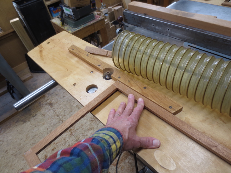
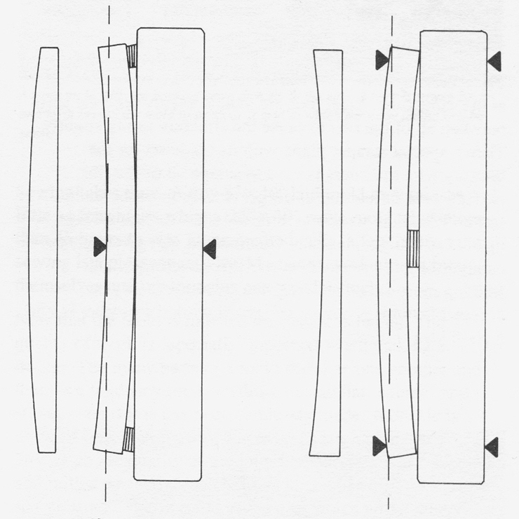
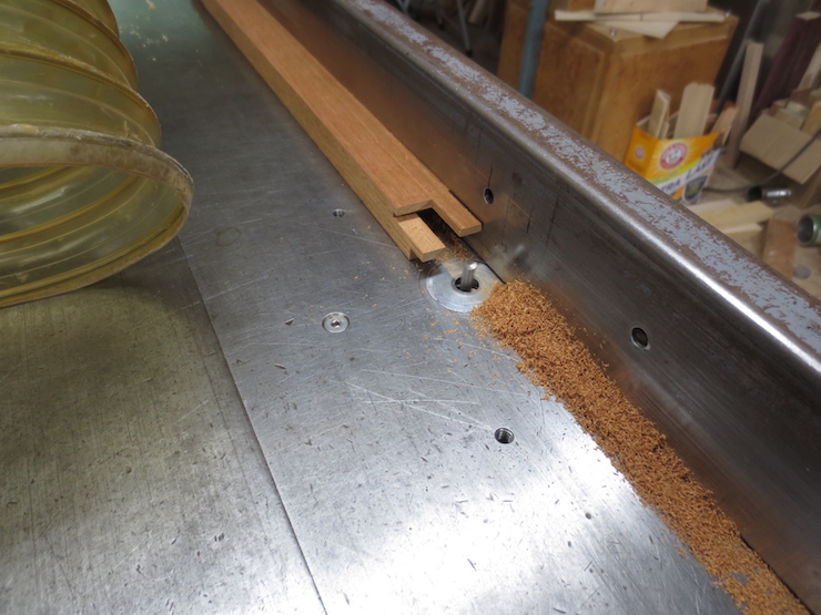
To create these very slight curves the deckle pieces are sawed, one at a time, while being bent and held against a straight beam. After the saw cut has been completed and the part released it will spring back to its original straight condition except for the inner rim which will have been given a convex or concave shape. This depends on which of the two ways (shown above) the piece was shimmed and clamped. The drawings simplify and exaggerate the shapes for clarity. The dashed lines represent the saw cuts. The arrows show where clamping pressure is applied.
On the left the part has been shimmed at both ends and pressure applied in the middle making it (temporarily) concave. When sawed straight (the beam is stout enough to stay straight) more is removed from the ends than the middle. When the part is removed from the beam it springs back to the shape shown at the far left, leaving a convex curve.
On the right the part has been shimmed at the middle and it is clamped against the fence at both ends. This reverses all of the effects to create the opposite result; a concave curve.
I hope the photos make this process clearer!
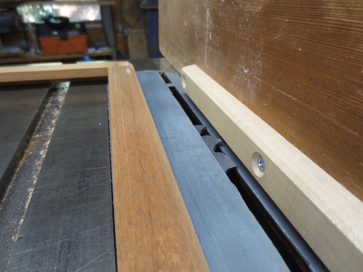
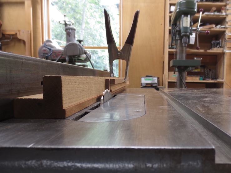
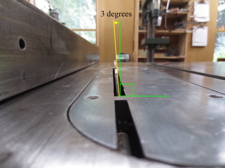
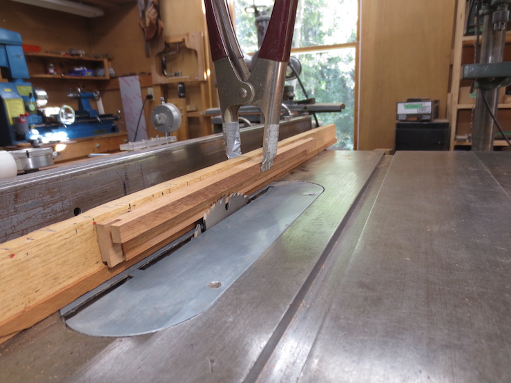
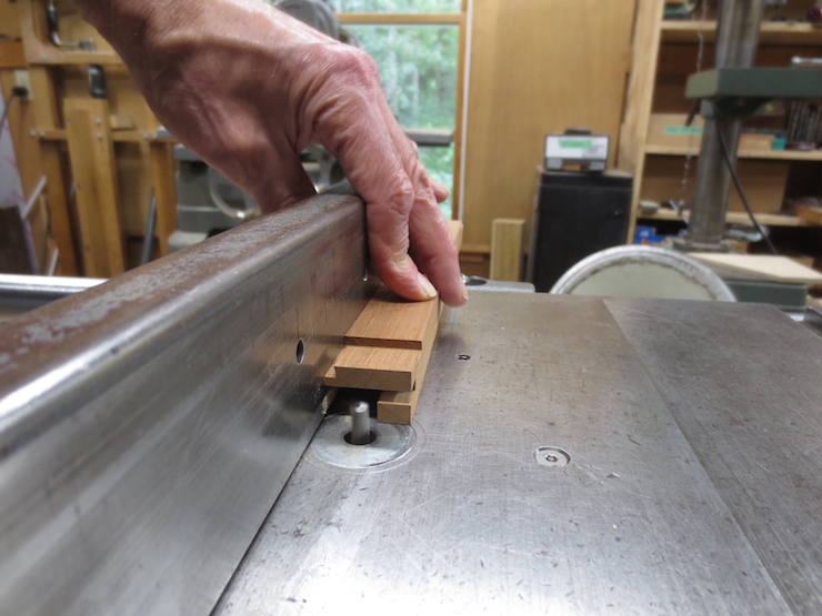
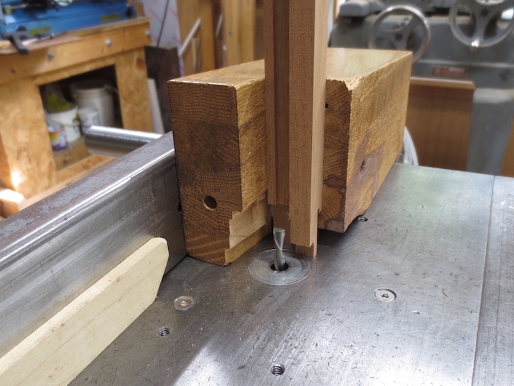
The beam is L shaped so that one edge can ride against the fence of the table saw while leaving room for the clamp (so it won’t hit the fence). The inner edge of the deckle rests on a ledge to help hold it in place. The smooth cutting hollow ground saw is tilted inward at 3 degrees.
One of the long sides of a deckle being sawn to create a concave shape along its rim.
The saw is tilted toward the fence by 3 degrees.
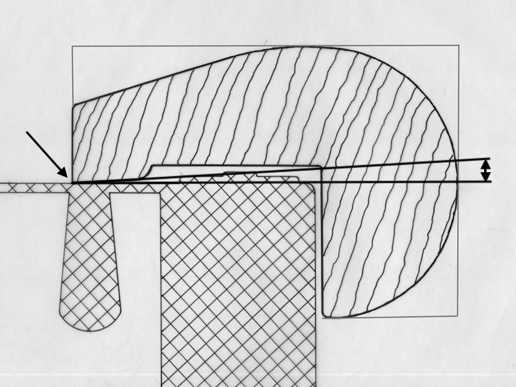
The effect of the 3 degree angle is shown here. Since the rim is cut back at an angle it touches the mould wires only along its very edge (where the arrow points), concentrating the pressure there.
Making a Convex Curve on the Front and Back
The long sides are cut first. Here’s the process:
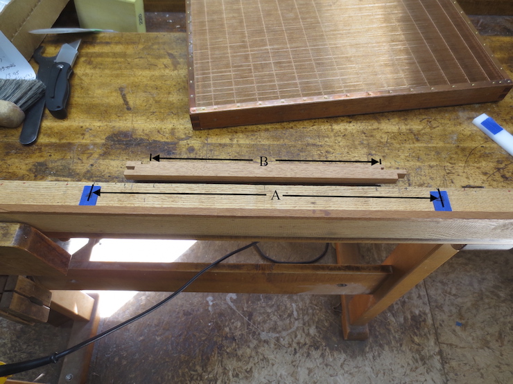
Unfortunately I didn’t take the photo I should have so this one will have to suffice. Part “B” is actually one of the short sides of the deckle; imagine for now that it is 6 inches longer to fit the masking tape shims placed on the beam. “A” is the ‘functional length’ of the long (near and far) sides of the deckle that we are actually working on for this first step.
The shims are layers of masking tape. There are currently 4 layers in place for this 12″ x 18″ deckle. A smaller deckle would use fewer shims; a larger deckle more. The shims are centered about 1-1/4″ from each end of the deckle part.
The same at the other end.
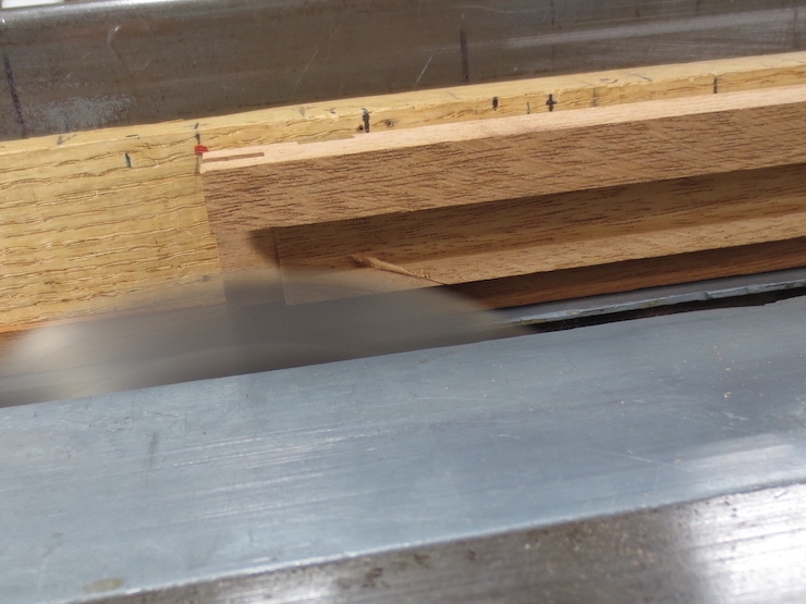
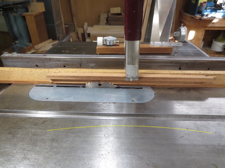
After the part has been placed on the beam and clamped a test cut is made. Here you can see a very light cut being started. I’ll finish the cut and then take the part off the beam to check to see if the curve is ‘strong enough’. Another layer of masking tape can be added to accentuate the curve or a layer removed to reduce the curve.
The exaggerated yellow line shows which way the part is being bent against the beam during the saw cut.
One more view.
Creating Concave Curves on the Short Sides
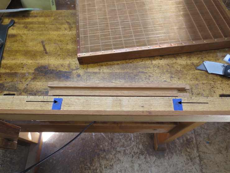
After the long sides have been finished the first step towards cutting the concave curves along the short sides is moving the shims. The same ‘stacks’ of shims are used again but they must be peeled off and moved inward to accommodate the shorter length of these deckle parts. Using the same shims at the ends means you don’t have to reset the table saw fence to make the parts align where they meet at the corners. The arrows show how the stacks have been moved.
Shims are now added to the center to create a ‘hump’ to bend the part over. Remember that this part needs to be bent the opposite way.
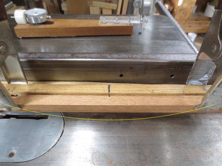
The part is clamped at both ends to bend it over the ‘hump’ in the middle. Once again the exaggerated yellow line indicates the curve that the part is given while it is sawn.
I started out with 6 layers of tape in the middle. After deciding that the curve needed a little more ‘oomph’ I added one more layer, making 7 total. Since there are 4 layers at each end the net ‘displacement’ in the middle is 3 layers of shims (about .012-.015″). About 1/64″
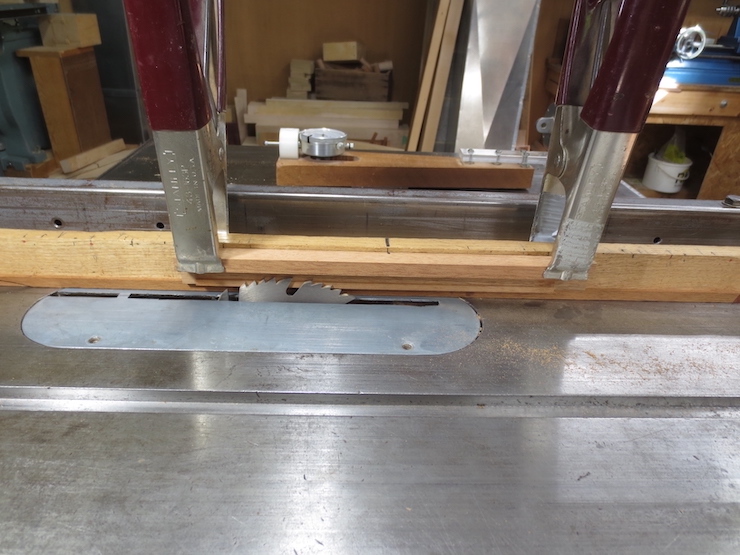
Just another view of how the part is trimmed on the table saw.
The tape shims were visible in this photo but just barely. I’ve accentuated the color to show how they are placed. The stack of shims actually extends all the way down to the ledge to support the entire width of the deckle part, though it doesn’t appear that way in the ‘doctored’ photo.
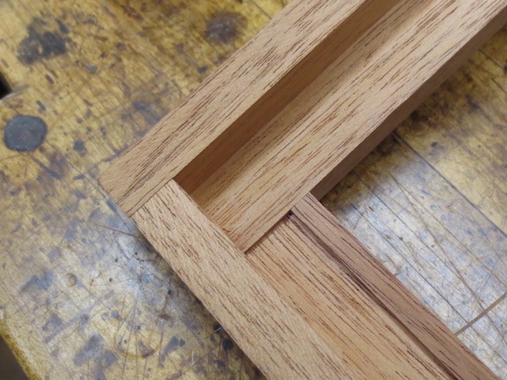
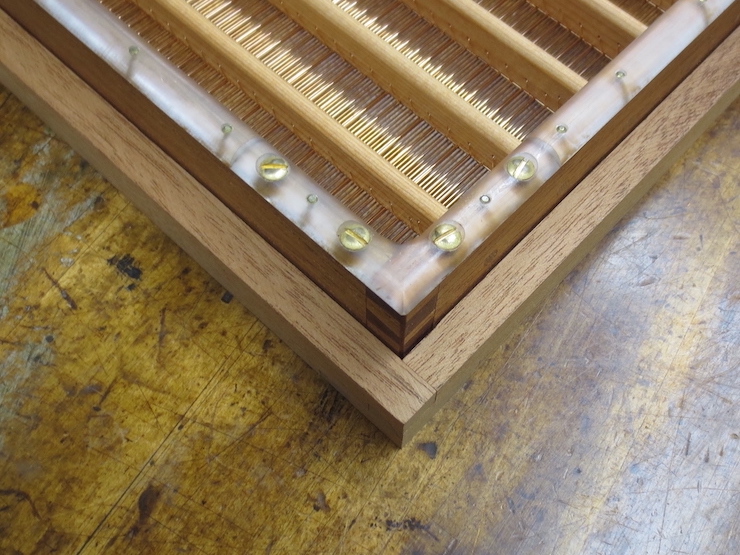
When the parts are assembled the convex and concave edges should meet perfectly at the inner corners of the deckle.
Now the deckle is ready for the joints to be glued.
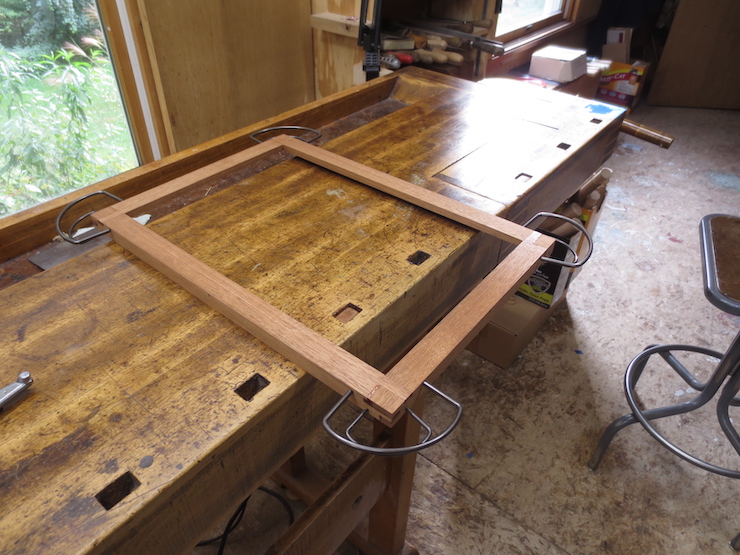
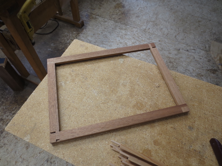
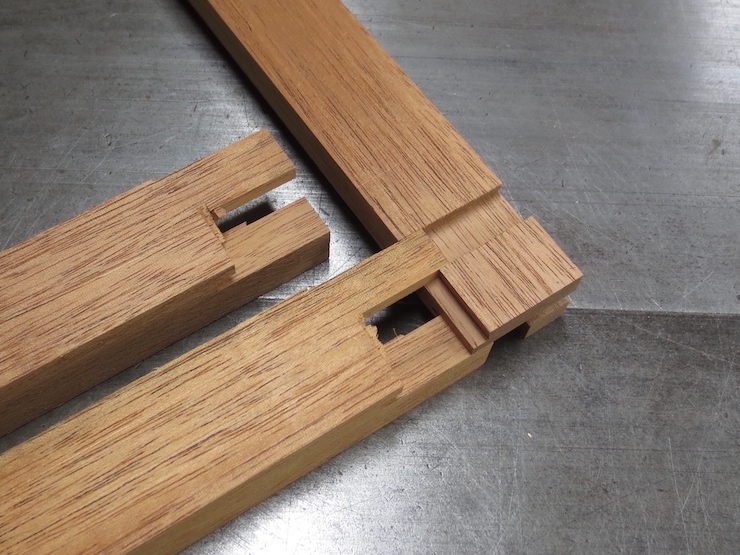
The joints have been finished and now the four parts can be put together to form a rectangular ‘frame’. But the parts still need to be adjusted in a couple of ways to fit the mould before the joints are glued. In this post the the parts will be trimmed to create a small gap where the deckle laps over the sides of the mould. In the next post the inner rim of the deckle will be shaped in a special way to fit snugly against the wire face of the mould.
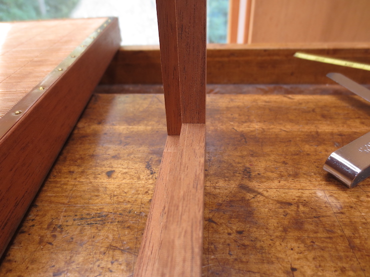
The arrow points to a gap where the outside edge of the deckle laps over the mould on all four sides. Making it the right width is the focus of this post.
To start the process the deckle parts are fitted together with two opposite corners left loose.
When the assembled deckle parts are pushed tight against the sides of the mould the joints of those two corners are unable to close completely. This is because the overlapping sides of the deckle have been (intentionally) left too thick. If you measure the gap left in the joints you can determine how much needs to be trimmed off. As a first step I cut away just enough that the deckle can fit over the mould with the joints fully closed.
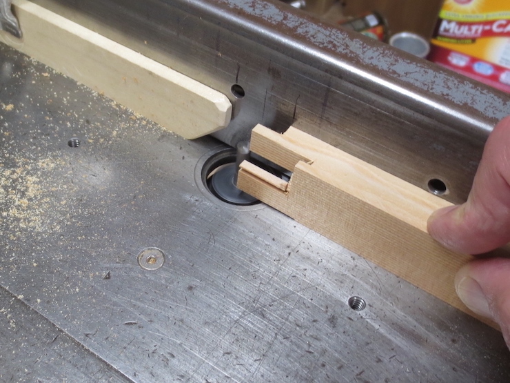
A router is set to nearly reach the bottom of the deckle groove and the table saw fence is set to make this preliminary cut.
The process seen from a different angle.
One part has been pushed all the way through. All four deckle parts are trimmed the same way before putting them back together.
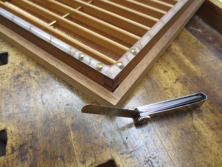
Now the joints can close completely but the gap between the sides of the mould and the inside edges of the deckle is still too narrow. It can be measured using a shim set.
Using that measurement the table saw fence (which has been left just as it was) can be moved to cut away a little more. I shoot for a total gap of about .025″. (This when the deckle is pushed up tight against the mould on two sides; it is approximately half of that if evenly divided among the sides). This is not a super critical dimension and is most likely tighter than it needs to be. The deckle should not get stuck on the mould when the wood swells but the fit should not be sloppy either.
The routed cut has been interrupted to show what it looks like. It is important to avoid letting the router bit damage the inner surface of the lap tenon which is in nearly the same plane.
This is what the finished gap looks like. It is usually necessary to trim a little more off either the long sides or the short sides to make the gap the same both ways.
In the next post the inner rim of the deckle will be given subtle curves to insure a tight seal when the deckle is pressed against the wires of the mould.
This is the last of four posts describing this way of shaping a traditional deckle joint.
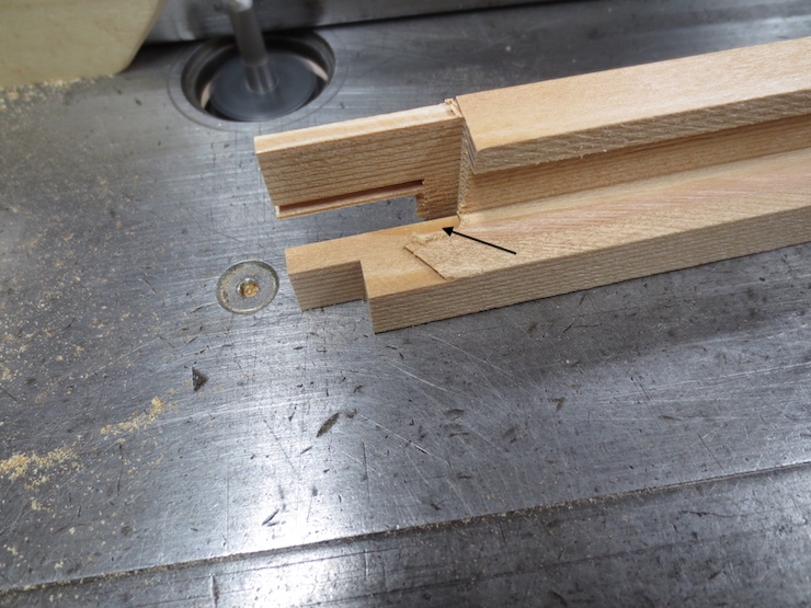
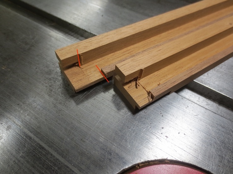
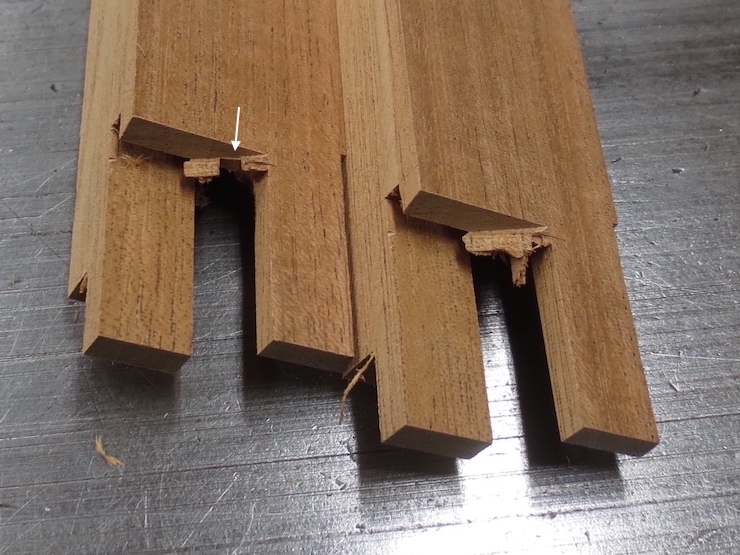
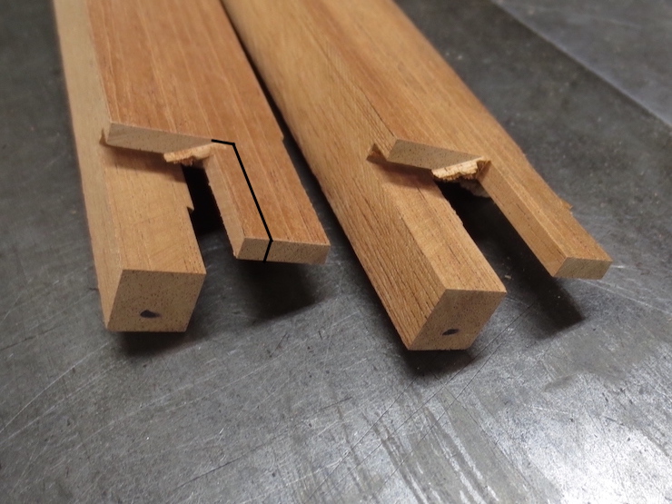
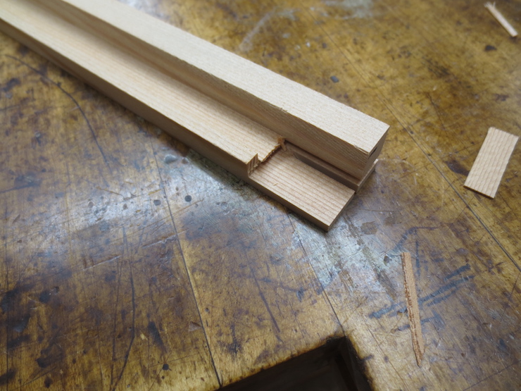
At the end of the previous post we left the joint at the stage shown at the back. Cutting away the part labeled “A” has made it possible for both tenons to slide partway into the joint but the end of the lower tenon (marked “B”) will bump against another part before the joint can close very far. The two white arrows show where this will happen. Cutting away the area marked “B” will let these parts lap over each other to enable the joint to close farther.
The piece at the left has received a saw cut, the first step in removing ‘area B’ (above). A line has been scribed with a marking knife to reduce chip out.
A cross cut finishes this part of the joint so it can lap over the other half.
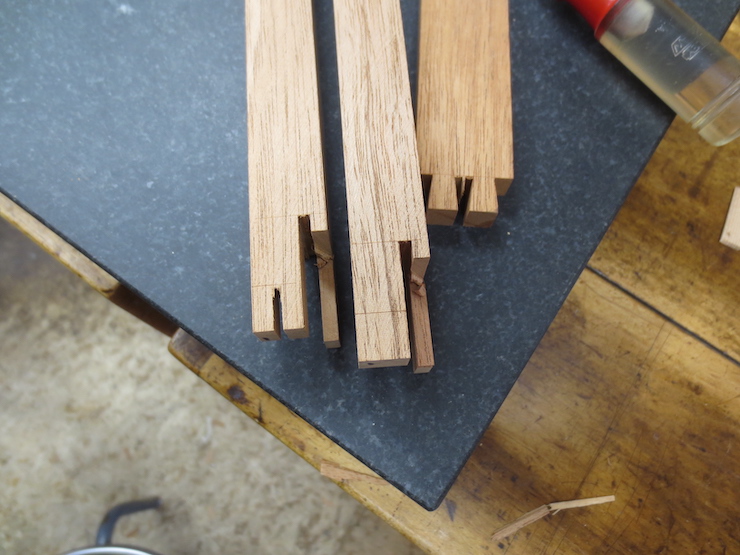
The parts on the left have completed lap joints; at the right the cross cuts haven’t been made.
The following five illustrations show unnecessary steps. The updates are indicated below in boldface along with three more illustrations of a better method.
This step routes away the next area that needs to be removed.
After the cut it looks like this. If not removed, this area would be the next hindrance to closing the joint; the next place the parts would ‘bump’. Note: routing away the deckle rim ahead of time or merely chiseling away one corner makes the cut shown by the arrow unnecessary. (See photos at end of post)
The radius left by the router is chiseled square (at the arrow).
Next the shoulder is widened on the underside of the dovetail tenon. When finished (as shown in front) it lines up with previous cuts made across the deckle rim and at the slanted side of the tenon. You may recall that these were both cut to the exact width of the deckle pieces. The line and arrow show where the part in the back still needs to be trimmed. Note: Altering the joint a bit to put the bottom of the deckle groove in the same plane as the slot eliminates the need to trim this waste.
This is how this cut is made.
Photo updates: (There is always more to learn).
For this batch of deckles the joint has been altered to put the top of the slot at the same plane as the bottom of the groove that runs around the inside of the finished deckle. In the photo above the deckle rim on the left has been cut back to its final shape. Doing this step now rather than latermakes the previous steps unnecessary.
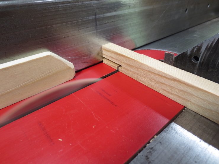
The set-up for routing away the waste part of the deckle rim.
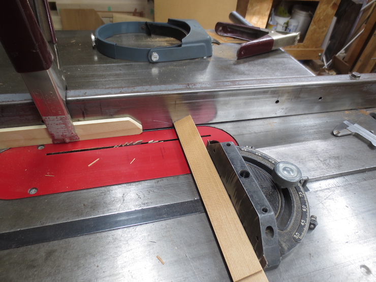
The saw blade is tilted 9 degrees for the next cut.
This allows the part to be cross cut at a 9 degree slant. The black arrow indicates the finished cut.
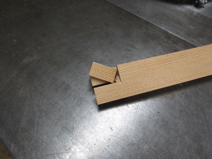
This shows how this slanted ‘dovetail’ face fits with the other side.
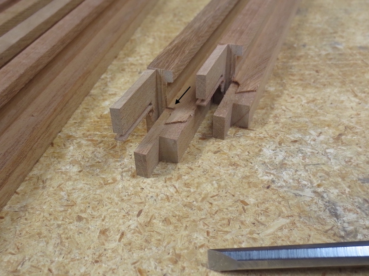
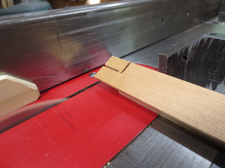
For this batch I made one more small cut from the bottom. This was not truly necessary but made it easier to chisel away the waste. Below the arrow you can see the routed area extending down into the waste.
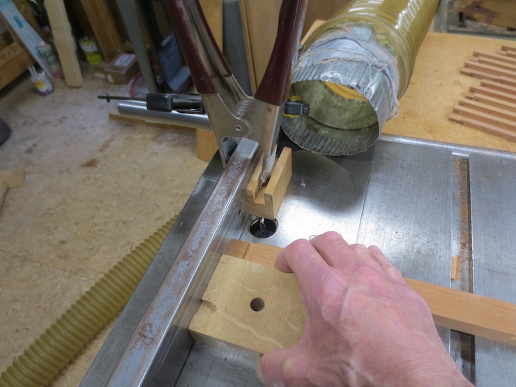
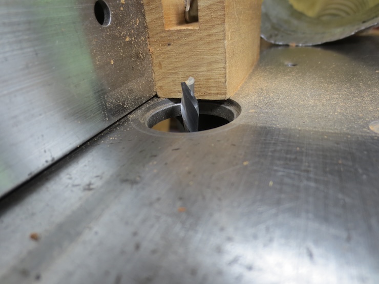
This is the set up used to route away the area shown below by the arrow.
The same cut seen from the other side.
The uncut portion in the corner is pared away from both directions until the cuts meet and the waste falls away.
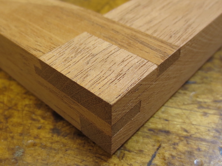
The joint is finished!
The parts of the joint now fit nicely together but several more steps remain to complete the deckle.
Edits to this post:
Chiseling away the corner makes routing a groove unnecessary.
After final trim the bottom of the deckle groove will be an extension of this surface of the joint.
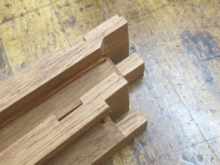
The end of the last post left us with two tenons ready to be fitted into spaces left in the other half of the deckle joint. Both tenons were cut to the correct thickness and now both need to be trimmed to width.
The simpler lower tenon is the first to be fitted. It only needs trimming on one side. The finished width is indicated by the black arrow.
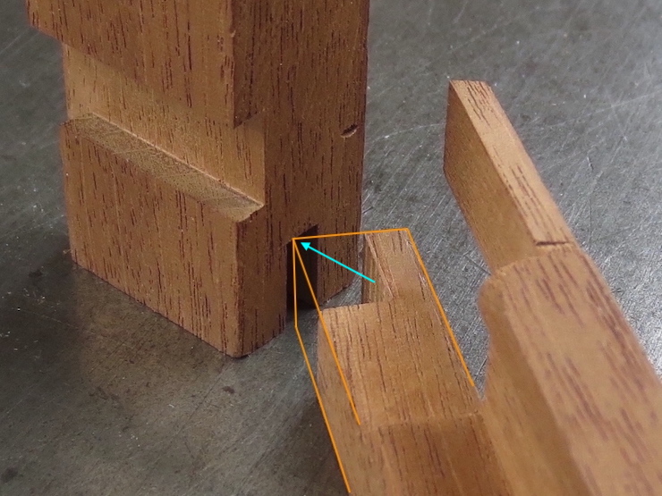
This is a view of how the width is tested. The corner indicated by the arrow should slide into the opening in the other piece. Since I neglected to photograph this step the orange lines have been added to show what the part would have looked like.
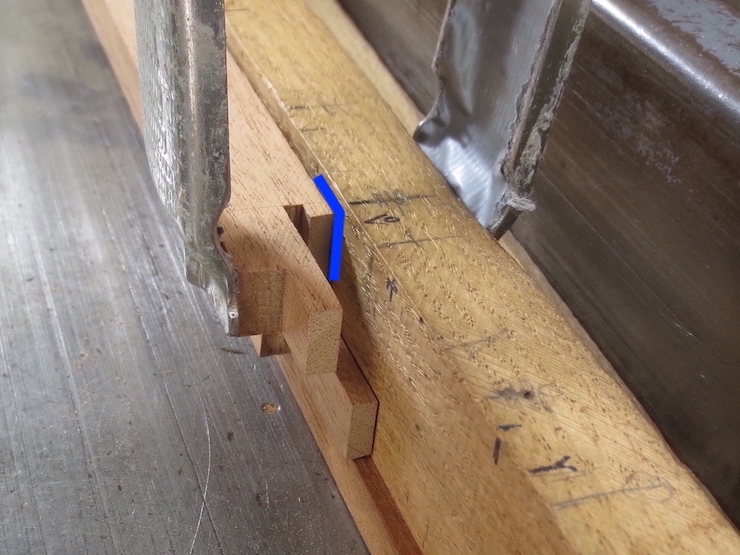
This photo shows how the width of the tenon must be sized to fit alongside a narrow edge in the other part of the joint. Again, the orange lines show how the part would have looked. The arrow points to the bottom corner of the inner vertical surface being fitted (hidden in the photo). The blue lines show how the other part would have looked at this stage. In practice the fit would be tested with the part on the left standing on end and both pieces resting on the flat surface. (This was difficult to photograph).
Here the fence of the table saw is set to trim the proper width and a stop keeps the cut from going too far. One part has been left un-sawn to show what the cut looks like. Fitting this tenon first allows the lap joint parts to slide past each other so the more complicated sliding dovetail part can also be tested, trimmed and fitted. If left untrimmed the lap joint would block the sliding dovetail from ‘starting’ in its groove (which is essential for testing its fit).
A very small cross cut is now made to establish the shoulder of the sliding dovetail tenon. It should line up perfectly with the previous finish cut across the deckle rim. (In the photo the fence still needs to be adjusted to make the cut a little further to the left). The saw blade is set to barely protrude from the top of the table saw and a ‘stop’ is used. The blade setting and the position of the stop must be ‘fiddled with’ more than usual to get the adjustments right before giving all of the deckle parts these tiny cuts.
The shoulder now lines up perfectly so the sliding dovetail will be able to reach full depth in the groove after its sides have been trimmed.
The right angle block is canted 9 degrees by a special block screwed to one end. This enables the side of the tenon to be sawed to match the angled face of the dovetail groove.
The part on the left has had its 9 degree angled face sawn; the part on the right has not yet been trimmed.
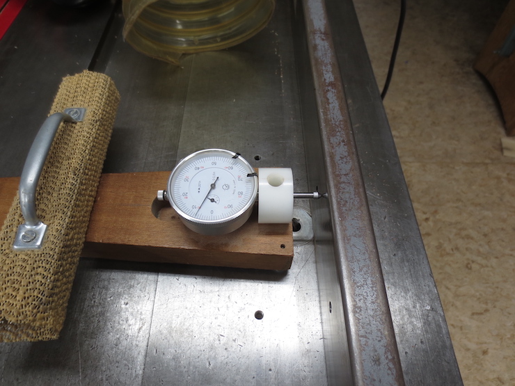
As a first step the slanted edge of the dovetail tenon has been left a little ‘fat’. This photo shows a way to determine how much more needs to be cut away. The fit turns out to be good when the previously cut half of the joint is elevated on a .005″ shim (this has been determined by trial and error, the shims being in .001″ increments). This means that .005″ more needs to be trimmed off of the slanted side of the tenon. With the help of the dial indicator fixture the table saw fence can be moved precisely this amount to re-saw the part and correct the cut.
When all parts are trimmed a chisel easily removes the little bits that are left at the shoulders.
The slanted face has been correctly fitted and now the tenon needs to be cut to width so it can slide into the groove. The black lines show the part that needs to be cut away. The piece on the right has already been trimmed.
Using the dial indicator to adjust the table saw fence, the width of the tenon is reduced in small increments until the test part slides nicely into the half dovetail groove. Then all of the parts are trimmed the same. Before the joint can close completely a few other areas must be trimmed away. This will be described in the next post.
The next three posts will show how the other half of the deckle joint is made. This half of the joint takes longer so the process is broken into segments.
One side of a saw cut establishes the bottom surface of the sliding dovetail; making it the right thickness to slide into the dovetail groove. The same saw cut starts a slot to fit a tongue that has already been made. Since both tongue and slot are the full width of the deckle, a deckle part can be used as a gauge when scribing the part (above) to prevent ‘chip out’ when the saw exits the cut.
Here is how this slot is cut using the right angle block.
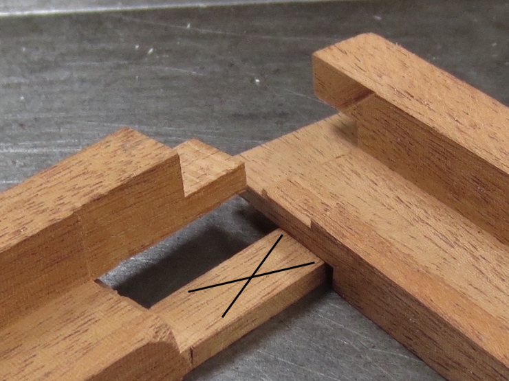
Some waste can be sawn or chiseled away after removing the test part from the saw. The black line shows the imaginary saw cut and the waste is marked by the yellow “X”. Removing this bit of waste (only on the test piece) makes it possible to test the end of the dovetail tenon against the slot it must fit into. (See photos at bottom of post).
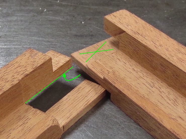
The thickness of the sliding dovetail (indicated by the black arrow) can now be tested and trimmed to fit the groove. The first cut leaves it slightly thick on purpose. In one or more tries, the table saw fence is reset (with the help of the dial indicator fixture) to improve the fit of the scrap test part. When the fit is good all of the deckle parts are cut the same, finishing this step. Next the slot must be widened (by moving the fence and making another saw cut or two) to fit the ‘tongue’ that was previously shaped on the other end of all the deckle pieces. The green line shows how the slot will be widened.
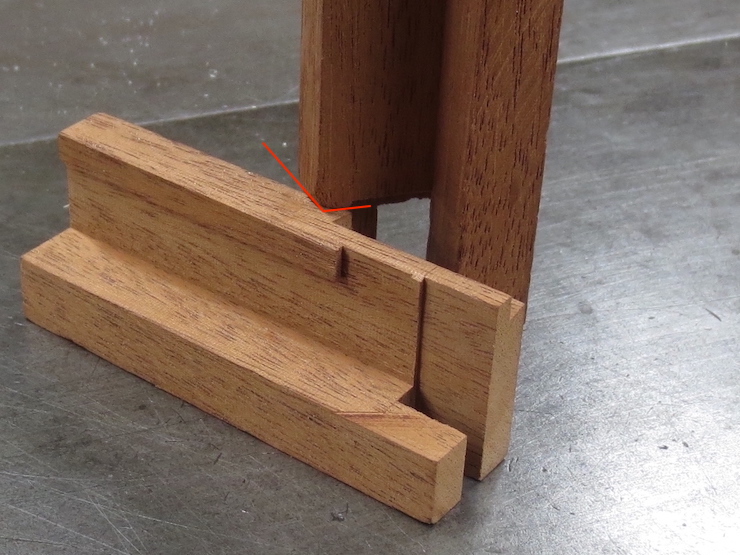
Next a small cut is made across the rim of the deckle. In the photo below the right end of the red arrow points to it.
The partly finished joint now looks like this. The dimension indicated by the black arrow is now exactly the same as the depth of the dovetail groove that was cut in the first half of the joint. The dimension indicated by the red arrow is the same as the width of the deckle parts. The slot shown by the green arrows has been widened to fit the previously shaped tongue on the opposite joint. Each of these finished surfaces have been tested against the appropriate parts of the other side of the joint. (The photos at the end of this post show how this is done).
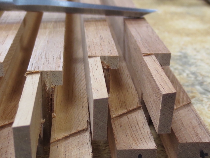
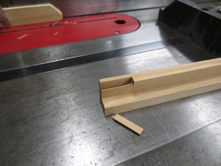
The next few steps rough out areas that need to be ‘cleared out’ to allow the dovetail tenon and lap tenon to be fitted more easily (in the next post). The first piece of waste can simply be broken off (above).
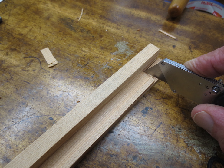
The next part can be cut off by hand with a utility knife. The shoulder near the tip of the knife will be trimmed to exact size later.
This cut is not exact either, but the first step in removing another waste area.
The same cut shown from below.
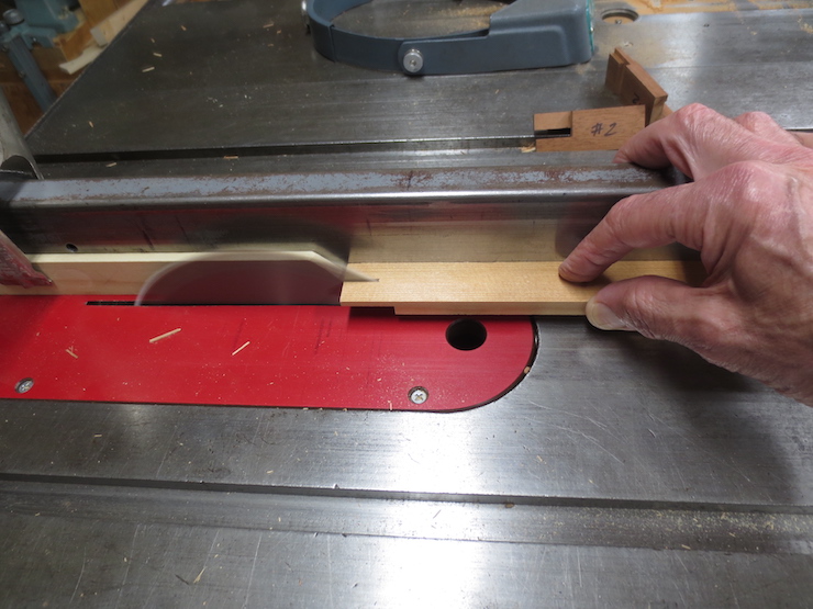
Another roughing cut is made. The height of the blade is set to cut across the waste without touching the ‘good’ part.
The two roughing cuts seen from above.
Now this part can be broken away on all of the pieces.
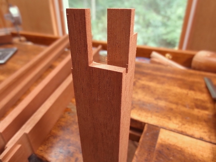
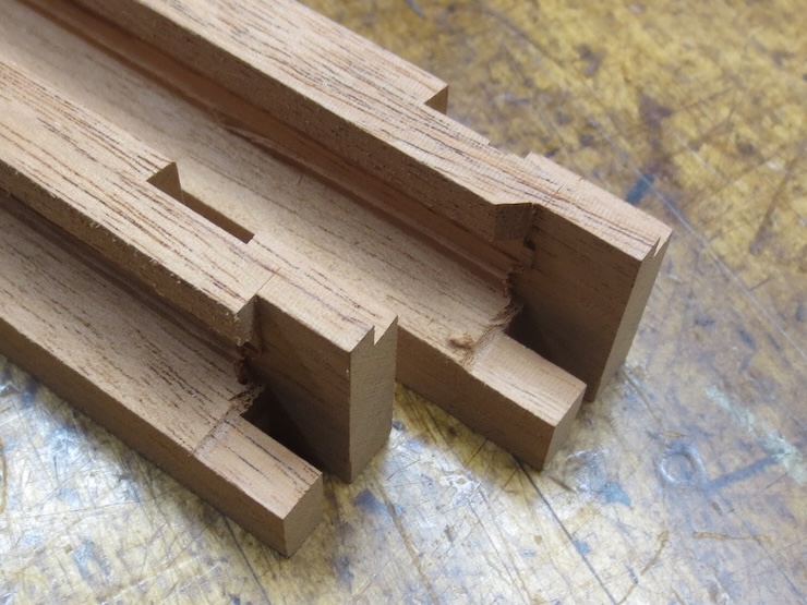
Removing the waste frees up the two tenons so they can be trimmed to fit into their corresponding groove and slot (covered in the following post). The sliding dovetail tenon (on top) is now the right thickness but needs to be trimmed on both sides. Parts of the lower tenon will be cut away to form a ‘tongue’ to fit into the slot prepared for it (see the previous post). Shaping this tongue creates a notch that will receive a lapping part, also shown in the previous post.
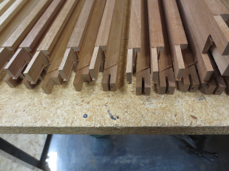
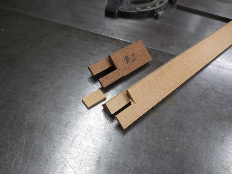
A completed example of the joint is shown for comparison above.
Testing the fit
As parts of the joint are shaped they are tested against the (previously finished) first half of the joint. The examples shown below have joints that have been completely shaped but serve to demonstrate the method.
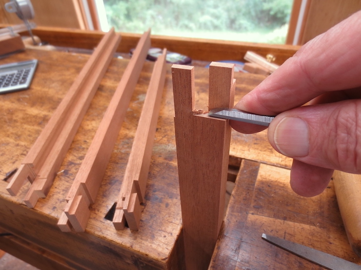
The thickness of the sliding dovetail tenon is tested against the groove it must fit. If the parts are held firmly against a flat surface the mating surfaces should be able to slide past each other with little resistance. The surface that is being adjusted is indicated by the black “X”.
Likewise the other side of the slot can be tested against its mating surface. The green arrow points at the (hidden) surface that is being trimmed to fit against the surface indicated by the green “X”.
The cut across the rim of the deckle can be tested by standing the test piece on end. The red lines indicate the surface that is being trimmed to fit.