The larger structures and functions of this loom have been described in the last six posts. Some small but essential parts have not received much attention and these are more fully explained here.
Spindles and Spindle Drive Weights

Spindles
A spindle is required for each pair of chain wires so a lot of them are needed to produce a large facing. The most tightly spaced spindle rack has spaces for 43 spindles, that’s the most that could ever be needed for this loom.

The spindles are made of 5/8″ diameter acetal plastic rod. They are 7/8″ long.
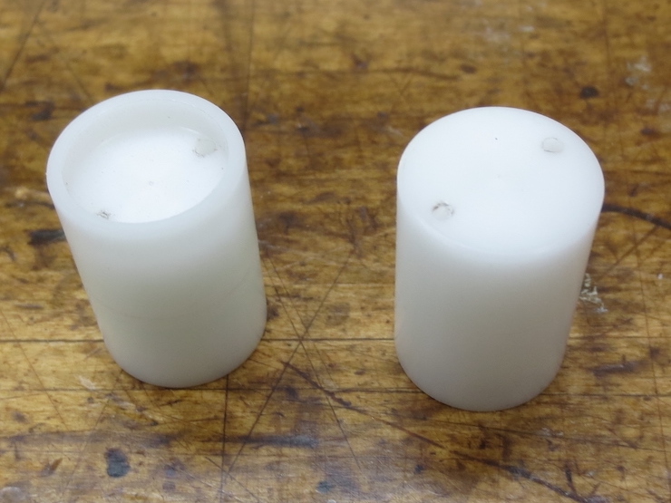
Each spindle has a flat end and a one that is recessed 1/8″. The spindles are placed with flat ends up when making laid facings. This splays the chain wires at a wide angle to twist the chain wire tightly. The spindles are turned over with recessed ends upward when making backing wire. This causes the wires to be splayed less widely to help create the wider spaces between backing laid wires. This is not strictly necessary but gives a better looking result with the twists being more even.
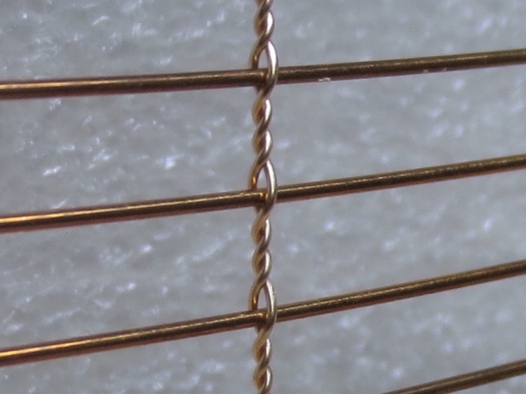
Above, the twists are more symmetrical if the recessed spindles are used. (Laid backing made with .0254″ laid wires and .0150″ chain wires.)
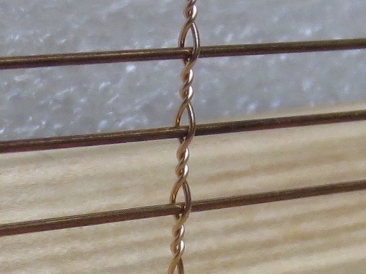
Here with the spindles’ flat side up the twists are tighter and the twisting less symmetrical. The ‘eyes’ are larger and don’t grip the laid wire as tightly.
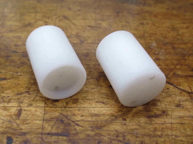
The holes for the wire are 1/16″ diameter and are spaced 7/16″ on center.
Spindle Drive Weights
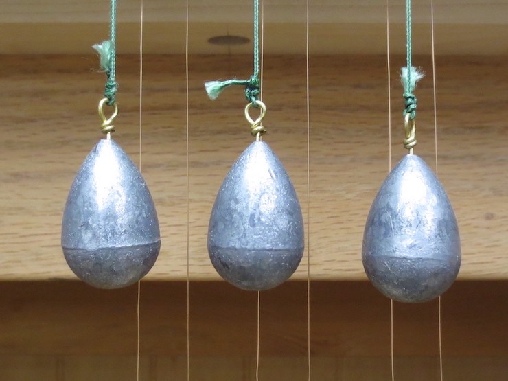
A drive weight is needed for every spindle so a lot of these are needed too.
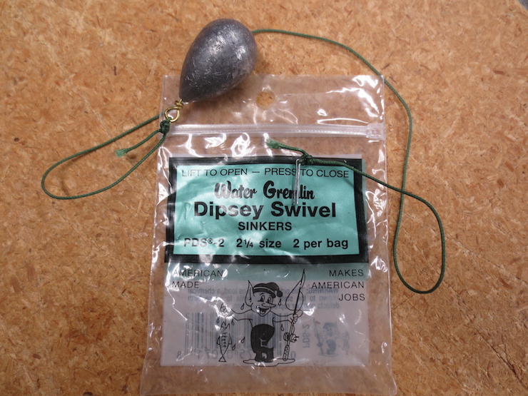
The ones that are used weigh 2.2 ounces. The next smaller size (1.75 ounce) didn’t work well.
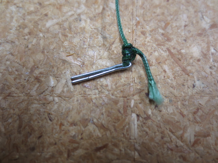
All of the drive weights have a length of braided fishing line attached. The 14″ length used here isn’t critical but all should be the same so the weights will line up evenly along the front of the loom. Each knot is fixed with a drop of cyanoacrylate glue. As shown in this photo the free end is tied to a cotter pin. The pins are altered a bit; they’re clipped short and the eyelets smashed shut with vise grip pliers so they don’t stick out as far when inserted into the attachment holes in the cord reel.

The cotter pins start out like this. Plain wire can work but the half round wire of cotter pins is ideal.
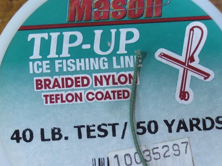
This fishing line works well. The cord should be flexible and soft so it can flatten to grip the sides of the spindles.
Wire Spacers, Wire Slides and Weights

Below the spindles and drive weights are the wire spacers, wire slides and wire weights. The foam board wire spacers hold the wires apart to prevent them from twisting around each other. The wooden wire slides also have this function but are made for their lengths to be adjustable. A couple of inches of free, bare wire needs to be maintained just below the twisting mechanism. The adjustable wire slides make it possible to keep this space from being too big or too small as the wire spacers are removed a row at a time. The bottom bars of the slides also serve as attachment points between the chain wires and the weights.
Wire Spacers
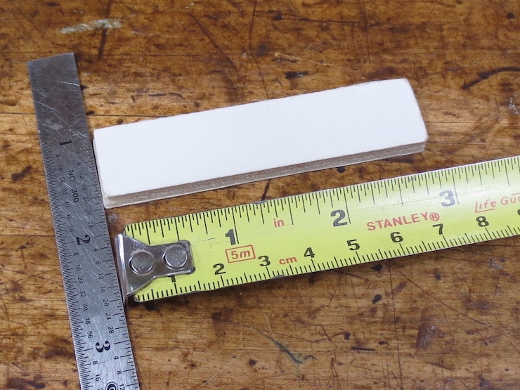
These are just pieces of foam board, 3/4″ wide and 3″ long.
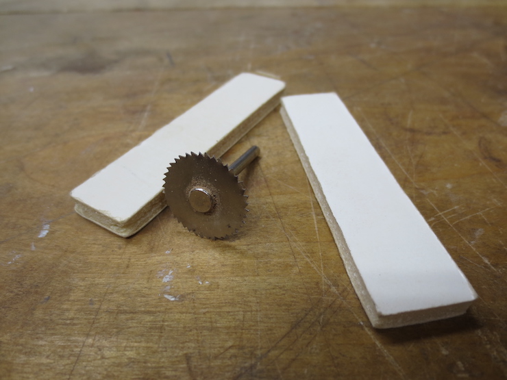
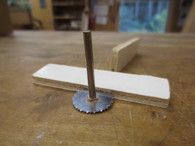
This little saw was chucked into a drill press and a fence was clamped to the table to cut slots into the sides of the spacers. The slots are just deep enough to match the spacing of the holes in the spindles, 7/16″.
Hundreds of these are needed, as many as a dozen for each pair of chain wires for the very largest facings. If you don’t accidentally step on them they last a long time. I made a box of these 40 years ago and haven’t needed to make more since.
Wire Slides
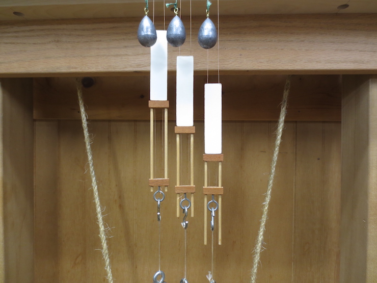
This photo shows the adjustable function of the wire slides. The wire slides also serve to attach the chain wires to the weights. The ends of the chain wire are twisted together below the lower cross piece next to the little screw eyes.
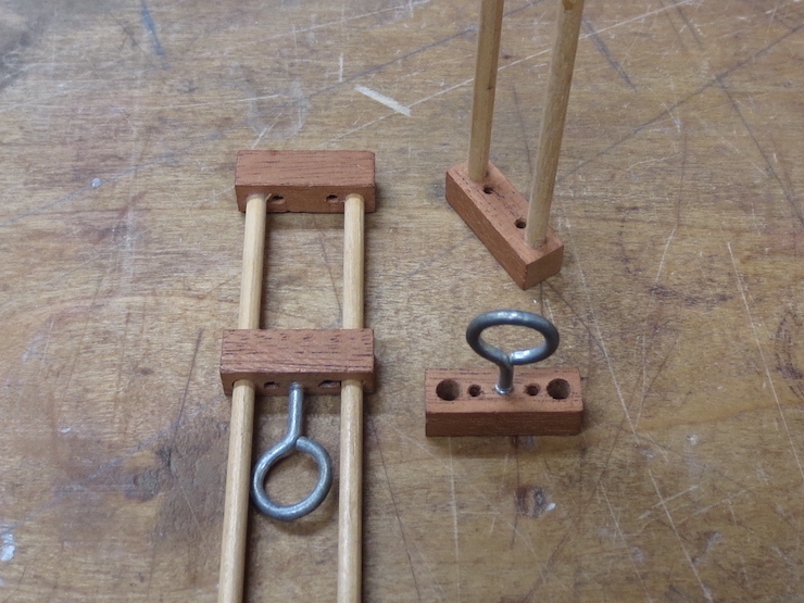
The small holes are spaced a little closer than the holes in the spindles (a little less than 3/8″ apart). This way when the top bar of the slide is pushed up against a foam board spacer a slight binding action is created. This helps hold the two parts in place on the wires.

The 1/8″ diameter dowels are glued into the upper part of the slide. These wire slides also need to be made in quantity; one for each spindle.
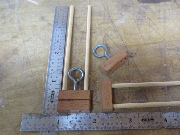
The slides are 4″ long and 7/8″ wide and can adjust about 3″. The length of the crossbars limits the minimum chain spacing for this loom to just over 7/8″; any closer and the parts would bump into each other as they turn. A 15/16″ chain wire spacing can be made with no problems. Making anything smaller would require some research and a whole new set of parts; smaller spindles, spacers and slides.
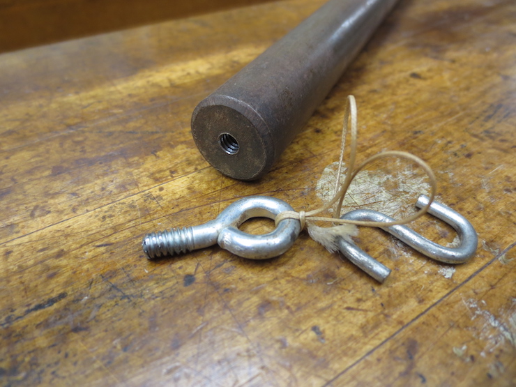
Wire Weights
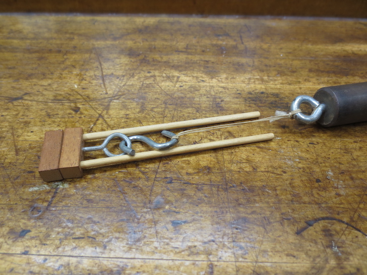
The weights attach to the slides like this. The cord attached to the weight should be long enough that the dowels can’t reach the weight when the slide is fully closed.
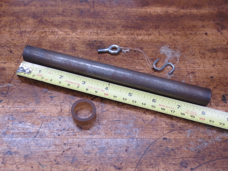
These weights are 3/4″ diameter steel rods 8″ long. They hold the chain wires under tension as they are twisted into place. These one pound weights work well for all sizes of wire from .008″ to .015″.
The weights need to hang from cords so they can spin freely. When the spindles turn the motion is carried down the wires to the weights. These develop momentum (like flywheels) so they turn a little too far before starting to spin back. While a facing is being made the weights continuously oscillate at the bottom ends of the wires. The length of flexible cord mostly isolates this action to the weights so it doesn’t interfere with the wire twisting action happening above.
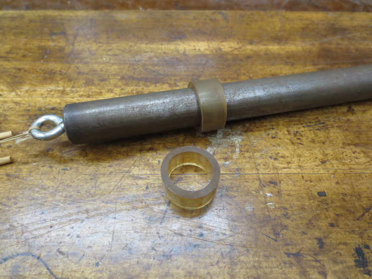
Unfortunately these weights turned out to be slightly magnetic. Sometimes it is necessary to slide a little piece of hose over a weight to keep it from sticking to the one next to it.
