Most of this information is good for understanding the way this loom works. But you should look at posts #63 and #64 for recent improvements in the loom design which make many things here obsolete.

This is a self contained mechanism that is fastened to the front of the traveling beam of the loom. The spindle rack is the base of the twisting mechanism; all the other parts are attached to it. It is made from a single piece of wood, as long as the longest laid wire. It has 5/8″ holes bored through it at regular intervals to hold the spindles. A cord reel passes from end to end. It is attached by end plates to the spindle rack. A crank is affixed to the right-hand end. The crank’s back and forth rotation is limited to about 180 degrees, between the fixed stop and the adjustable stop. This hand powered crank supplies the effort to turn as many spindles as are required to make any size facing or backing. A drive weight and cord are hooked up for each spindle used. The back end of each cord is fixed in the cord reel and the front is tied to a 2.2 oz. lead weight. Each cord wraps three times around a spindle to turn it by friction. When the crank is rotated back and up it ‘reels in’ the cords causing all of the weighted spindles to turn clock-wise simultaneously. This allows all of the chain wires to be twisted at the same time. This simple cord/spindle mechanism has a couple of important qualities that I will attempt to describe in the following text, photos and videos.
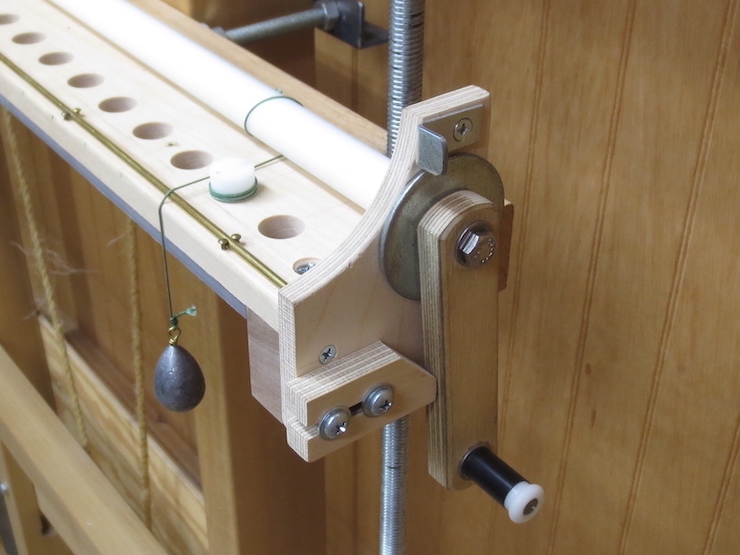
Spindles are normally placed in the center of the spindle rack when a wire facing is being made. For these photos a single spindle has been hooked up near the crank so most of the working parts can be shown together. The wire trough has been removed to reveal the spindle, weight and cord.
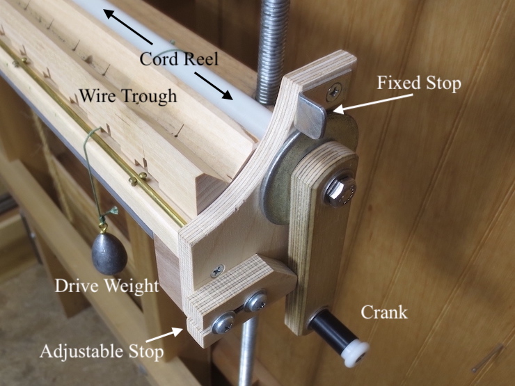
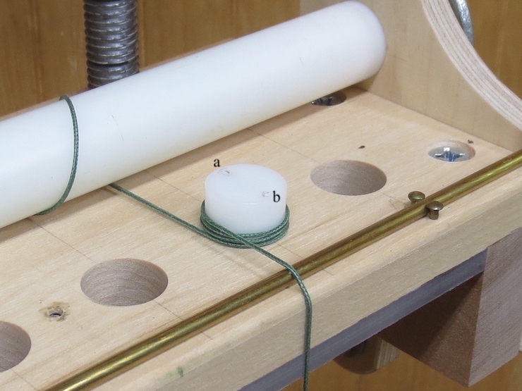
Some of the parts are identified here.
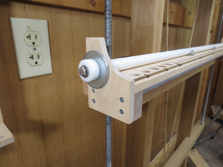
The left hand end of the mechanism showing the plywood end plate, and a washer, cap and machine screw that hold this end of the cord reel in place.
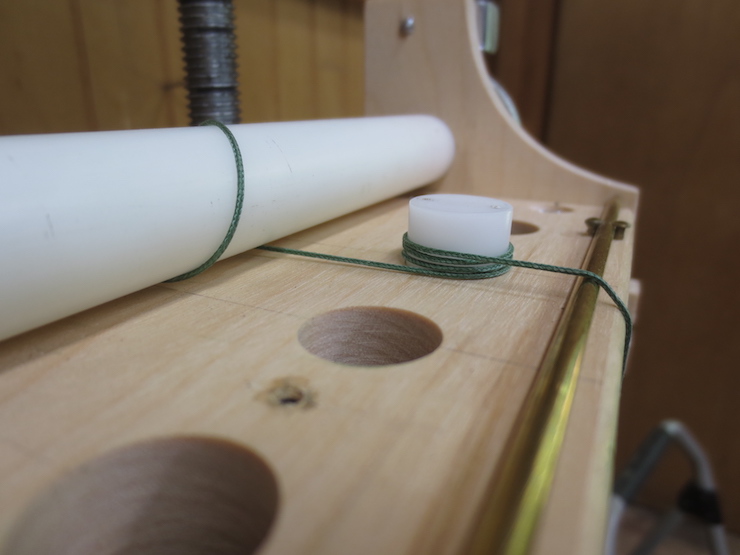
A spindle is rigged by wrapping a cord three times around it. The 1/8″ brass rod at the front of the spindle rack holds the front of the cord up to keep the loops from crossing over each other.
Understanding How it Works
The crank is limited to turn (back and forth) about 180 degrees. The reel is a larger diameter than the spindles so the spindles end up turning a little MORE than 180 degrees. This is important and will be explained later. As you can see above when the spindles have no load on them they will simply turn back and forth with the crank.
A repeat of the first video showing an unloaded spindle turning back and forth.
I am placing gentle pressure on the side of the spindle with my finger. Under load the spindles turn clock-wise and do not ‘back up’. This is the first ‘beauty’ of this simple mechanism; a simple back-and forth motion of a crank can be converted to a ‘one way’ rotation of the spindles. This allows wires to be twisted in one direction to form chain wires. But if you look closely you can see that the spindles gain a few degrees with each rotation of the crank.
These extra few degrees of rotation are intentional and the stops of the crank are set to provide it. This video attempts to show the constant ‘re-calibration’ of all of the spindles (the second beautiful thing about this simple string and weight arrangement) that happens when a facing is being made on the loom. I am using my finger to simulate the stopping action usually provided by the pairs of (as yet untwisted) chain wires being raised (by the treadle and lifting mechanism) to engage the slots in the wire trough. (If the trough were in place you wouldn’t be able to see anything. ) My finger is allowing the holes in the spindle to re-align each time the crank is released, clumsily simulating the regulating action that is normally provided by the lift mechanism.
Repeating Cycle of Twisting Mechanism Only (other actions of the loom not included here)
(1) At Rest
The crank is ‘parked’ against the lower stop and the weight has dropped as far as the cord will allow; the resting position for the entire mechanism. The pair of spindle holes are oriented front and back with hole “a” in back.
(2) Crank Reels In
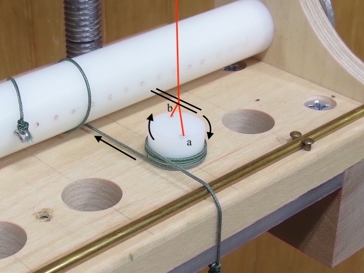
The crank has been rotated up to the fixed stop (and held there), reeling in the cord and causing the spindle to rotate a little more than 1/2 turn. Hole “a” has moved around to the front. The holes are not aligned directly front to back, having rotated past the center line. I’ve added imaginary chain wire here (red) and an imaginary wire trough slot whose sides are described with the parallel black lines.
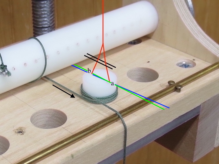
(3) Chain Wire Lifted into Slot

The crank is still being held against the upper stop so the rotation of the spindles continues to be ‘frozen’. However the loom treadle has been stepped on, lifting the upside down “Y” up, engaging the splayed wires in the ‘slot’. The wires are bent sideways a little by the edges of the slot because the holes aren’t directly below. The blue line shows how far ahead the spindle has turned compared to the green line which is drawn straight across.
(4) Crank Returned to Lower Stop, Spindles Re-Calibrated
The operator’s foot remains on the treadle holding the wires up so they are still engaged in the slot. The crank is on its way back down to the lower stop thus unreeling the weighted cord. This causes the spindle to reverse by a limited amount. At a certain point the engaged wires prevent the spindle from turning further and the cord begins to slip. By the time the crank has been released completely to rest against the lower stop the spindle has re-calibrated (a tiny bit behind the center line which is OK). Each time this cycle is repeated all of the many spindles in use will automatically re-align. That way spindles don’t get behind or ahead and all are always ready for the next twist.
Two laid wires are being added here. One is already in place. If you watch the white wire spacers behind the weights you can see them reverse a little just as the weights drop down. This shows the spindles re-aligning.

…er, so the standing length of the wire is charged with its own torque that needs discharge before the next twist?
LikeLike
I think you are correct to note that when the wire is twisted it gets ‘charged with its own torque’ but the wire is soft and doesn’t push back very hard. More significant is that the weighted cords are able to drive the spindles clock-wise but are also able to slip back without unwinding the wire. The twisted wires ‘want’ to unwind a bit, and help somewhat to turn the spindles backwards as they re-calibrate, but that ‘reverse torque’ is restrained to only a few degrees of rotation by the two splayed wires being caught in the narrow slot. After the weighted cord slips back completely it holds the spindle tightly within the loops. Though the wire still has some stored up force it is nowhere near enough to turn the spindles backwards even when the wires are disengaged from the slot. It’s not even possible to turn the spindles backwards with two fingers; the cord loops just get tighter if you try to turn the spindle the wrong way. Not sure this explanation is helpful. The mechanism is very simple but it is not easy to explain in words. The torque doesn’t seem to accumulate in the wire as more twists are added. (Ie. the wire doesn’t seem to need ‘discharge’). The twists at the beginning and ending of a finished facing look and act the same.
LikeLike