Assembly of the Mechanism
Note: Parts of this post may have been rendered obsolete. See Post #63.
Examining the parts as they are put together may be one way to understand its workings.
I don’t usually assemble the parts on the loom as I will do for this post. Normally the various spindle racks (a different one is needed for every chain spacing) are pre-assembled except for certain parts that they all share. For instance there is only one cord reel and crank needed for this loom. There are enough spindles and drive weights to make the largest possible facing. When a facing or backing is made only the number of these actually needed are attached.
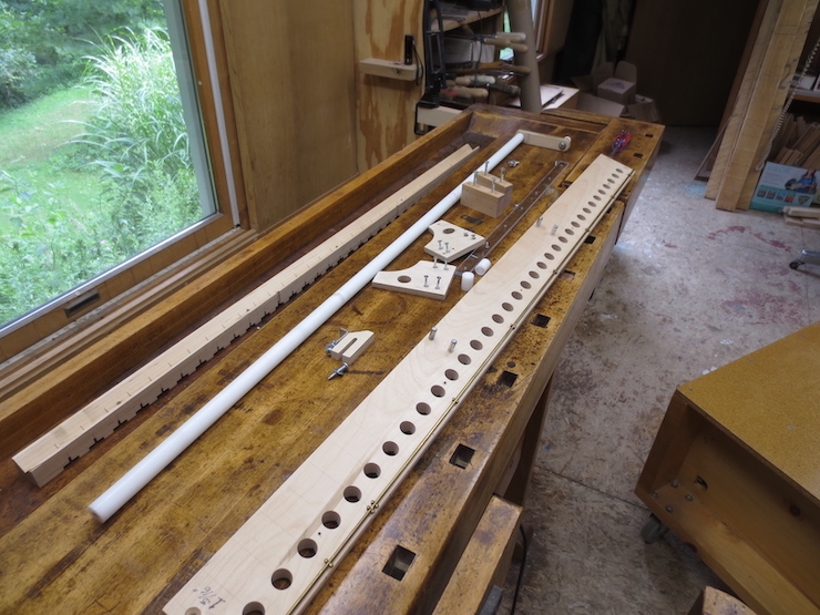
Spindle Rack
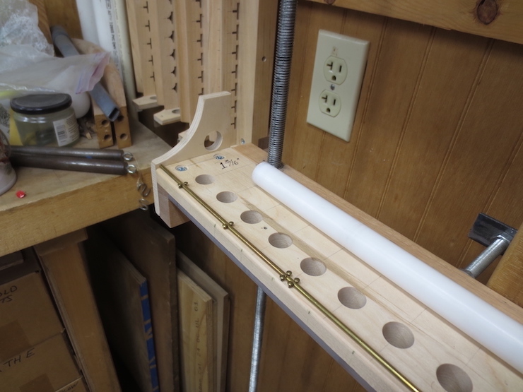
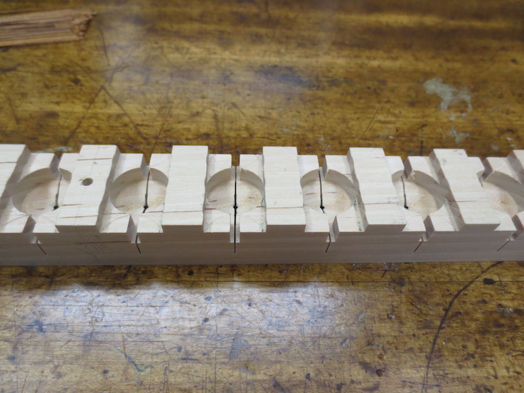
This spindle rack started out as a long piece of yellow birch with a simple rectangular cross-section (3″ wide by 1-1/8″ thick). These pieces should be the same length as the frame cross-pieces and the traveling beam, 42″ in this case. After the large spindle holes were bored two cuts were made on the table-saw to create the shape shown here. The thick back side provides support when screwed to the traveling beam; the front side is narrowed to 1/2″. This is the amount that the (7/8″ tall) spindles are set down into the rack.

A strip of polycarbonate screwed to the bottom prevents the spindles from dropping through the holes and provides a slippery surface for them to turn on. These holes were bored with a 5/8″ forstner bit and the spindles had to be turned down a bit on a lathe to turn freely. A simpler method is described at the end of the post.
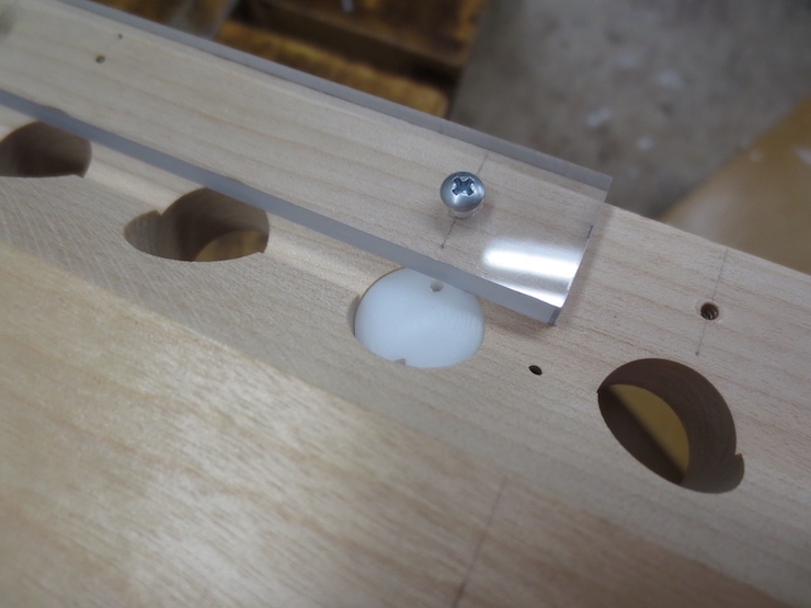
The strip overlaps the hole just enough to support the spindles without blocking the small holes through which the chain wire will pass.
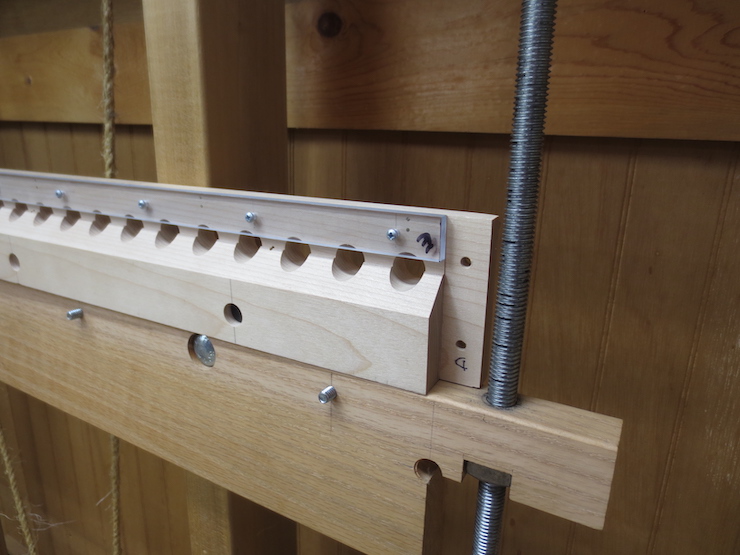
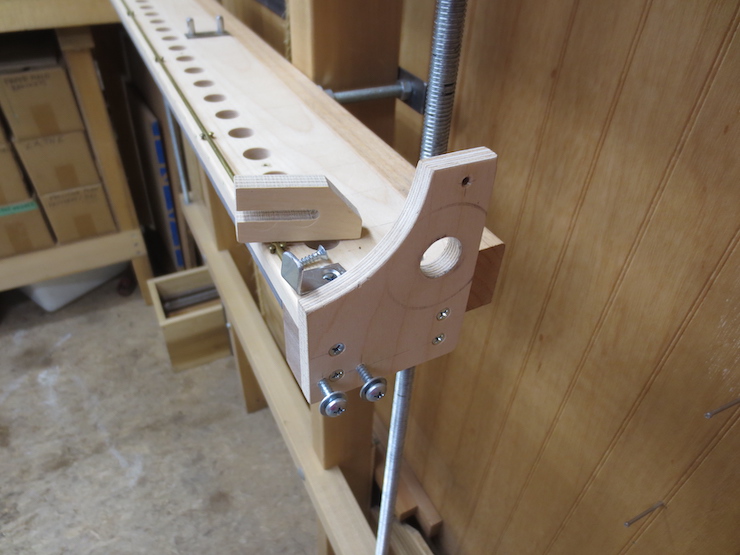
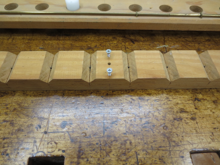
The partially completed spindle rack can now be fastened to the loom; specifically to the traveling beam of the indexing mechanism. The dark colored spot is one of five acetal ‘plugs’ sunk into holes. They are cross-drilled and tapped to receive the threads of the machine screws. Two of the five machine screws are visible here.
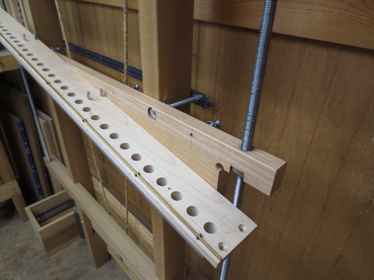
The rack has been attached at the center only.

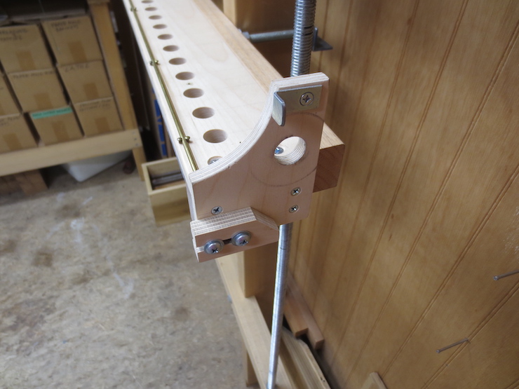
All five of the machine screws have been tightened to firmly attach the spindle rack to the traveling beam. Wood screws could also be used but would be difficult to drive from behind.
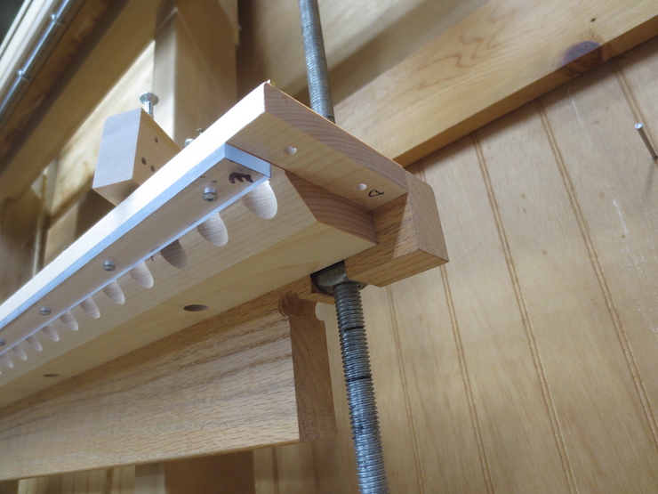
A view from beneath.
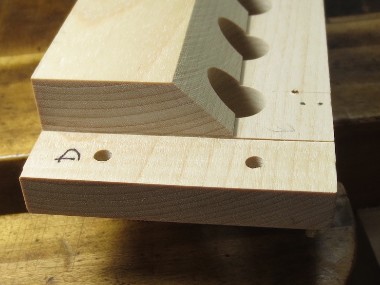
End Plates
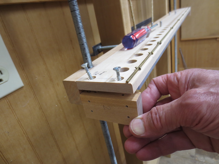
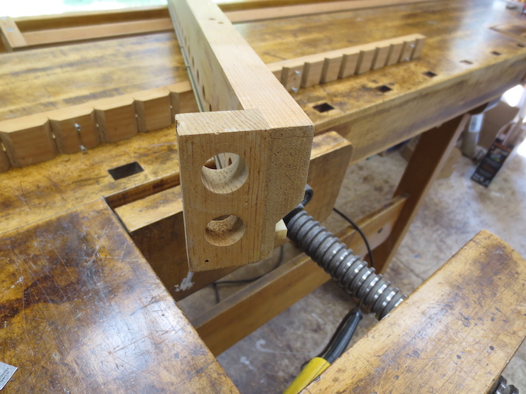
These blocks are screwed in place; one at each end.

They provide a way to fasten the end plates in place.
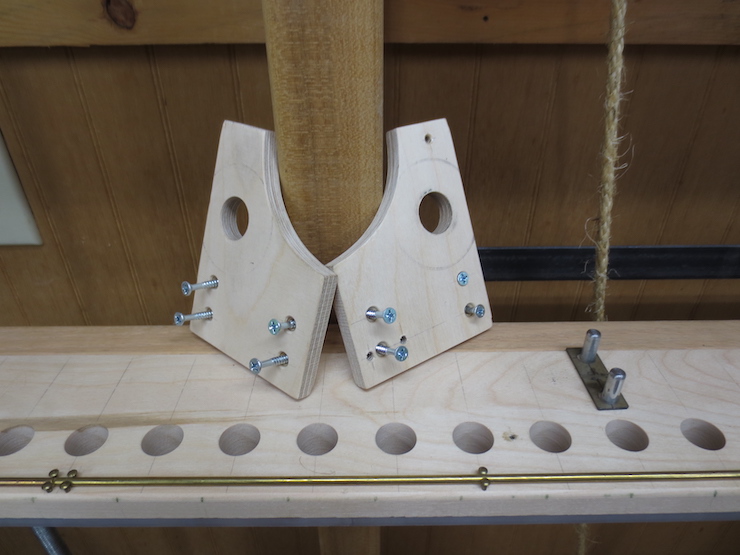
The end plates are mirrors of each other.
The right-hand end plate has a few extra holes for attaching the two stops.
These limit the motion of the crank to about 180 degrees (back and forth only). The top one is fixed and the bottom one is adjustable.
Cord Reel and Crank
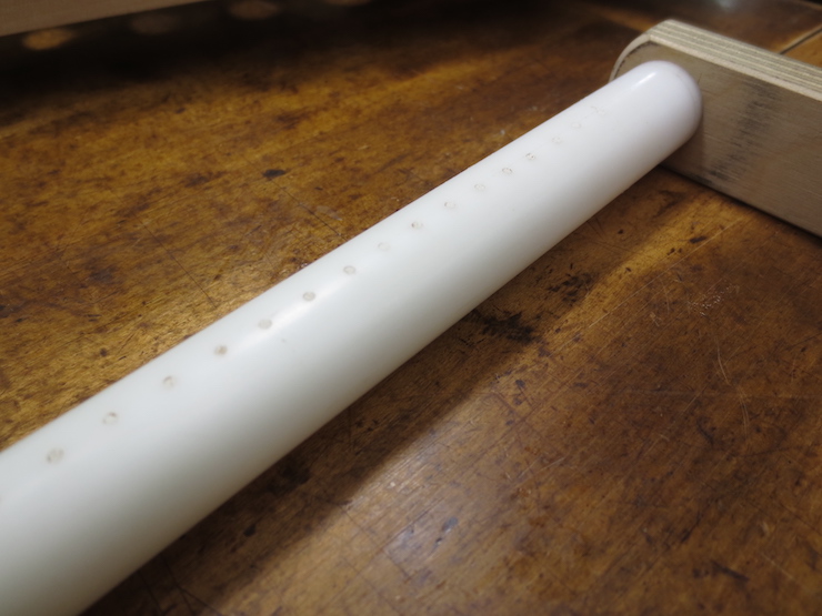
The cord reel is made of 3/4″ diameter acetal rod. A line of holes has been drilled into it for nearly its full length. The spacing of the holes isn’t too important. (about 1/4″ is good).
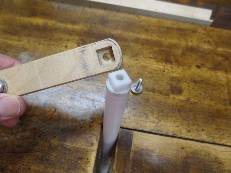
At one end a crank is attached by a machine screw in a threaded hole. The square shank and mortise allow the crank to be re-positioned. This makes it possible to correct the orientation of the reel after attaching the cords and drive weights.
Two pairs of metal posts (located at thirds) keep the reel from being pulled forward when drive weights are attached. The reel needs to be elevated above the top of the rack to provide room for the cords. Plastic shims placed over the posts elevate the reel in the middle. The ends of the reel are already held up by the holes through the end plates.
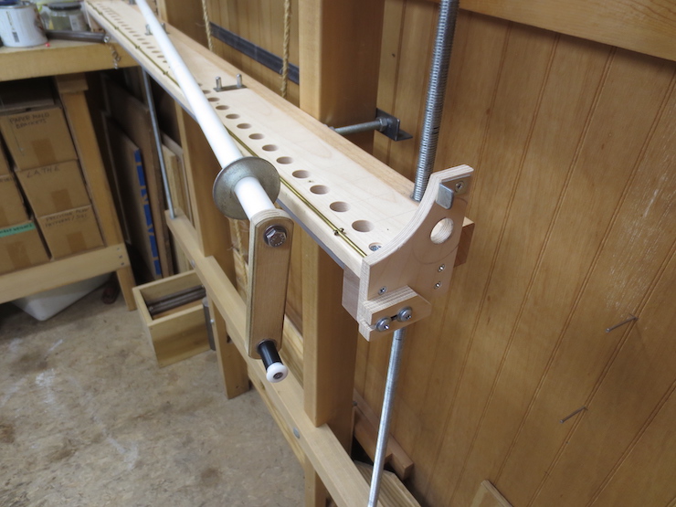
The cord reel is ready to insert through the big hole in the end plate. A large washer keeps the crank from rubbing against the end plate.
The reel passes through the left-hand end plate in the same way.
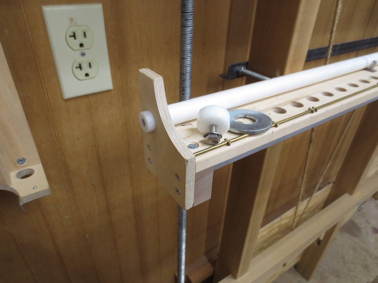
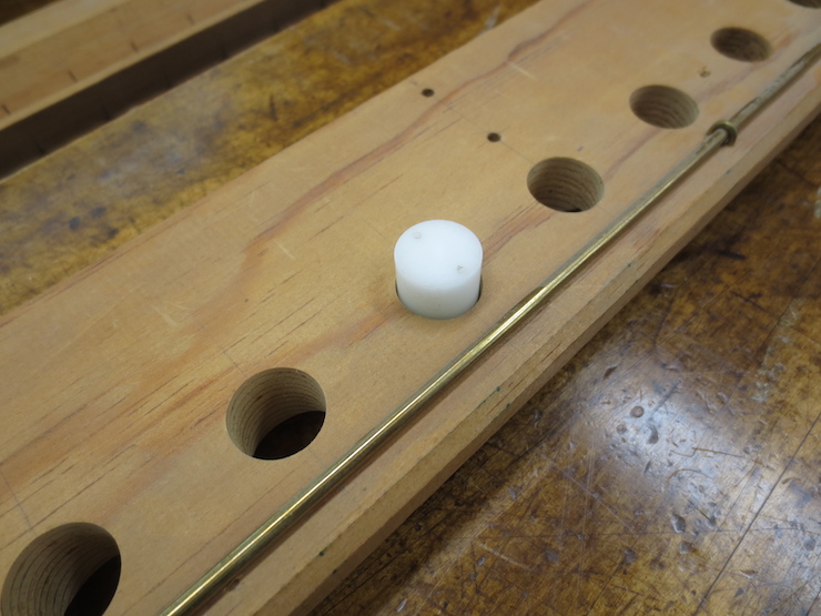
It is held loosely in place by another washer, a plastic cap and a small machine screw.
Wire Trough
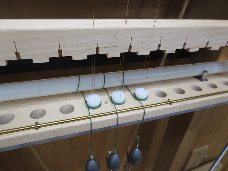
This is the wire trough which covers the row of spindles. The V shape makes it easy to slide laid wires in (one at a time). The cross-wise slots allow the pairs of chain wire to remain spread out (when lifted) so laid wires can pass between them. The slots also engage the lifted chain wires to prevent the spindles from turning backwards as the crank and reel are reversed.
This design is more complicated than it needs to be and I will show a simpler version at the end of the post. These were made this way to solve a problem; it was possible for the loops of cord that are wound around each spindle to slip up off the top. This happened when a drive weight was accidentally bumped from below. Two changes were made. First, the spindles were lengthened from 3/4″ to 7/8″ so they would stick up farther above the cord loops. Second, the wire trough was shaped to enclose the tops of the spindles and prevent the cord from slipping up that high. Both work very well to prevent these occasional accidents but simply lengthening the spindles may have been enough.
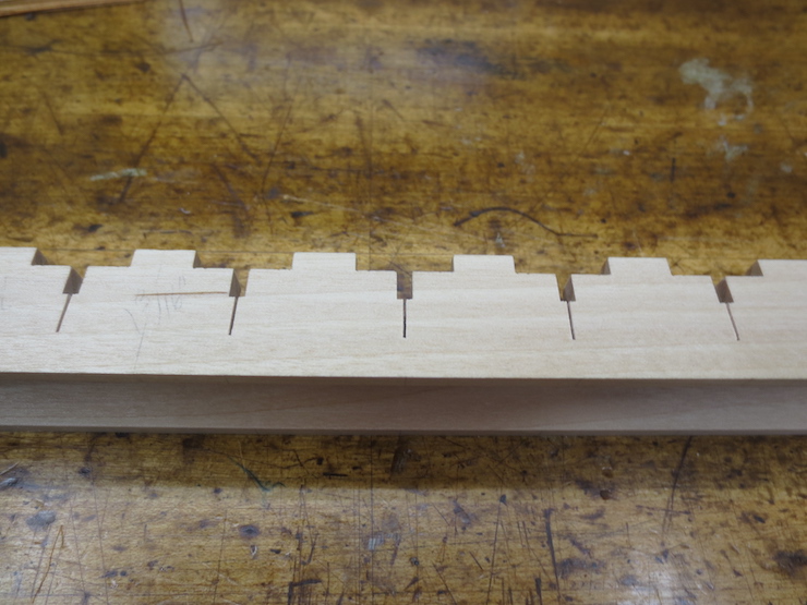
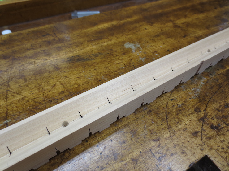
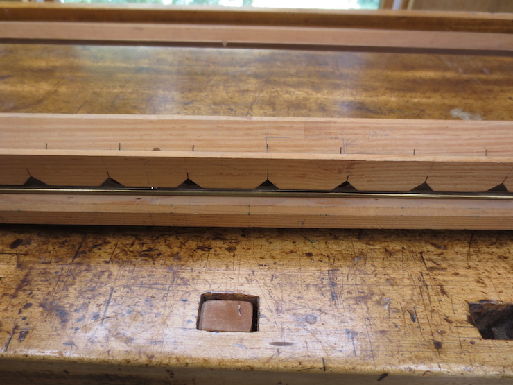
The trough lying on its side. The very narrow saw cuts were made with a Japanese style backsaw held in a cross-cut jig.
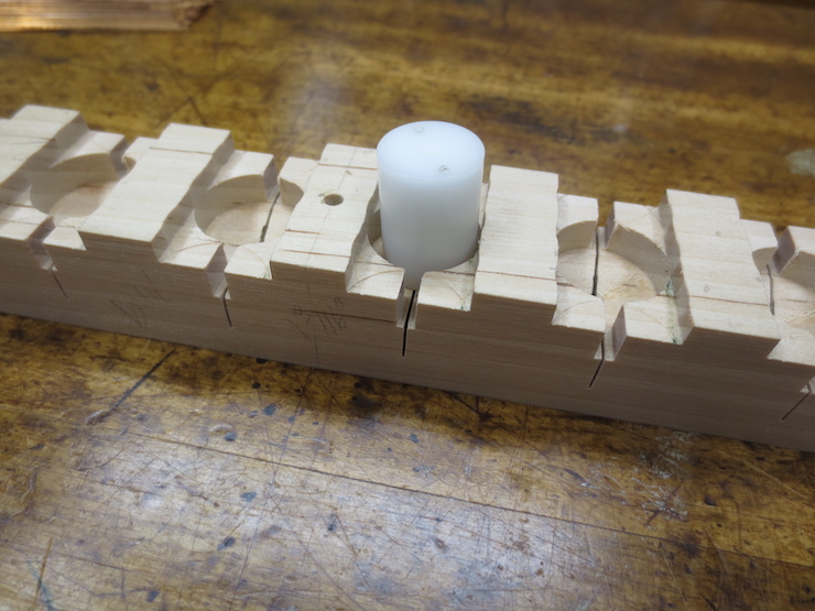
The wire trough is laid upside down to show how the top of the spindle is enclosed to prevent the cord from slipping off the top.
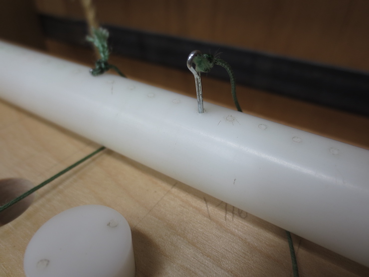
The holes in the cord reel receive these tiny cotter pins to connect the weighted cords to the reel. The cotter pins start out too long and have to be snipped off a bit. The knots at both ends of the cord are fixed with ‘Crazy Glue’. As mentioned the spacing of the holes is not critical, the location of each cord attachment just needs to be fairly close.
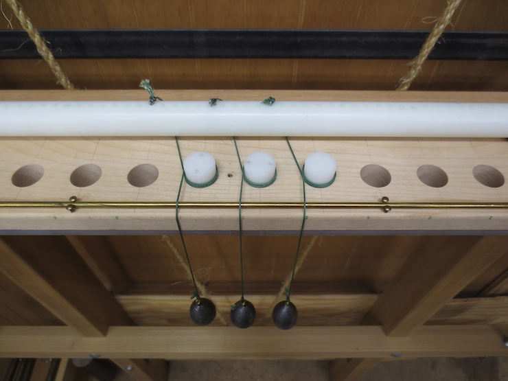
The cords are fitted with the holes in the reel pointing straight up. (Just to make it easy to put the cotter pins in). After all of the spindles are hooked up the crank can be loosened and slipped out of its square mortise so that the weights can be reeled in the right amount. (If they hang down too low they get in the way.) After the adjustment is made the socket of the crank is firmly tightened over the square shank of the reel.

The ends of the cotter pins should start at the back and end up in the front when the weights are cranked up fully. This way the pins and knots stay on top as the reel is turned back and forth. The purpose of the 1/8″ brass rod fastened along the front is to elevate the cords at the front of the spindles. This prevents the cord loops from lapping over each other.
This photo provides a good illustration of the problem mentioned a few photos back. If a weight is bumped from below the loops of cord might loosen and slip off the top of the spindle. This was even more likely with the original spindles which stuck up only 2/3 as far as these do. The more elaborate wire trough I now use prevents this from happening.
Chain wire is added with the wire trough elevated. This process is covered more fully in other posts.
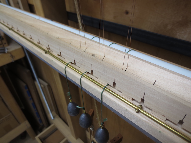
When the wire trough is lowered over the spindles and screwed down the assembly is complete. For this post only three chain wires have been used. Normally there would be many more chain wires, spindles and weights.
Older, Simpler Parts
When it came to time to make a second loom I tried to refine the design using everything I had learned over the years. But some of the original features were very functional and easier to make.
An example of the original wire trough made of pine from a lumberyard.
Pairs of screws work as little ‘jacks’ which are adjusted to hold the bottom of the trough just above the spindles. If longer spindles were used (7/8″ or even 1″) longer screws could easily be adjusted to fit. This might solve the ‘cord over the top’ problem mentioned earlier in this post.
The spindle racks were also a little crude but worked well for as long as this loom was in service.
These were also made of pine which has some advantages. The original spindles were cut from 5/8″ diameter acetal rod and filed smooth on the ends. (I didn’t have a lathe). This material is manufactured slightly oversize so the 5/8″ holes drilled in the wood fit too tight. The holes were easy to enlarge with a strip of coarse sandpaper and dowel chucked into an electric drill. As you can see above the spindles can be quite loose.
