This doesn’t include straightening laid wires or sewing with wire. Both have been covered in earlier posts. In some ways this is a continuation of the last post, #55: Configurations of Laid Wire.

The wire used here is phosphor bronze. It is corrosion and fatigue resistant, stronger and much better for mould making than copper or brass. The wire used for chain wire twists is soft (annealed) and the wire that is straightened for laid wires has some temper. For years I used only spring tempered for the laid wires but I have been told that 1/2 hard is what was used at Amies. I have since tried 1/2 hard and 3/4 hard to make laid wires. All worked well though, in general, harder tempers may be a little more difficult to straighten.
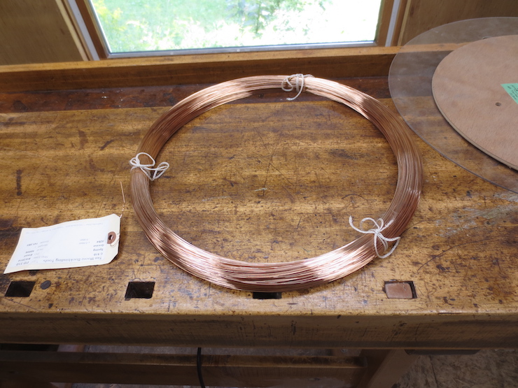
Wire is often supplied in coils. A coil alone is not convenient and needs to be supported on a reel to make it easier to use.
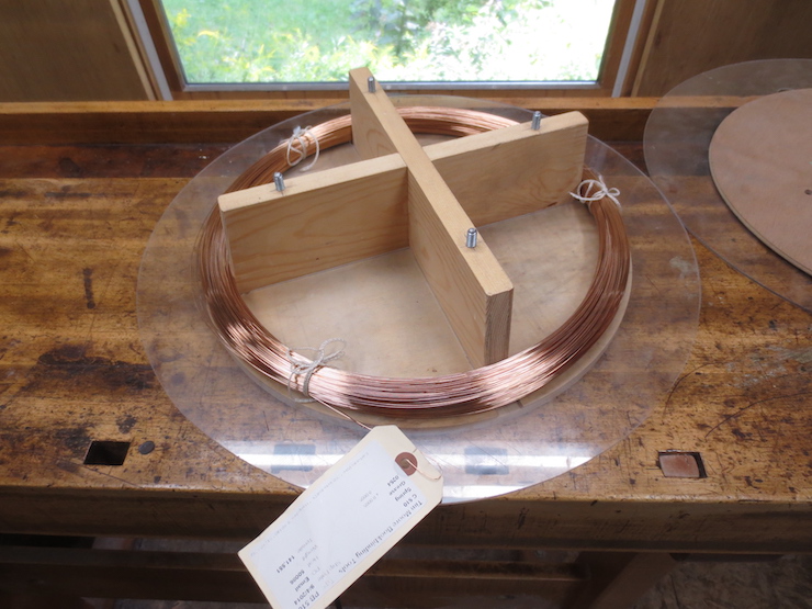
Here is a reel that I made. The base is a thick plywood disc. It has a hole in the center so it can turn on a steel rod mounted in a block of wood.
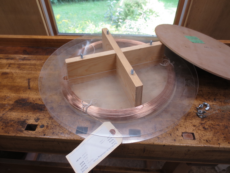
I made two identical plastic discs to fit the reel. The lower one extends the size of the reel to better support the wire. The upper one floats on top of the coil to keep loops of wire from flipping off the top. This is probably not needed, but I had a bad experience early on with a coil that turned into a rat’s nest. A thin plywood disc can be fastened to the top after the wire is in place..
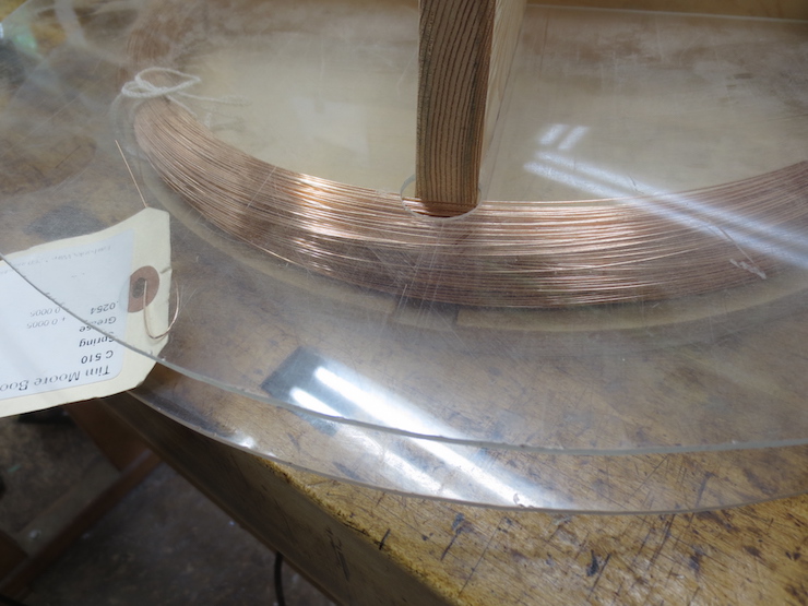
A closeup showing the coil sandwiched between the plastic discs. It’s important to keep track of the end of the wire so it doesn’t cross under some of the other loops. I always put the tag back on so the end doesn’t get lost.
Spools also need support to make it easy to take wire off for stringing up the loom or when sewing a mould.
This works well too. The end of a long bolt is clamped in the tail vise of the bench.
The vernier caliper makes it easy to identify sizes of laid wire. The micrometer is used to measure chain wire since differences in size can be less than a thousandth of an inch.
How Tightly can Chain Wires be Twisted?
A number of factors are in play here. How soft is the wire? How large is the wire? How heavy are the weights at the bottom of the wires? Another important consideration is the angle that the wires are splayed as they are twisted by the spindles.

This cross-section schematic is drawn to scale to compare the two angles of splay used in this loom. The red lines represent the chain wires. The black V-shapes show the inner surfaces of the wire trough that supports laid wires (one at a time) while the chains are twisted around them. The tightest twists can be made using flat-topped spindles, one of which is outlined on the left in light green. In the drawing you can see that these wires are splayed widely by the holes in the spindle. More relaxed twists are made using spindles with recessed tops, like the one on the right (outlined in turquoise). The recessed area effectively changes the height of the spindle so the wires are splayed less widely. Every spindle has both a flat end and a recessed end, either of which can be placed upright.

Here pink lines have been added to show what happens to the (previously red) wires when they are twisted around a laid wire. The flat topped spindles are used for laid facings; the recessed ones are better for making widely spaced backing wire.
When a laid wire is placed in the wire trough it rests a little less than 9/16″ above the top surface of the spindle rack.

The spindles stick up above the spindle rack exactly 3/8″. After the wire trough is screwed down, covering the spindles, the distance between the top of the spindle and the laid wire ends up a little less than 3/16″. If the spindles are inverted the distance from the top of the recessed area (1/8″ lower) to the laid wire ends up at about 5/16″. The 1/16″ diameter holes are drilled 7/16″ apart. The two angles of wire splay created by these dimensions work well, each for a specific purpose.
Testing Wire on the Loom
Determining how tightly two specific diameters of wire can be combined.
It is helpful to know the tightest spacing possible for different combinations of wire. This lets you choose among spacings that are sure to work and to more accurately predict the results when testing a different combination for the first time.
A Wire Test with Notes
You only have to do this once for each wire combination.
A relatively loose spacing is chosen for the first section of the test. After an inch or so has been made the counting wheel is changed and a slightly tighter spacing is created for the next section. Counting wheels are changed and increasingly tighter test sections made until the wire starts to bulge when it is lowered. When this happens it means that the limit of this combination of laid and chain wire has been reached.
Test for the wire shown above:
Wire Combination: .0254″ laid wire / .0118″ chain wire / tight twist spindles (flat on top)
20 wires were added in each section.
Spacing is in wires per inch.
| spacing | pins x clicks | percentage space/wire | notes |
| 18.20 | 7 x 5 | 54%/46% | worked well |
| 18.35 | 24 x 17 | 53.4%/46.6% | worked well |
| 18.42 | 17 x 12 | 53.3%/46.7% | worked well |
| 18.47 | 27 x 19 | 53.1%/46.9% | worked well |
| 18.57 | 10 x 7 | 52.8%/47.2% | started sagging but tightened up with twist |
| 18.69 | 23 x 16 | 52.6%/47.4% | same as above |
| 18.78 | 13 x 9 | 52.3%/47.7% | this one sagged noticeably after twist |
Conclusions from the test: It is safe to use this combination of wires with the first four spacings (and any of the looser ones before them if you wish). The next two intervals are iffy and the last one won’t work. If you want to use .0254″ laid wires for any of the last three intervals try the next smaller chain wire, (.0113″ in my case). This should do the trick and isn’t much of a change; the wire is only five ten-thousandths of an inch smaller in diameter.

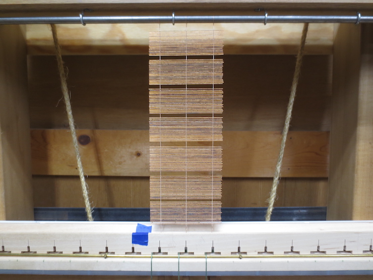
When the spacing is too tight the web of wire will increase faster than the space in the loom does. That’s why the wire begins to bulge. In this photo the splayed chain wires are sitting down hard on the newest laid wire (lying at the bottom of the trough), forcing it to support the wire and all of the 1 lb. weights below. If the loom is working properly the wire and weights should be supported by the steel lift rod alone. The loom can only regulate the spacing if there’s a little bit of slack between the chain wires and each new laid wire. Some slack is needed to allow the wires to conform to the spacing being set by the loom. The section below may explain this a little better.
Start the Wires a Little Loose
The first laid wire of a facing is left loose on purpose This works just fine and is better than starting too tight. The chain and laid wires will even out within a wire or two and the spacing will be regular from then on.
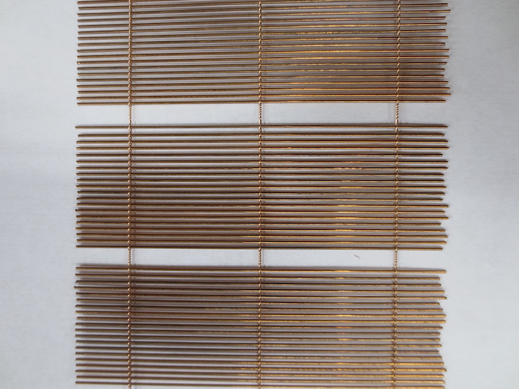
You can see this clearly at the top of the middle section. It’s not as obvious in the bottom section.
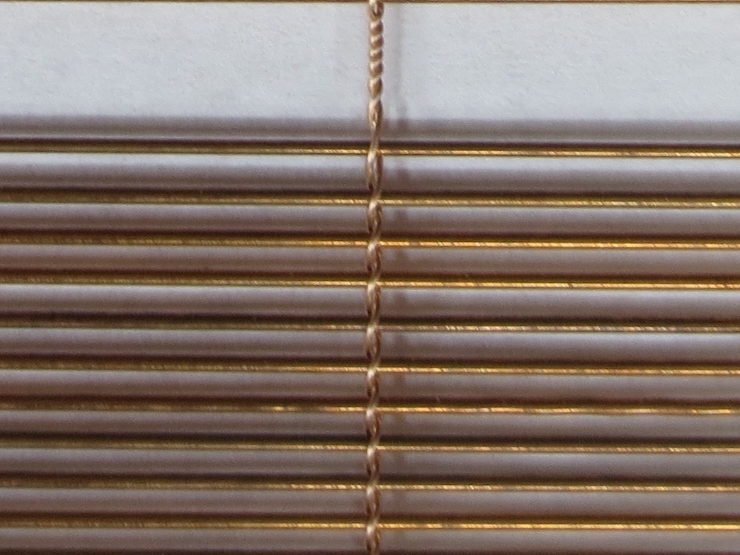
It doesn’t matter exactly how loose the wire starts, it just needs to be a little loose. Notice that the chain and laid wires immediately settle into the spacing dictated by the indexing mechanism of the loom. One or two loose wires don’t matter anyway because a few extra wires are pulled out while fitting the facing to the mould.
Wire Weights
The weights should hold the wires taut without being so heavy that they stretch the wire. They should all weigh the same amount. And theoretically they should be just heavy enough to work well with the heaviest chain wire that will be used. I have used 1 lb. weights for many years but can no longer remember what happened when other sizes were used. It is possible that these weights could be a little lighter since now they are only used with annealed chain wire. I was working with 1/4 hard chain wire and this may have influenced the decision to use 1 lb. as a suitable weight.
