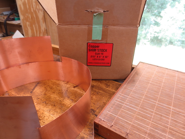
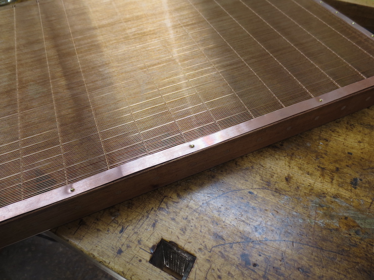
Copper shim stock .015″ thick makes good edge strips. These are needed to protect the edges of the laid and chain wires. But before the strips can be fastened in place there are a few more steps to be done.
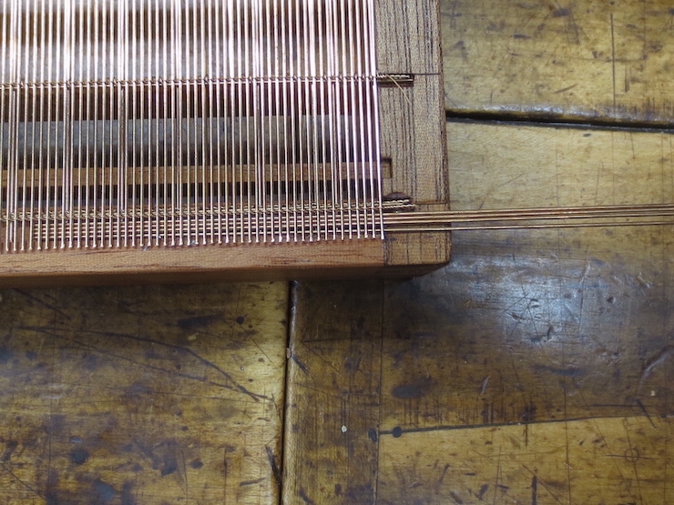
Bridge wires are inserted between the laid facing and the laid backing at both ends. These add support to the top wire layer so it won’t be distorted as badly when the strips are nailed down.

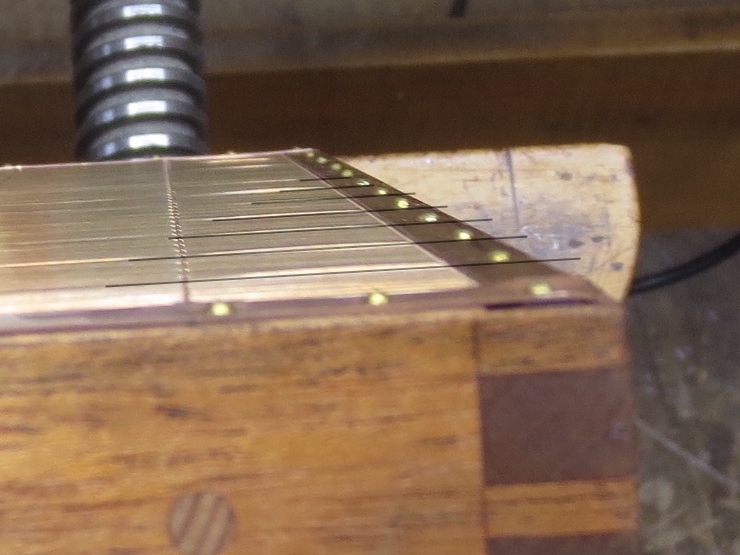
Here you can see one bridge wire trapped between the upper and lower chain wires. It extends into the notch at each end along with the chain wire twists. The other bridge wires are shorter, just long enough to fill the space between the layers above the lower ledge. Cross section drawings in a previous post show this more clearly. (Finishing The Mould Frame)
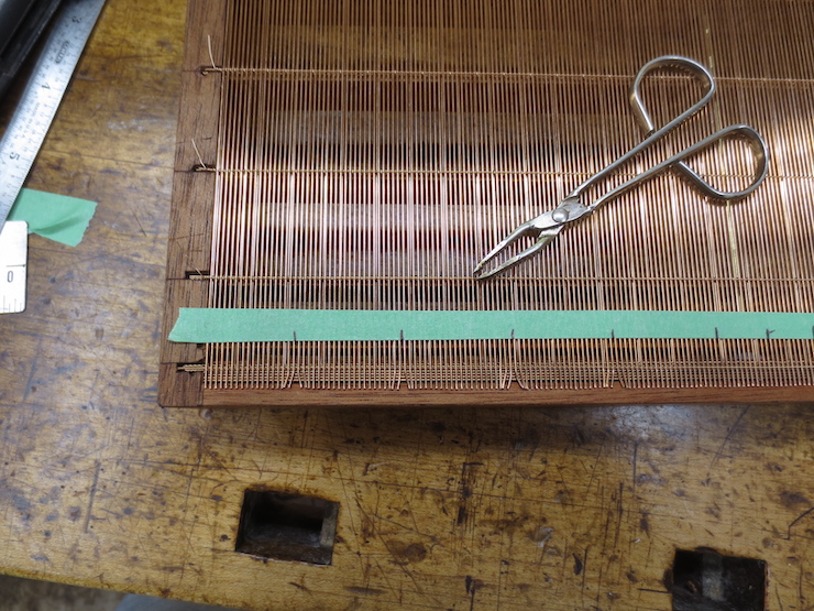
The locations of nails are marked and laid wires are bent sideways to make room for the brass escutcheon pins that will be hammered in about every inch.
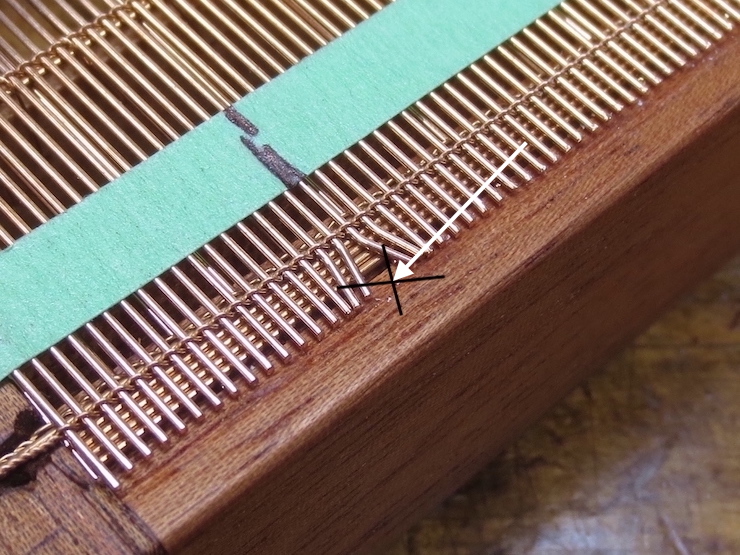
“X” marks the spot where a brass nail will enter the wood.
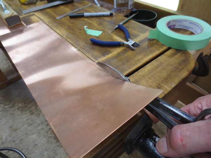
Strips are cut from the shim stock. Running them over a sanding sponge rounds off the sharp edges that are left.

The ends of laid wires are now hidden but marks on the tape indicate where spaces have been created for the nails.
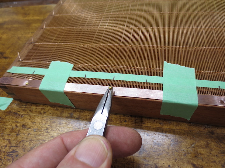
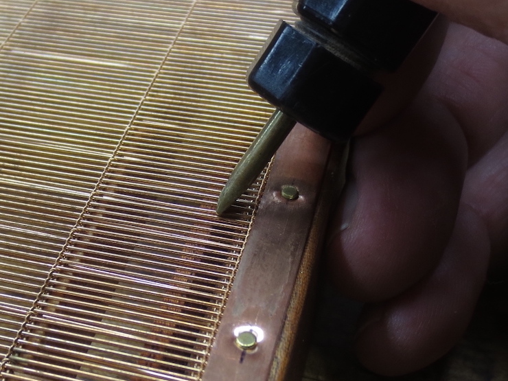
A sharpened nail set (below) is used with a small hammer to pierce the copper and start holes into the wood. These cross-grooved needle nose pliers are used to hold the nails while they are started with a hammer. On the ends of moulds every third nail is 3/8″ long. The rest are 1/4″. The corner nails are 1/2″ long. The nails are #18 brass escutcheon pins. They are .050″ diameter with small domed heads. British moulds typically use copper wire nails with flat heads. The ones I have measured are made of 1mm (.040″) wire. I have not been able to find a source for these.

This is the altered carpenter’s nail set that is used to pierce the copper strip.
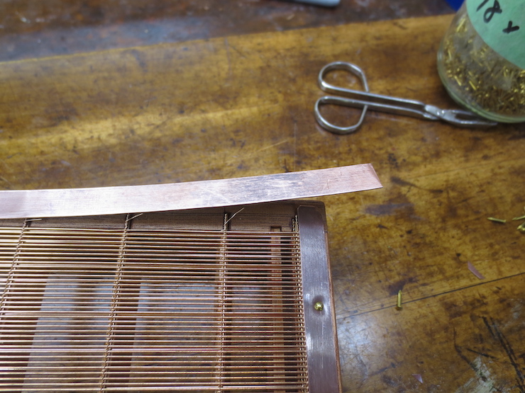
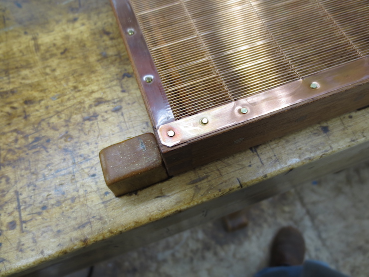
The end strips have been attached, protecting the ends of the laid wires along both ends of the mould. Two more strips are applied parallel to the laid wires to protect the fragile extensions of the chain wires.
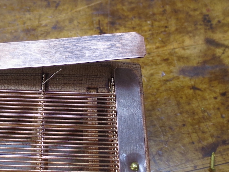
The bottom strip has had its outside corner snipped off a bit farther in than the upper strip. After both strips are nailed in place the corner of the upper strip can be burnished down over the lower one.
Along the sides a nail is placed just to one side of every twist. These nails are 1/4″ long.
Nails sometimes loosen with use. They can be tapped back down or if necessary replaced with the next longer size. On occasion I have screwed the edge strips in place with tiny #2 flat head brass screws. (Slightly larger #3 screws were used on the four corners.) This works very well but adds considerable time and expense.

After all the nails are hammered in the soft copper is burnished to lie tightly against the wood.
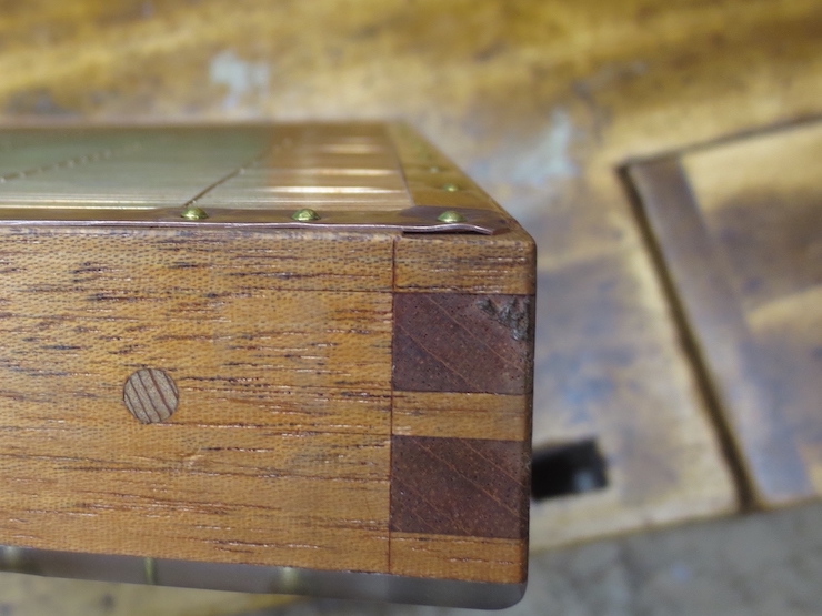
As mentioned the upper strips are burnished down at at the corners
Even with the support of the ledges and bridge wires the force of the nails causes laid wires to distort.
This tool is just a piece of brass rod clamped into a file handle. The end is blunt and the sides tapered like a screwdriver. It is used to poke and prod the laid wires, bending them a little to make them lie fairly straight again.
The tops of the escutcheon pins are carefully filed off to leave clearance under the deckle rim. A misdirected stroke with a file could easily destroy a chain wire!

The mould is finished (but needs a deckle)!
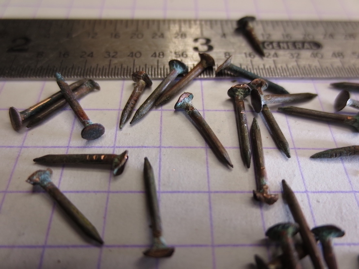
Some of the tiny copper nails extracted from British moulds during repairs.
