(And a few other things).
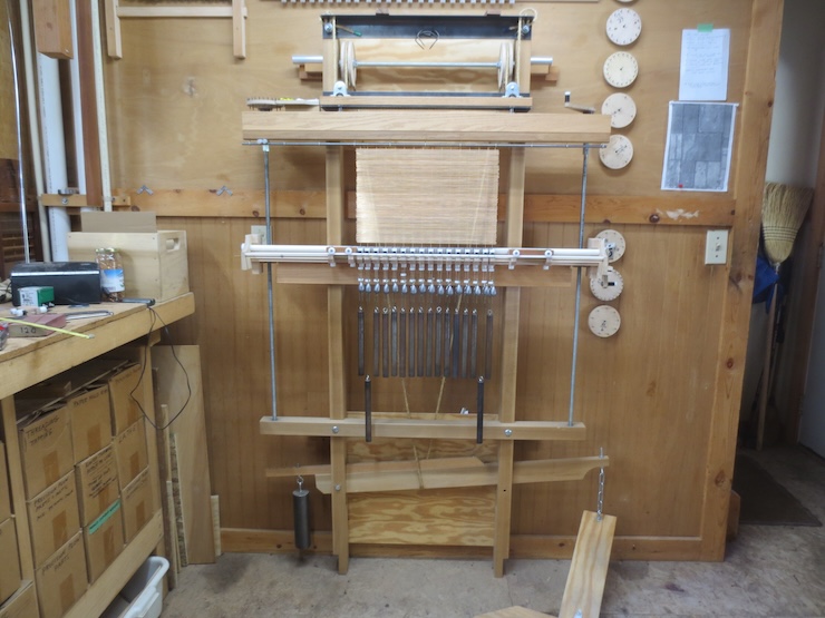
Lots of loom developments this year! Soon after the first set of adjustable spindle units was finished I became aware that an unusually narrow chain wire spacing is being used by at least one paper maker. The chain wires that I saw were only 15-16 mm or 5/8″ apart. This was something my loom couldn’t do! This got me wondering if it would be possible to make these using smaller spindles. While making a new set of parts I discovered a few new things. Updates here.

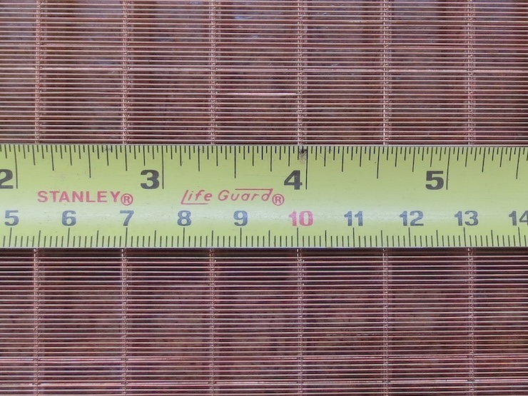
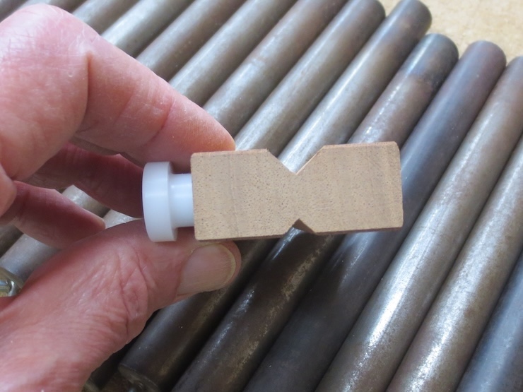
The smaller spindles worked fine using the same drive weights and the same three wraps of the drive weight cords. The small ones are 1/2″ diameter, the larger, original ones 5/8″.

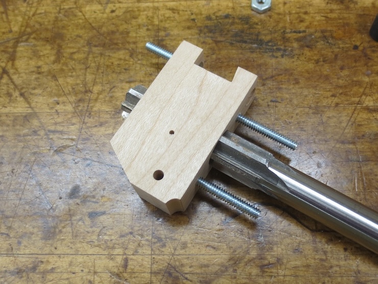
Here is a new spindle unit, one of almost four dozen made to complete a set. It is very similar to the ones described in post #63 but 1/8″ narrower. Using a metal dowel pin to hold the spindle up makes it easy to ream the spindle hole. Leaving the little curved notch at the front edge empty turns out to be a good idea.
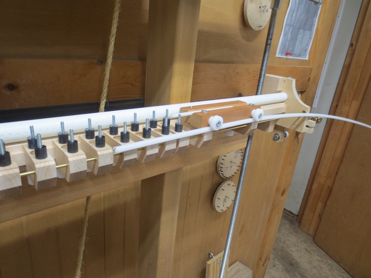
This is shown here. Instead of tacking short segments of rod to the individual units a length of 1/4″ diameter acetal rod is put in after the spindle units are fastened on. This is easier and adds one more bit of bracing to keep the spindle units lined up.
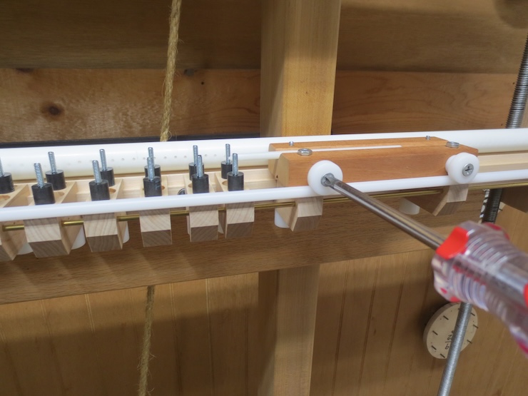
The rod extends the full width of the loom and sits neatly in the notches. It is clamped in place by tightening these screws.
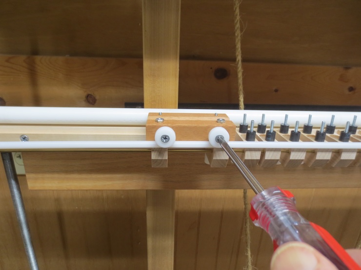
The other end is clamped to the block that catches the shuttle after the laid wire has been run through.

This is the older, thicker ‘prototype’ spindle unit showing how a short segment of the rod was tacked to the front.
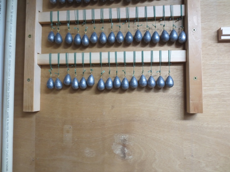
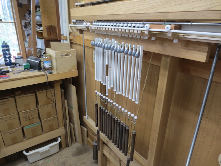
The weights that drive the spindles are now stored like this with their cords wound onto rectangular sticks. The sticks slide into notched bars fastened to the wall. Storing the weights and cords had always been a problem and this works really well.

The stick is unwound…

…and clamped to the bench where weights can be easily be removed one at a time.
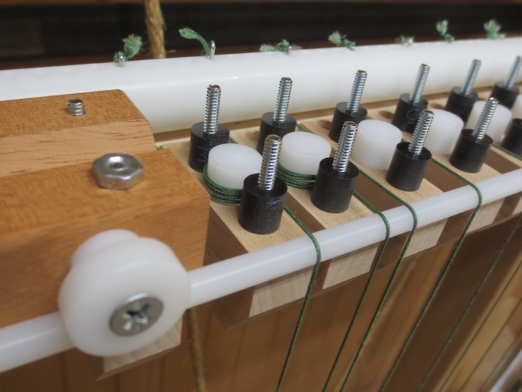
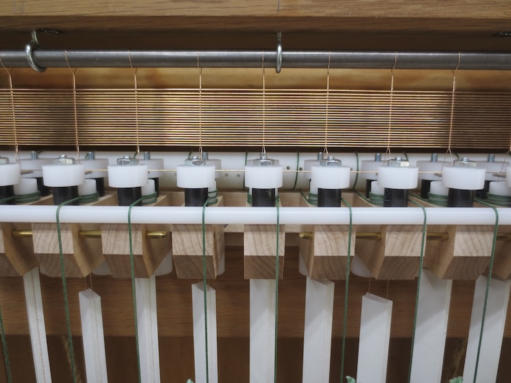
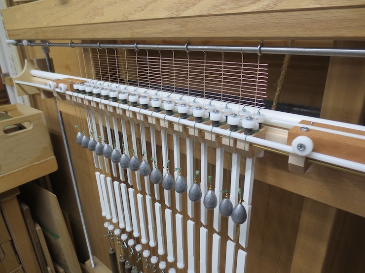
Now that the drive weights are added you can see another advantage of the continuous rod. The cords have no chance of slipping off into the gaps between the spindle units. The rod has two purposes. It provides a slippery surface for the cords to slide across and it elevates the cords in front so the cords stay separated as they wrap around the spindles and don’t overlap.
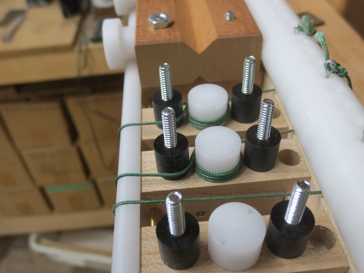
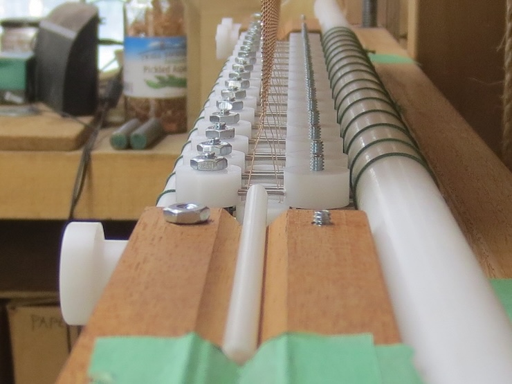
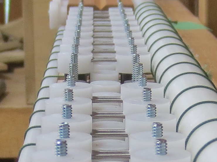
The metal rods in the new wire supports are stainless steel dowel pins, 1/16″ diameter by 7/8″ long.
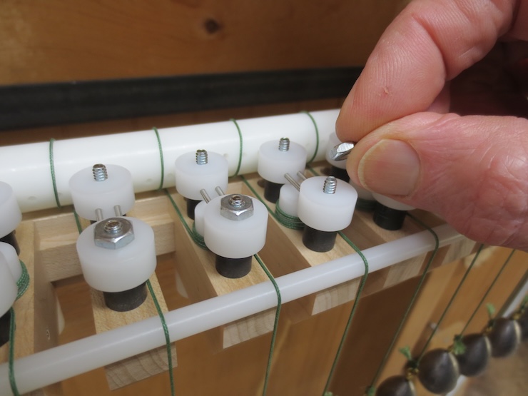
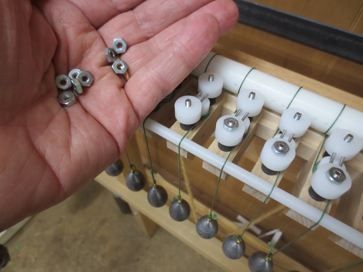
Nuts are needed only on the front studs. Finger tight is good.
These smaller wire slides are just under 5/8″ diameter to allow the narrower wire spacing to be made.
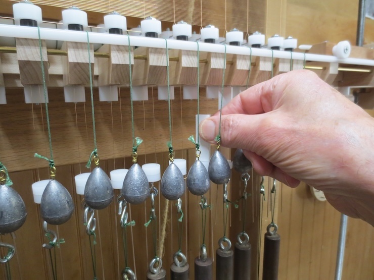
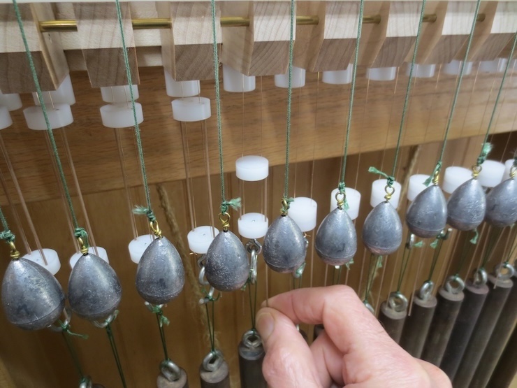
It turns out that 3/4″ diameter wire weights can be used to make 5/8″ chain spacing. All you have to do is hang half of the weights lower than the other half by using longer loops of cord. (Every other weight).
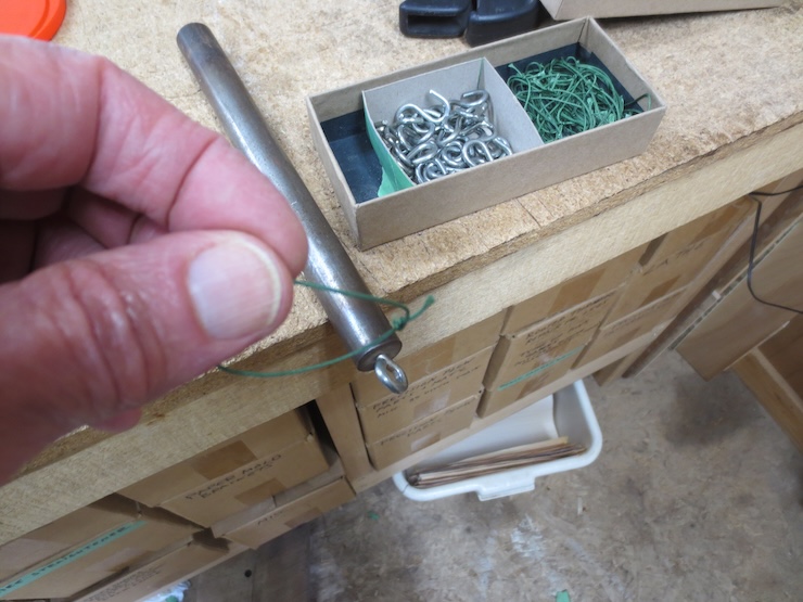
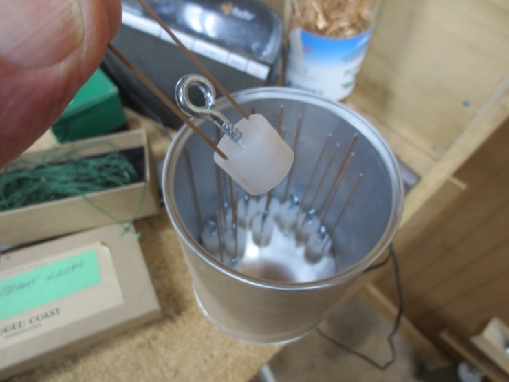
Needing two sizes of loops led to a more convenient way to store the wire weights; disassembled. To use, a weight is taken from its storage box, laid flat…

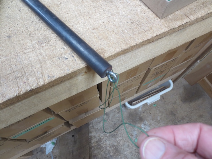
…and a prepared loop is cinched through the eye bolt.

Then an ‘S’ hook is added to connect the weight to the wire slide. No more tangled hooks and loops.
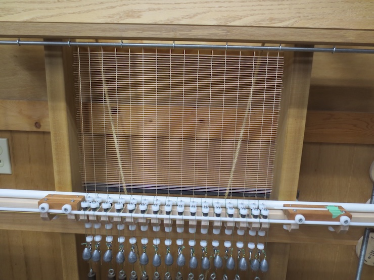
Only two of these longer loops are seen here because all of the middle spaces are wide; only the two end spaces are narrow.
A laid wire will be inserted into the shallow tapered hole seen at the near (blurry) end of the shuttle. The shuttle guides the wire as it is pushed through (by that same laid wire).

After the wire is deposited onto the support rods the shuttle ends up resting in the groove. It is picked up and moved back to its starting place prior to inserting the next laid wire.

A single row of shorter foam board spacers at the bottom makes the last adjustments easier.
When removed, the shorter spacers leave a smaller space for the movable parts of the wire slides to fill. These can be pushed up to take up all the remaining space so the wires don’t twist up on themselves.
This is the first laid facing made with this new system of smaller parts that enable the loom to make the very narrow configuration (if needed). The next step is to test the newly outfitted loom by making a variety of sizes and types of mould.
Backing
The wire supports are flipped over to make a laid backing.
The ones in the back have been turned over to the higher position to give the wire twists a more relaxed angle for making widely spaced backing wires.
In post #63 I shimmed the shuttle rests up for backing wire. Now there are grooves of two different depths and the rests can simply be flipped over when changing from facing to backing.
This backing used the heaviest chain wire in my stock. It is .015″ in diameter annealed phosphor bronze. The heavier wires have a stronger tendency to twist around each other so it was a little trickier to keep the wire spacers in place. It’s delicate work to avoid bumping and dislodging the spacers while adjusting them. This is one place where the smaller parts seemed to have a (slight) negative effect. I more often use .013″ wire for this purpose which should work more easily.
Now I’ll try making all of my facings and backings using the smaller parts of this new system. If it proves to work well it could replace the older one.
A little more about the Spindle Units
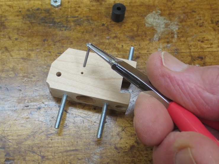
The bottom of each spindle is supported by a 1/16″ diameter stainless steel dowel pin.
These are easy to remove which makes it a cinch to ream the spindle holes. It is usually necessary to re-true the holes so the spindles don’t bind. This is because wood changes seasonally. After a year or two this won’t be needed.
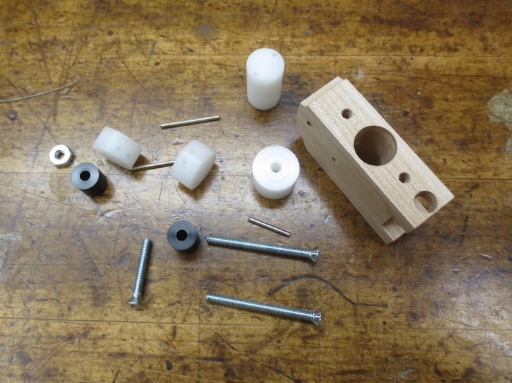
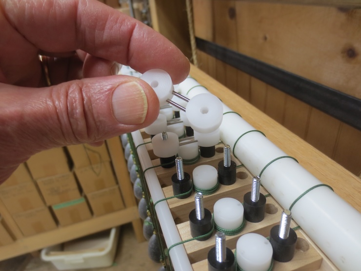
A disassembled spindle unit. Like the older spindle racks these are a challenge to make. But now only one set of these is needed to make any chain/rib spacing. And the minimum chain wire spacing has been reduced to 5/8″.
One more thing.

I’m not sure that this topic has been covered before. After the weighted cords are added the reel needs to be wound in a bit. To do this the reel crank is re-set. The crank is disengaged from the square shank formed on the end. After the reel and weights are re-positioned the crank is bolted back on to hold it there.
