I’ve been working with and gradually improving my mould maker’s looms for about forty years. I have tried a few times to figure out how to do this but didn’t get very far until now.
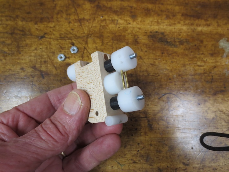
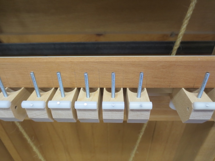
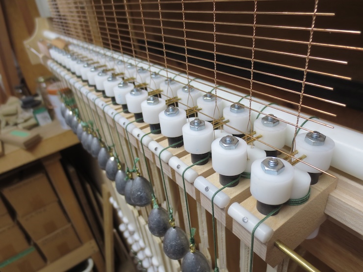
This is one of a number of spindle units that make it possible to create any spacing between chain wires. One of these is required for each pair of chain wires. The minimum (3/4″) is limited by the width of these wooden parts. But this doesn’t matter because it’s still a little closer than is possible with the weights and wire slides that this loom uses.
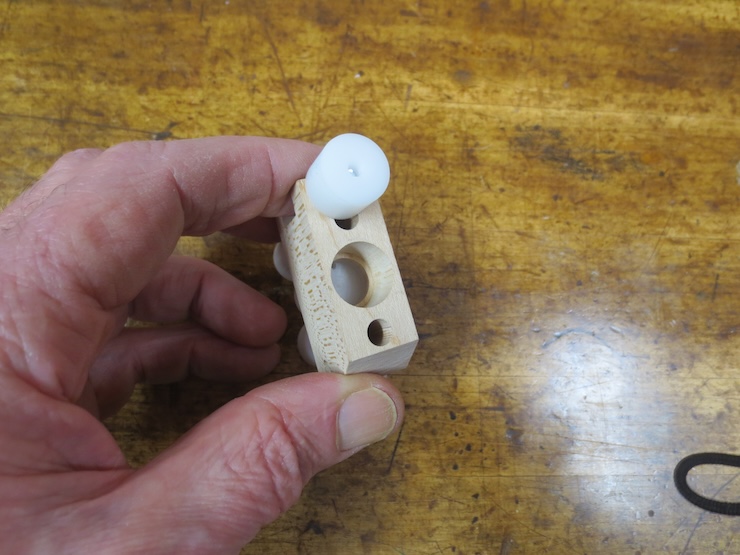
A view from the bottom. The white cylinder is screwed tight to lock the spindle unit in place.
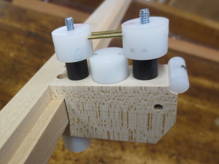
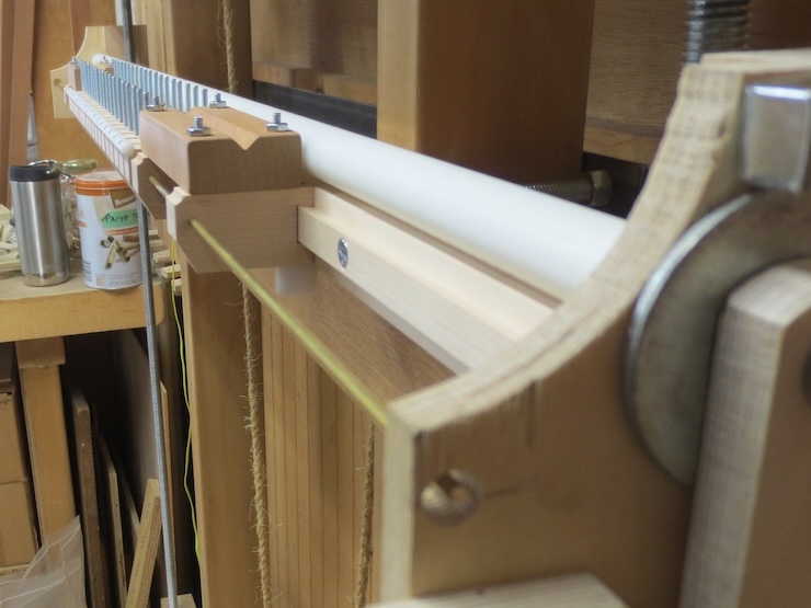
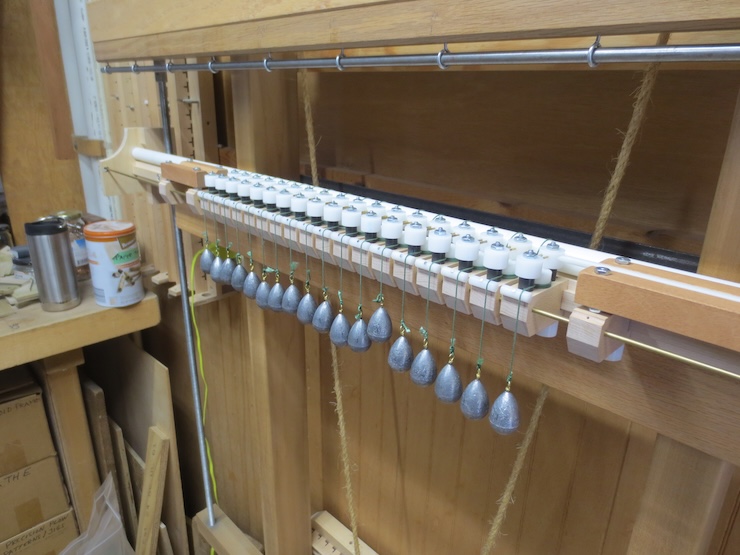
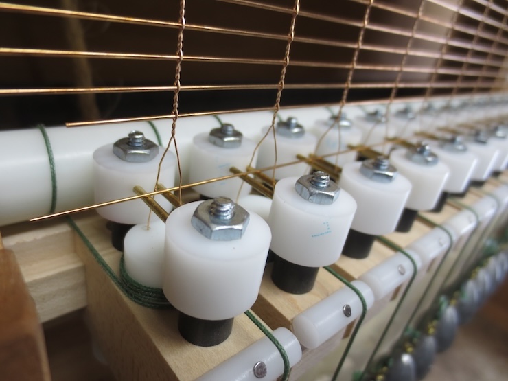
The units clamp to a wooden rail which is screwed to the traveling beam of the loom. A wooden wire trough (as with the previous spindle racks) is no longer needed. Instead a pair of 1/16″ brass rods held in place by plastic cylinders bridge the gap over each spindle to support laid wires as they are added. The wire supports can be placed in two positions, high or low. Here the pair of brass rods are high above the spindle to shape the more gradual twists of the widely spaced backing wires.
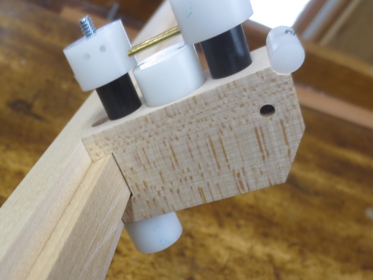
When making laid facings the support can be flipped over to put the rods in the lower position as shown here. This widens the wire angle to make tighter twists. The extra holes seen in both of these photos are the result of the experiments done to get the spacing right between the rods.

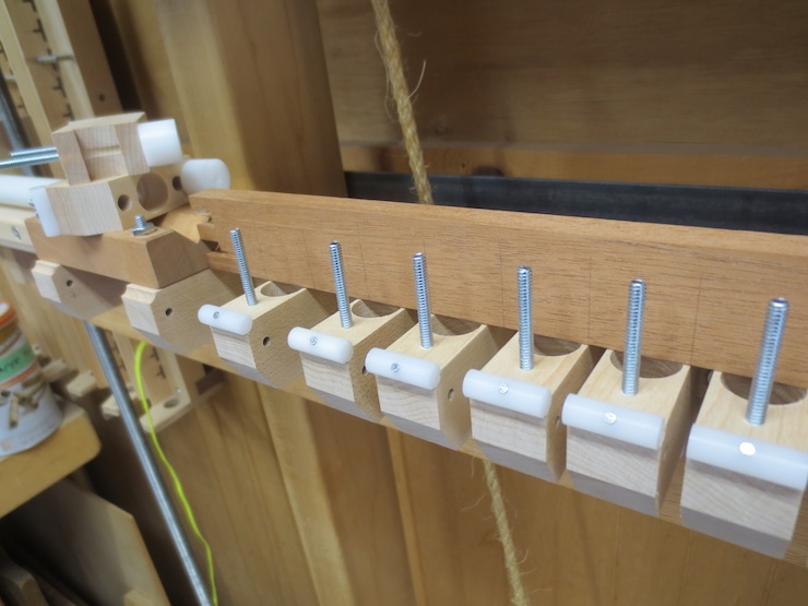
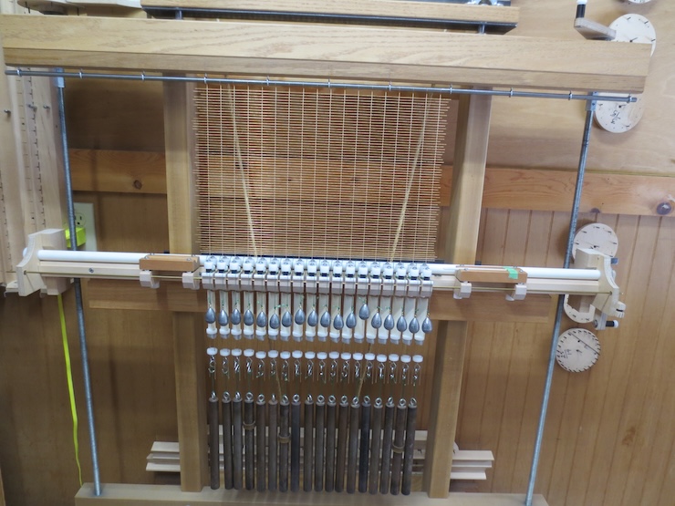
Eighteen identical spindle units are being installed to make a backing and facing for a 10″ x 15″ mould. One side of the unassembled mould frame has been marked with the preferred rib spacing and is being held in place while the spacing is transferred to the spindles. It’s being held between two other parts of the new system. That they can do double duty as clamps was a happy accident. The one on the right is designed to hold the shuttle in position just before it’s pushed (by a laid wire) through the openings in the wire above the spindles. The similar part on the left ‘catches’ the shuttle after it has finished guiding the wire through. There it can easily be picked up and moved back to its starting place.
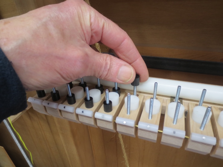
To transfer the spacing from the mould to the loom one edge of each unit is lined up with a mark then clamped in place.
The three on the right have been positioned. Additional ones can be tipped into place prior to clamping.
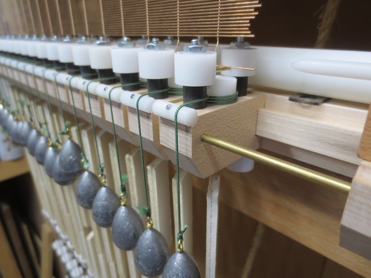
After all the spindles are in place the mould frame part is removed. A brass rod is passed through all of the spindle units to add an extra bit of security. If one unit should work loose it will still be held in place by its neighbors (though I haven’t found this to be a problem yet). These holes are drilled .003″ larger than the 1/8″ brass rod so it can easily be fed through by hand. It was more convenient to use two segments of rod. One was inserted from each end, placing the joint within one of the spindle units.
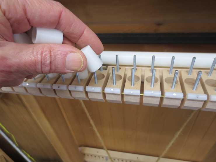
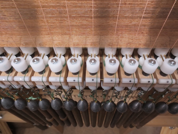
Now the spindles are dropped into place. This photo makes it look like the spindle goes over the threaded stud but it really goes into the hole.
The (white) spindles stick up exactly 3/8″ (.375″). The (black) spacers are longer (.385″) to hold the wire support parts a little above the spindle tops. When the parts are tightened down the gap will be small enough to prevent the drive cords from slipping up over the spindle top by accident. This is a problem to be avoided and this seems to be a good solution.

This new system makes many things easier but wrapping the spindles is a little more difficult with the studs and spacers in the way. On the other hand, the spindles won’t need to be flipped when changing over from making a backing to making a facing. Only the wire supports will be flipped so the spindles won’t need to be wrapped a second time.
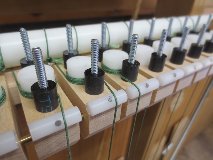
Another happy accident was realizing that the cord can wrap around the front spacer. This puts it closer to the center of the spindle unit so it won’t fall off the edge.
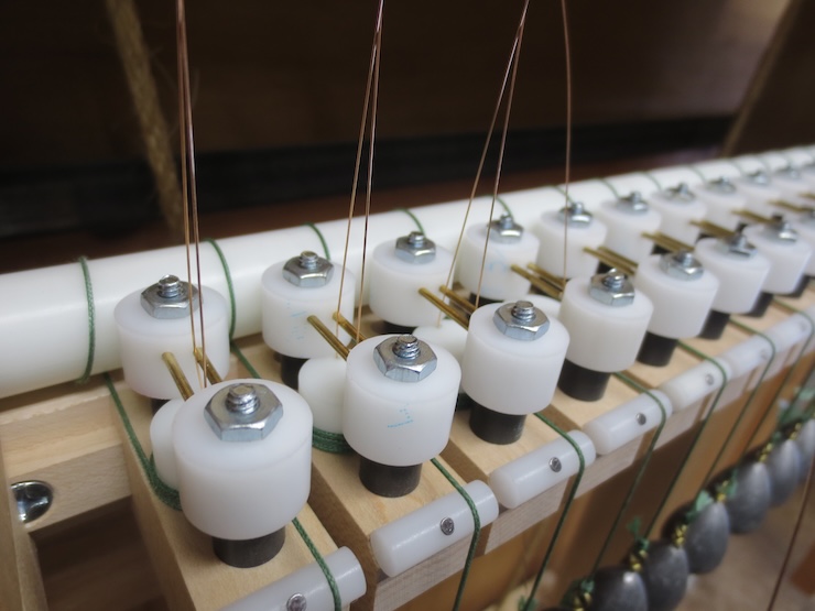
The wire support assemblies have all been placed over the spindles and are fastened down with hex nuts. These only need to be finger tight. The wire support rods have been placed in the higher position to make a laid backing.
With the new system it’s easy to stick the wires down through the holes in the spindles.

When making backing the shuttle rest needs to be elevated to match the higher support rods so the shuttle can slide evenly onto them. Here four 1/8″ thick nuts have been placed (not threaded) over the steel studs to lift the shuttle rest. I’ll make fitted shims in the future to make this easier.
The shuttle has guided a laid wire between all of the chain wire pairs. This works very well; there’s no room for the shuttle to stray off to either side. When the foot treadle is released the twists will settle down over the new laid wire. Then the twisting action will center the laid wire perfectly.
The backing worked well on the first try.
The first laid facing didn’t work out. The gap between the wire support rods was too small. I learned that if the gap is too narrow the soft, as yet untwisted chain wire gets distorted as it passes under the rods and can’t wrap tightly enough around the laid wires. After a number of tries a space of just under 1/8″ between the rods seemed to be best. The first two facings ended up being useless, but valuable as research. But all the laid wires were pulled out and used over again.
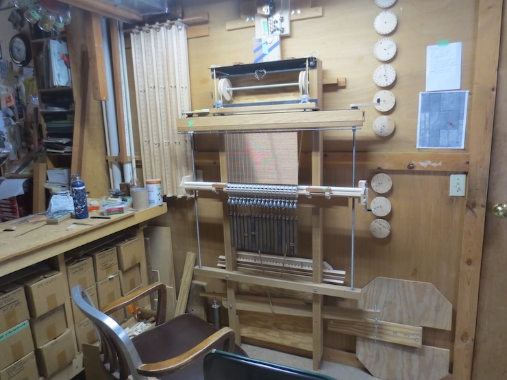
The final facing in progress.
Below the finished facing you can see the wide gaps between the wire support rods. I had previously assumed that it was necessary to make the gap narrow to keep the twists from slipping backwards.
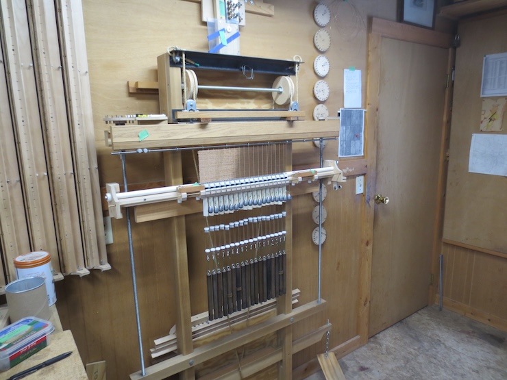
The seven wooden spindle racks visible in the photo now seem to be obsolete.

When using standard fixed spacings (7/8″, 15/16″, 1″ 1-1/16″ etc.) there is often a problem in adapting the spacing to the size of the mould. Spaces at the ends of the mould may be too big or too small. Now it is possible to simply divide the mould frame into whatever spacing is best without relying on any standard system of measurement.
