Assembly of the Mould Maker’s Loom
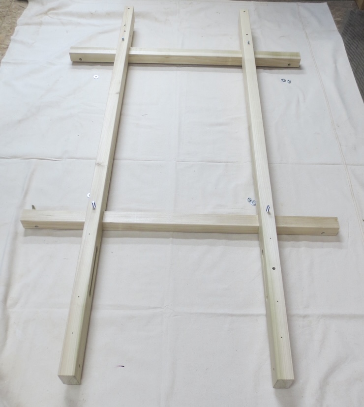
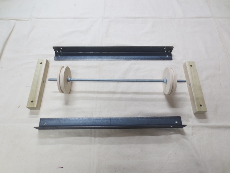
The loom frame lying face down showing the four carriage bolts that connect the parts.
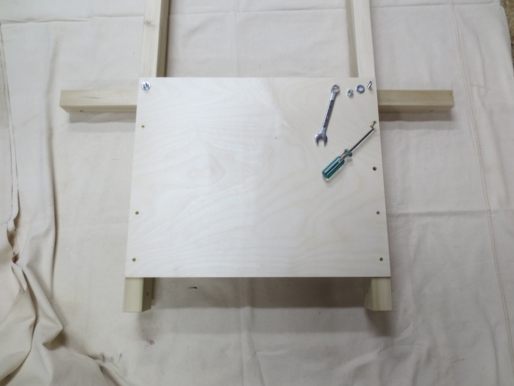
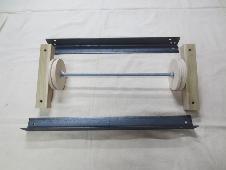
Fasten the lower brace panel to the back of the loom with six screws and two bolts.
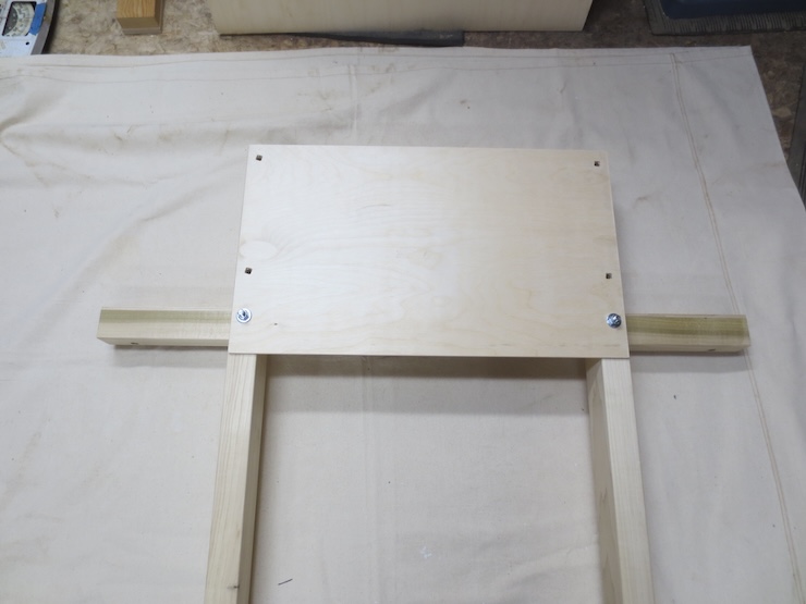
The top panel for now is secured only by two bolts.
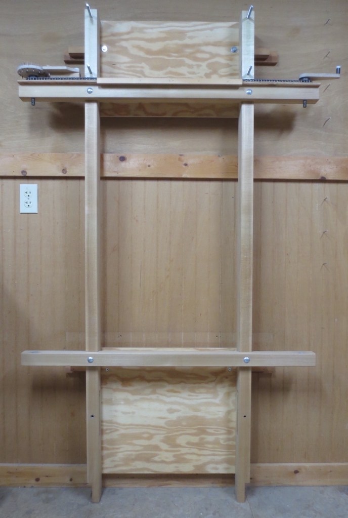
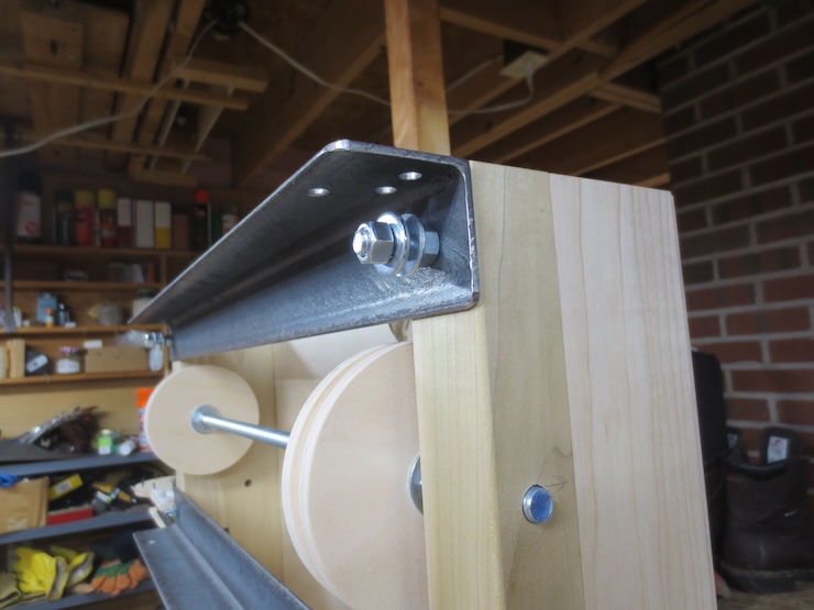
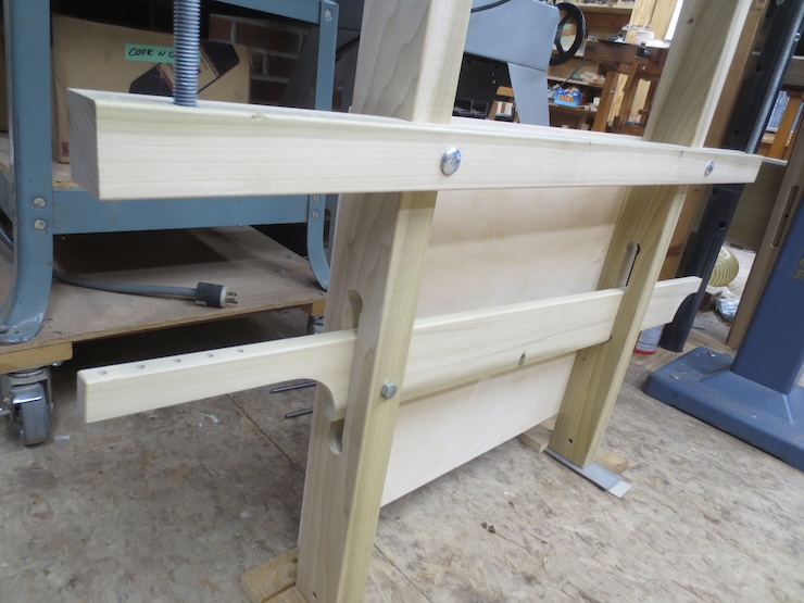
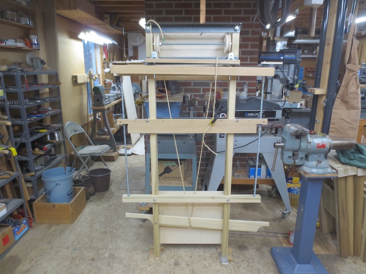
Now the loom should be attached to a wall structure in four places like this loom is. Two bolt heads can be seen just inside the uprights near the top and two screws heads can be seen in the bottom panel just below the lower cross piece. To level the loom one of the legs may need to be shimmed up. Then to make the uprights plumb shims are added behind the bolts or screws where needed. In this photo two wooden cross pieces were first screwed to the wall. The loom was then attached to these. The cross pieces also hold the loom away from the wall to allow room for the moving parts.
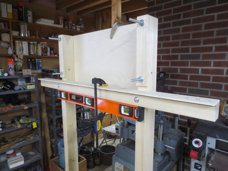
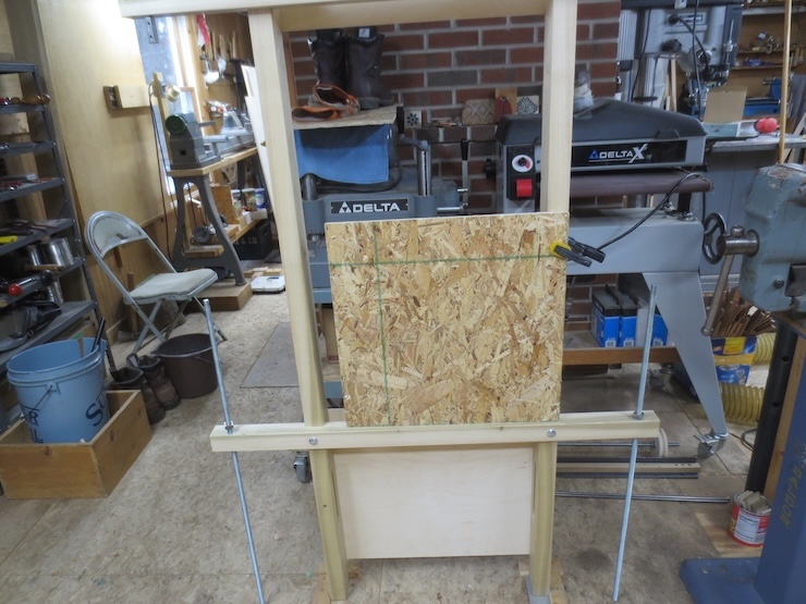
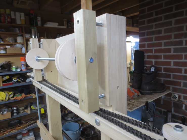
The loom has been stood up and braced in place temporarily. I don’t have any available wall space in the shop where I am building this loom. Four more bolts have been added through the top panel before plumbing and leveling the loom. The two top bolts are the extra long ones. These bolts will be used to attach some more parts later.
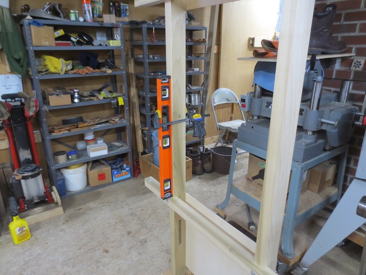
The front faces of the uprights should be plumb after the loom is attached to the wall.
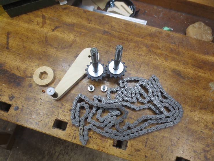
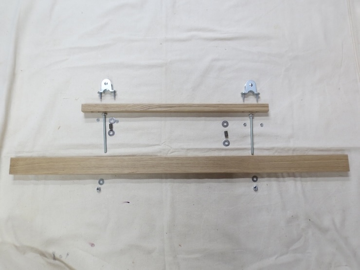
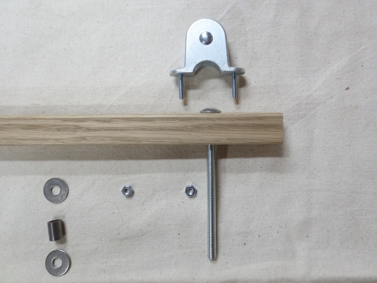
These parts will be added next.
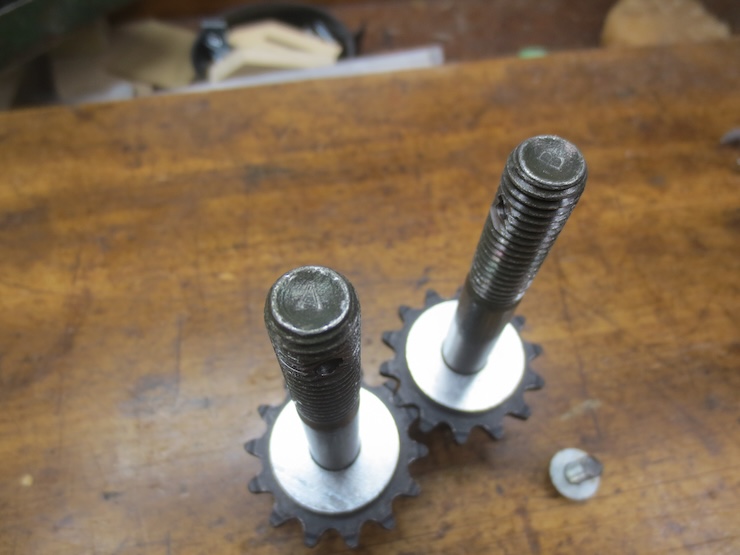
Note the letters stamped into the bolt ends.

The sprocket/bolt assembly marked “A” is being dropped into place over two washers. Repeat on the other side for sprocket/bolt “B”.
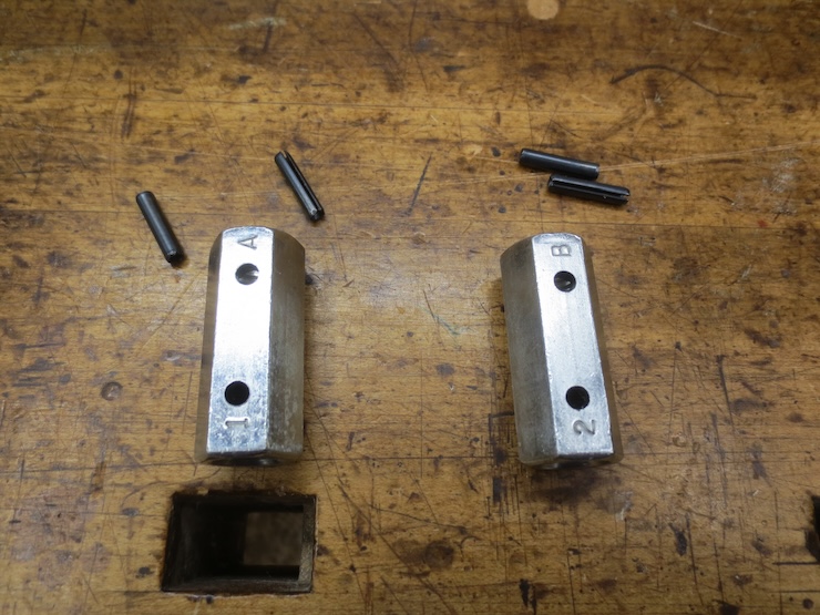
Remove the roll pins from the two connecting nuts. The end marked “A” will connect with sprocket bolt “A”. Same for “B” on other side.
Thread the connecting nut on until the holes line up and push in a roll pin. The pins are intentionally made a little loose. You may decide to tape them in place later if they tend to come out.
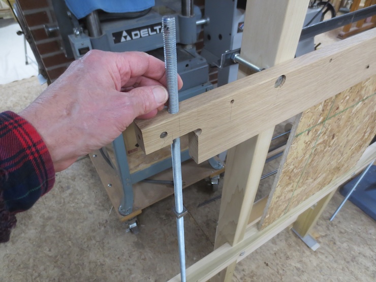
Find the lead screw that matches the number on the connecting nut.

Lower it down through the nylon bushing in the lower cross piece and leave it for now. Repeat on other side with lead screw “2”. The square nuts should be about halfway down with their flat sides facing up.
These parts will be added next.
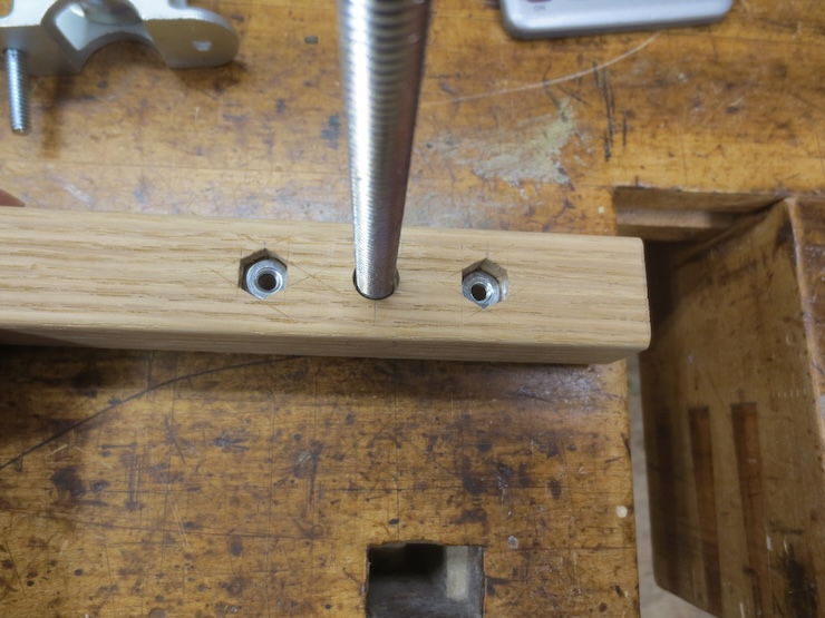
The nut on the left is tightened to fasten the carriage bolt firmly in place. For now the other parts are left loose.
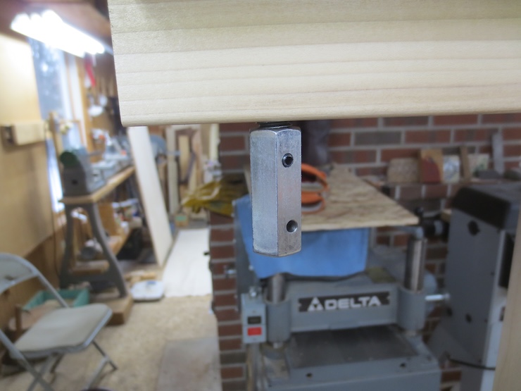
Clamp a scrap of wood to the front of the loom to provide a place for the ‘traveling beam’ to rest. The top edge should be level.
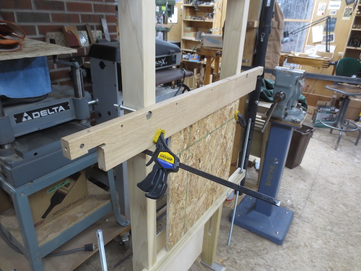
After removing the angle iron place the traveling beam on top of the scrap and clamp it so it won’t fall off.
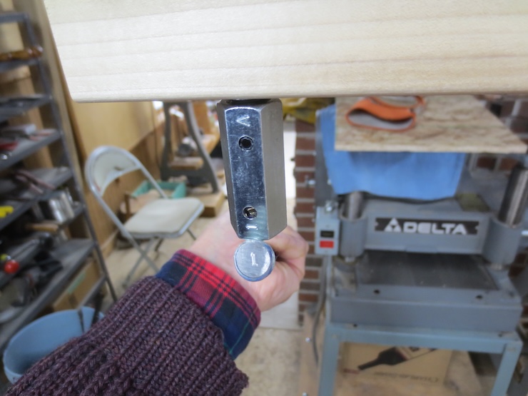
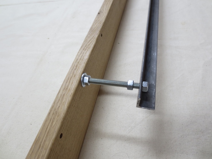
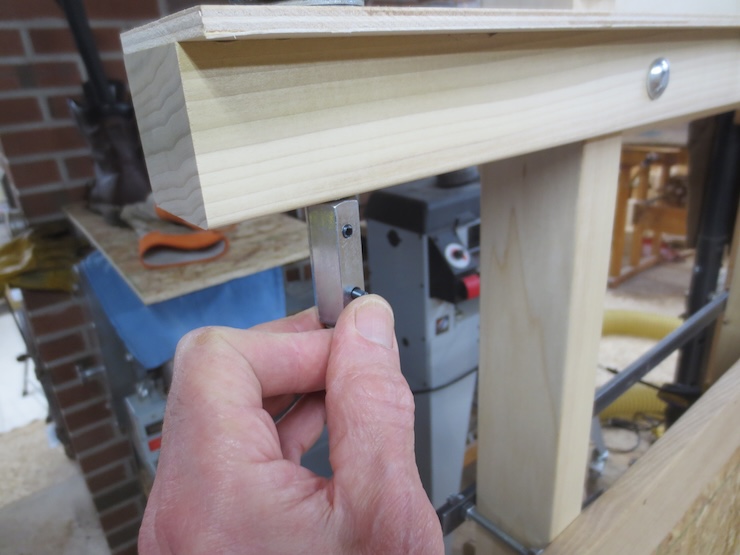
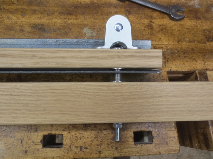
Fit the angle iron over the bolts and thread the nuts on loosely.
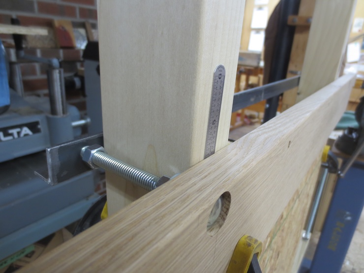
Remove the clamp and use the back nuts to hold a pair of shims in place. I used steel rules about .020″ (.5mm) thick. The idea is to leave a little space here so the beam may move easily but without sagging forward.

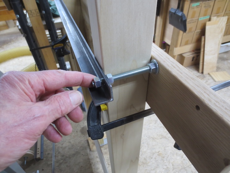
Tighten the back nuts evenly (finger-tight) and then tighten the middle nuts against the angle with a wrench before removing the shims.
Lift a lead screw up to connect it to the sprocket bolt. Rocking the beam a little may free up the lead screw as they tend to bind in the holes.
Insert a roll pin and repeat for the other side.
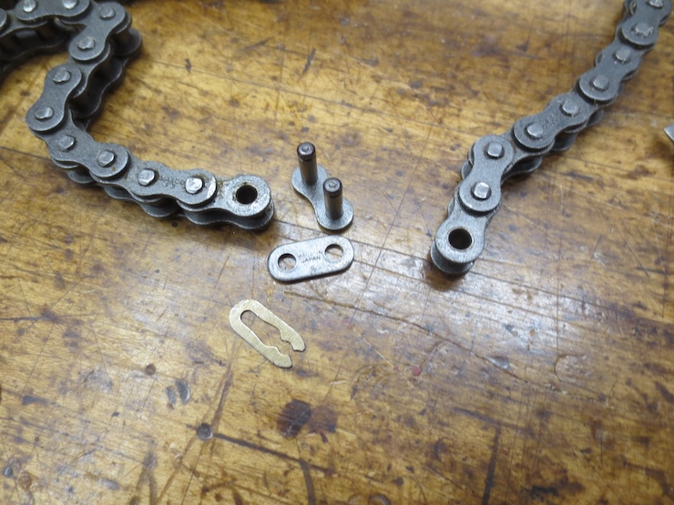
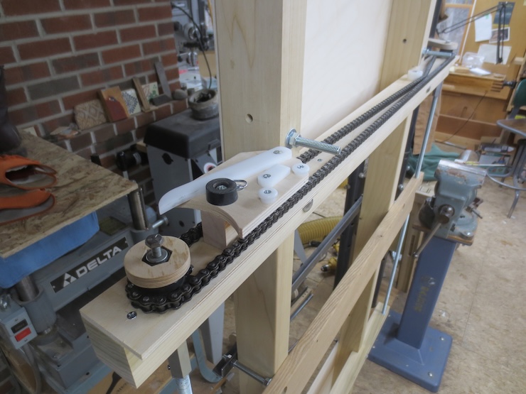
Fit the roller chain around the sprockets before fitting the connecting link.
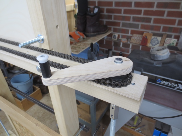
Add the crank.
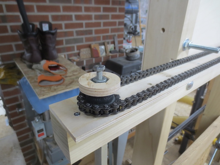
This spacer provides a surface for the indexing ‘counting’ discs to attach later.

This plastic cylinder tightens the chain up a bit. The chain should not be tight.
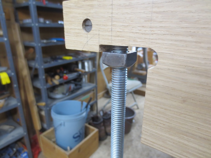
Spin the square nuts up by hand until each one just touches the bottom of the beam. Then lift each end of the beam just enough to turn the nuts another 1/4 turn. The nuts will now be trapped. Turn the crank clockwise to lift the beam. The scrap can be unclamped and removed.
This ratchet/pawl assembly is attached with two screws.
There parts will be added next. Note that the nylon bushings face inward and that the shaft is located above center.
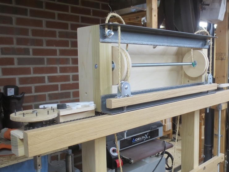
Insert the pulley shaft ends into the nylon bushings.
Place this assembly over the bolts. (Nuts and washers having been removed).
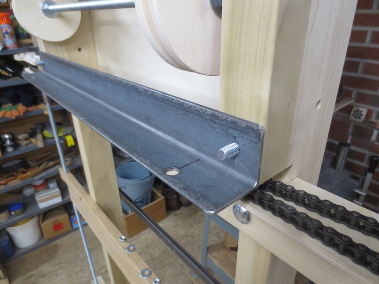
The bottom angle should look like this.
The top angle iron should look like this. The extra washers and nut will secure the ends of the lift rope later.
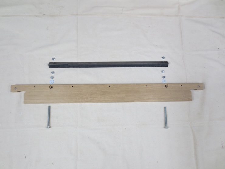
These parts will be added next.
The two carriage bolts must be inserted first before the steel pulley is fastened in place.
Place the small nuts in their pockets.
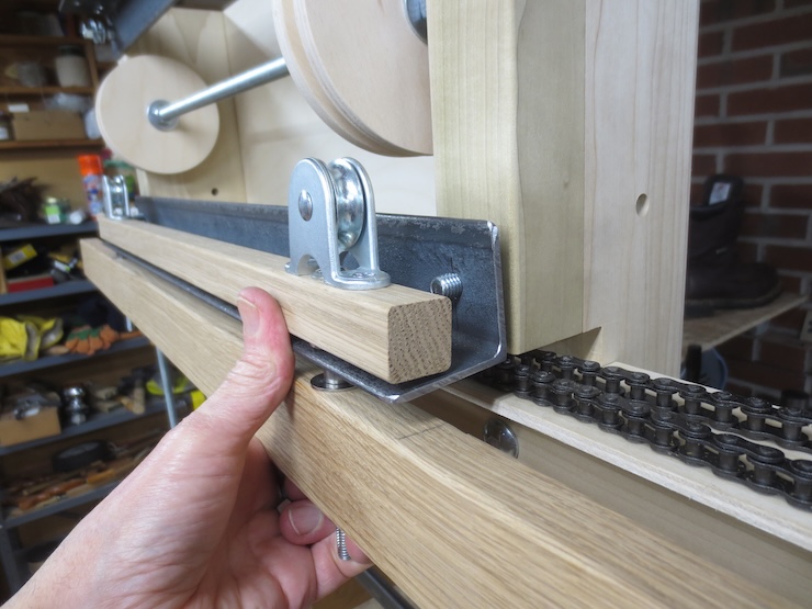
Small flat head screws (and the nuts) secure the pulleys to the beam. Then the parts are placed in the order shown above before tightening the nuts to tighten the entire assembly. (Stainless steel washer/bushing/stainless steel washer/lower wooden beam/plain flat washer/nut) The two special washers provide positive ‘stops’ for the up and down ‘lift’ movement while the 1/2″ long bushing slides smoothly in the hole drilled through the steel angle.
Lift the assembly over the bolt ends and secure with nuts.
These parts will be next.
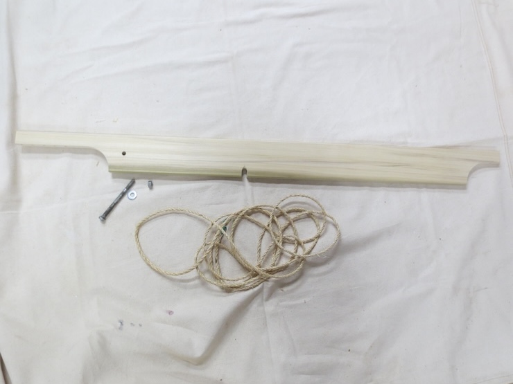
The treadle lift lever is secured with a single hex bolt.
Find the middle of the rope and locate it in the notch of the lift lever. Here one end of the rope is held with a clamp while the first (left hand) end is rigged. Next the right hand side can be rigged.
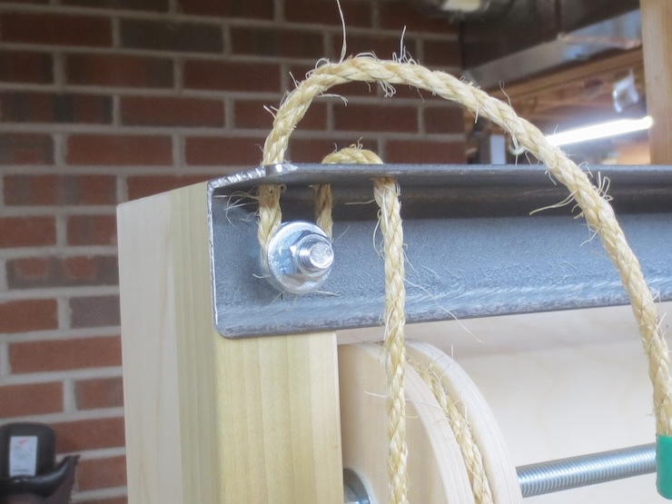
The rope passes up and over the wooden pulley before passing down and through the steel pulley. From there it rises straight up through the front hole drilled in the upper angle. To hold the rope in place the end is passed down through the next hole, around the bolt (between a pair of washers) and back up through the last hole. After the rope is tensioned correctly the nut is tightened to clamp the rope.
To be continued…
